Cirs Brachytherapy QA Phantom User manual
Brachytherapy QA Phantom
ZERDINE®Inside
A registered trademark of CIRS
USER GUIDE
U
L
T
R
A
S
O
U
N
D
Q
U
A
L
I
T
Y
A
S
S
U
R
A
N
C
E
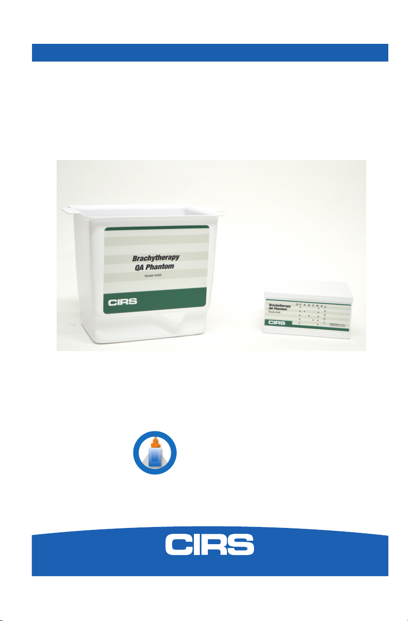
Brachytherapy QA
Phantom
Model 045B
900 Asbury Ave • Norfolk, Virginia 23513 • USA • Tel: 757-855-2765 • WWW.CIRSINC.COM

TABLE OF CONTENTS
1 OVERVIEW
1
2 INSTRUCTIONS FOR USE
4
HANDLING AND CARE
��������������������������������������������������������������� 4
GENERAL GUIDELINES FOR PERFORMING MEASUREMENTS
������������������������� 5
ESTABLISHING A BASELINE
��������������������������������������������������������� 6
3 TESTING PROCEDURES
6
UNIFORMITY TESTING
��������������������������������������������������������������� 7
DEPTH OF PENETRATION
������������������������������������������������������������ 7
VERTICAL AND HORIZONTAL DISTANCE MEASUREMENT
����������������������������� 8
ELECTRONIC GRID ACCURACY
������������������������������������������������������� 9
STEPPING MECHANISM ACCURACY
������������������������������������������������� 9
VOLUME MEASUREMENT ACCURACY
����������������������������������������������� 10
NEEDLE ALIGNMENT TESTING
������������������������������������������������������ 12
4 SPECIFICATIONS
13
5 ZERDINE®
14
6 WARRANTY
15
7 APPENDIX: QUALITY ASSURANCE RECORD FOR MODEL 045B
16

1
OVERVIEW
The Model 045B is sturdy, reliable
phantom for testing the imag-
ing performance of side-fire and
bi-plane probes used for trans-
rectal ultrasound imaging in prostate
brachytherapy seed implantation.
The Model 045B phantom offers a
complete solution for implement-
ing a brachytherapy QA program as
recommended by AAPM Task Group
128.1
The phantom is supplied with a water
tank for vertically coupling a trans-
ducer to the scanning membrane.
Brachytherapy needle grid QA can
be accomplished using the space
available inside the water tank as
specified by Goldstein et al.2 The tank
has two angled slots to allow the phantom to be positioned at a 30° angle which
simplifies use with floor-mounted TRUS systems. When testing table-mounted
TRUS systems, the phantom membrane can be oriented vertically. (See page 2
and 3 for images.)
The Model 045B has a series of monofilament targets that will appear as bright dots
or lines on the ultrasound image. These targets are made from monofilament nylon
wire with a diameter of 0.4 mm and a positional accuracy of ±0.2 mm. There are
also three volumetric targets. These targets are made from Zerdine that has a differ-
ent contrast relative to the background material.
CIRS is certified to ISO 13485:2016 standards. We have an in-house test facility to
measure acoustic properties of speed, attenuation and relative contrast. In addition,
two ultrasound systems are used to visually inspect each phantom. As a result,
every ultrasound phantom is subjected to rigorous testing both during manufacture
and upon completion. A Certificate of Compliance is issued with each phantom.
For further guidance on establishing a quality assurance program, you may want to
reference the accreditation programs established by the ACR and AIUM. You can
access this information at www.acr.org or www.aium.org. If additional information
is required, please call CIRS technical service at 1-800-617-1177.
1. Pfeiffer, Douglas, et al., AAPM Task Group 128: Quality assurance tests for prostate brachytherapy ultrasound systems.
Med. Phys., vol. 35 (12), pgs. 5471-5489, December 2008.
2. Goldstein, A., Yudelev, M., Sharma, R.K. and Arterbery, E. (2002), Design of Quality Assurance for Sonographic Prostate
Brachytherapy Needle Guides. Journal of Ultrasound in Medicine, 21: 947-954. doi:10.7863/jum.2002.21.9.947
Consistency Measure-
ments with the Model
045B
• Uniformity
• Depth of Penetration
• Vertical distance measurement
accuracy
• Horizontal distance measurement
accuracy
• Electronic Grid Accuracy
• Stepping Mechanism Accuracy
• Volume Measurement Accuracy
• Needle Alignment Testing

2
Phantom is placed vertically in water tank for testing. Tank needs to be filled with
water prior to use.

3
Phantom can be positioned at 30-degrees for compatibility with floor
mounted brachytherapy systems.

4
INSTRUCTIONS AND USE
HANDLING AND CARE
With proper care, the Model 045B will withstand years of normal use. Below are
some guidelines to follow.
The scanning surface is the most important item on the phantom to protect. It can
withstand normal scanning pressure but DO NOT press on the scanning surface
with your fingernails or any other sharp objects. If the scanning surface becomes
damaged, seal the phantom in an airtight container and IMMEDIATELY contact
RMA Request form to 757-857-0523.
The phantom may be cleaned with mild soap and water ONLY. Avoid solvent-
based, alcohol-based, or abrasive cleaning agents.
For longest life, the phantom should be cleaned after each use and stored at room
temperature in the provided zip-lock bag. The primary concern is gel desiccation
due to loss of water vapor through the membrane. In addition, the thermal stresses
associated with a freeze/thaw cycle may cause the gel to crack or damage the
housing integrity, while extreme heat may accelerate water vapor transmission
through the membrane. To minimize desiccation, always store the phantom in a
sealed zip-lock bag or an equivalent air-tight, sealed container.
Inspect your phantom regularly for signs of damage and weight loss. If any notice-
able changes to the phantom are detected, return the phantom IMMEDIATELY for
repair or replacement.
At least once a year, weigh your phantom and compare to original
weight noted on certificate of compliance. If the phantom has lost
or gained more than 1% of its original weight and you notice a dif-
ference in vertical distance measurements, or if the scan surface
appears depressed, call CIRS at (800) 617-1177.
This product contains Zerdine, a non-flowing water-based, poly-
acrylamide material which is fully sealed within the phantom housing.
Zerdine contains trace amounts of the residual monomer acrylamide
CAS#79-06-1. There are no known hazards when the phantom
is used and stored as intended. Zerdine is fully cured and will not
leak from the housing. Damage to the integrity of the housing may
expose the user to trace amounts of acrylamide monomer. The
amount is not sufficient to pose an acute health risk, but it is still
advised to wear protective gloves if handling exposed Zerdine gel
due to the potential long-term hazards of the monomer. It is also
advisable to wash hands and all surfaces with soap and water after
handling exposed Zerdine gel.

5
HANDLING AND CARE (CONTINUED)
Regulations regarding disposal of materials with trace acrylamide
monomer vary by locality. Contact your local authority for instruc-
tions. If assistance is desired in the proper disposal of this product,
including accessories and components, after its useful life, please
return to CIRS.
GENERAL GUIDELINES FOR PERFORMING MEASUREMENTS
It is recommended that all measurements be performed at the most frequently used
imaging arrangements. The importance of these tests is to make sure that system
performance remains constant over an extended period of time. Measurements
may also be used to compare the performance of various setups of the same ma-
chine or to compare different machines in a quantitative manner.
The following are general steps for imaging all targets:
• Some wires will appear as short lines rather than dots. When using the
electronic calipers, always take measurements from a point on one echo
to the same point on the next (i.e., center to center). Otherwise, errors may
be introduced.
• When assessing vertical distance measurements, DO NOT press on the
scanning surface. Pressure on the scanning surface causes the wires
to become temporarily displaced, making vertical distance measure-
ments inaccurate.
• When assessing horizontal distance accuracy, ensure that the scan plane is
perpendicular to the horizontal target group. Rotation of the probe will result
in inaccurate distances.
• Always be sure the phantom is scanned while at room temperature. A
phantom just received may be colder or hotter than room temperature de-
pending on where it was stored during shipping. Temperature affects the
speed of sound and, ultimately, the perceived measurements. The phantom
should be stored at room temperature for at least 24 hours before use to
ensure its core temperature is correct.
• The most accurate measurements will be made with the phantom 22˚C ±
1˚C (70˚F–73˚F).

6
ESTABLISHING A BASELINE
Before performing routine quality assurance measurements, establish:
1. System settings for each measurement:
System setup can have a dramatic impact on the results obtained from quality
assurance measurements. You must establish and record what system
settings should be used for each of the quality assurance tests. These
same settings should be used each time the test is performed. If not, then the
conclusions drawn may not be valid. CIRS recommends that you use the most
commonly used settings for the type of probe tested- i.e. the brachytherapy
preset values which are called a "normal" technique in the sections that
follow.
2. Baseline measurements:
The first set of measurements taken will be the baseline measurements for the
combination of system settings and phantom. Record the system settings and
phantom serial number used to acquire each measurement along with
your measurement results. On subsequent scans, refer to the baseline results
to determine if the ultrasound system has drifted to an unacceptable level. It is
each facility's responsibility to establish the magnitude of drift allowed
before corrective action is warranted.
3. Allowable deviation from baseline measurements:
The difference between the original baseline measurements and subsequent
measurement should be calculated and recorded. At some point the difference
will be large enough that some action is required (call service, replace system,
etc.). Each facility needs to determine the action level for each test. You should
refer to the user’s manual of your ultrasound scanner and note the stated
accuracies of the system’s general imaging measurements. These stated ac-
curacies may greatly influence the conclusion made when evaluating the ultra-
sound system. For example, if the measurement accuracy for your system
is 10% for distances up to 2 cm, the scanner may detect 2.0 cm as being any
where from 1.8 cm to 2.2 cm and still be functioning properly. The user is
responsible for establishing action levels.
4. Frequency of system assessment:
How often each system is evaluated is also up to each facility to determine.
CIRS recommends at least annually.
Reference the accreditation programs established by the ACR and AIUM at
www.acr.org or www.aium.org for further guidance on establishing a QA program.
TEST PROCEDURES
The following sections outline procedures for performing routine quality control tests
with the imaging targets contained within the Model 045B. The water tank should
be filled with water and phantom placed inside the tank when performing test proc-
dures. See the following references on page 7 for further test procedure details:

7
Pfeiffer, Douglas, et al., AAPM Task Group 128: Quality assurance tests for prostate brachytherapy ultrasound systems. Med.
Phys., vol. 35 (12), pgs. 5471-5489, December 2008.
Goldstein, A., Yudelev, M., Sharma, R.K. and Arterbery, E. (2002), Design of Quality Assurance for Sonographic Prostate
Brachytherapy Needle Guides. Journal of Ultrasound in Medicine, 21: 947-954. doi:10.7863/jum.2002.21.9.947
UNIFORMITY
Uniformity is defined as the ability of the machine to display echoes of the same
magnitude and depth with equal brightness on the display. This is a good test to
ensure all crystals within the transducer are functioning. Uniformity testing is per-
formed as follows:
1. Position the transducer on the scanning surface in a region with a
minimum number of targets.
2. Adjust the instrument settings (gain, TGC, output, etc.) as for a “normal”
technique. Record these settings for use on subsequent testing.
3. Align the probe so that the targets are maximized.
4. Freeze the image and obtain a hard copy.
5. Observe the general appearance of the phantom. Note if all regions at the
same depth are displayed with the same intensity across the width of the
image.
6. Record your observations.
DEPTH OF PENETRATION TESTING
Depth of penetration, also called maximum depth of visualization or sensitivity, is the
greatest distance in a phantom for which echo signals caused by scattering in the
background material can be detected on the display. The depth of penetration is
determined by the frequency of the transducer, the attenuation of the medium being
imaged and the system settings. It is measured with the aid of the “N” group wire
targets, as follows:
1. Position the transducer above the “N” Group and perpendicular to the wires.
(The wires should appear as dots, not lines).
2. Adjust the instrument settings (gain, TGC, output, etc.) as for a “normal”
technique. Record these settings for use on subsequent testing.
3. Align the probe so that all the vertical targets are displayed at their maximum
intensity level.
4. While actively scanning, look to see where the scatterers within the background
material disappear. Be careful not to confuse electronic noise with the back
ground scatterers. Electronic noise will move; scatterers will remain stationary.
5. Freeze the image.
6. With electronic calipers measure the distance between the scanning surface
and the last identifiable echo due to scattering. Note: The wires may be visible
even though the scatterers are not. Remember to measure the distance to the
scatterers not the last visible wire.

8
7. Record this distance on a record sheet and compare with baseline depth.
VERTICAL AND HORIZONTAL DISTANCE ACCURACY- USING ELECTRONIC CALIPERS
If the displayed grid does not line up with the N-shaped target group or you want
a more precise measure of distance accuracy, electronic calipers may be used.
Vertical distance is defined as the distance along the axis of the beam. Horizontal
distance is defined as the distance along the length of the transducer. Distances
are used to measure areas, volumes, depths, and sizes of objects. The vertical ar-
ray of targets at column B and F on the phantom diagram allow one to assess the
accuracy of the vertical measurements while the horizontal array of targets at row 1
through 5 assess horizontal measurement accuracy. For bi-plane probes, the cross-
ing wires in the z-axis can also be used for horizontal measurements and provide
spacing from 0.5 cm to 5.0 cm.
1. Adjust the instrument setting (gain, TGC, output, etc.) as for a “normal” tech-
nique. Record these settings for use on subsequent testing.
2. Align the probe so the N-shaped target group is maximized.
3. Freeze the image.
4. Using electronic calipers, measure the distances between two wires at various
depths or align the echoes to the ultrasound system display markers for com-
parison.
5. Record measurements.
6. Compare measured values with baseline distances.
7. Repeat steps using horizontal targets in N-shaped group.
VERTICAL AND HORIZONTAL DISTANCE ACCURACY
Vertical distance is defined as the distance along the axis of the beam while
horizontal distance is defined as the distance along the length of the transducer.
Distances are used to measure areas, volumes, depths, and sizes of objects. Using
the “N” target group, the vertical array of targets at column B and F on the phan-
tom diagram allow one to assess the accuracy of the vertical measurements while
the horizontal array of targets at row 1 through 5 assess horizontal measurement
accuracy. For bi-plane probes, the crossing wires in the z-axis can also be used for
horizontal measurements and provide spacing from 0.5 cm to 5.0 cm.
For the most precise assessment of vertical and horizontal distance measurement
accuracy, used the electronic calipers as follows:
1. Adjust the instrument setting (gain, TGC, output, etc.) as for a “normal” tech-
nique. Record these settings for use on subsequent testing.
2. Align the probe so the N-shaped target group is maximized.
3. Freeze the image.

9
VERTICAL AND HORIZONTAL DISTANCE ACCURACY (CONTINUED)
4. Using electronic calipers, measure the distances between two wires at various
depths or align the echoes to the ultrasound system display markers for com-
parison.
5. Record measurements.
6. Compare measured values with baseline distances.
7. Repeat steps using horizontal targets in N-shaped group.
ELECTRONIC GRID ACCURACY
One important aspect for any brachytherapy procedure is accurate placement of
seeds within the prostate. An integral part of seed placement and treatment plan-
ning is the accuracy of the distances measured. By aligning this grid to the “N”
target of the phantom, users can perform a quick check vertical and horizontal
distance accuracy as follows:
1. Adjust the instrument setting (gain, TGC, output, etc.) as for a “normal” tech-
nique. Record these settings for use on subsequent testing.
2. Align the probe so the N-shaped target group is maximized.
3. Secure your transducer and position the stepping/stabilization unit accordingly.
For ease of alignment you may want to place the front surface of the phantom
in contact with the needle template. Adjust the probe/phantom position until
the targets are aligned with the displayed grid. It may be easiest to align the
center target with the center-displayed target and then try to align the rest of
the grid.
4. Proper alignment is achieved when the displayed grid is superimposed on wire
target echoes. The wires may appear larger or smaller than the displayed grid
dots. If the targets appear larger, try to align the centers of the targets with the
displayed grid dots. Depending on the manufacturer of your brachytherapy
system and ultrasound machine, Row 1 on the phantom may or may not repre-
sent Row 1 on the displayed grid. If you have difficulty aligning the targets
with the displayed grid, you can assess horizontal and vertical distance accu-
racy by using the electronic calipers.
5. Record results.
STEPPING MECHANISM ACCURACY
Just as vertical and horizontal distance measurements are important for accurate
seed placement in the x-axis and y-axis, the condition of the stepping mechanism is
critical to accurate seed placement in the z-axis. Perpendicular to the N-shaped tar-
get group are five wires all at the same distance from the transducer, but separated
by 0.5 cm and 1.0 cm in the z-axis.

10
STEPPING MECHANISM ACCURACY (CONTINUED)
1. Adjust the instrument setting (gain, TGC, output, etc.) as for a “normal” tech-
nique. Record these settings for use on subsequent testing.
2. Align the probe so targets are maximized.
3. Insert the transducer towards the back of the scanning cavity and align the
beam with the crossing wire number 6 as indicated on the side of the phantom.
This target will appear as a short line in row 4 above the transducer. Once this
target is visualized, secure the stepping mechanism in place.
4. The next crossing wire (#5) is exactly 1.0 cm from wire #6 in the z-axis. Using
the stepping mechanism, retract the transducer by 1 cm (in most cases this is
two “clicks” on the stepping mechanism). Wire #5 will now be visible if the
mechanism is working. If no wire is visible, the stepper has either retracted the
transducer too much or too little. Manual manipulation of the transducer for-
ward and backward to the target may give you some approximation as to the
degree of error. Note: The accuracy of this assessment is dependent on the
width of the ultrasound beam.
5. Record results.
6. Repeat for various retraction distances as specified in your QA plan.
VOLUME MEASUREMENT ACCURACY
Dose mapping is heavily dependent on accurate assessment of prostate volume.
The Model 045B contains three different calibrated test objects specifically de-
signed to assess volume measurement accuracy. The volume of each test object is
physically measured with a tolerance of ± 0.5cc using Archimedes Principle before
insertion within the phantom. The volumes are recorded on the accompanying
certi-fication sheet. Perimeters which are estimated from the measured volume with
the equations listed below, are also provided. Perimeters stated in the certifications
are only intended to be used nominally. The small and medium volumes are
spherical, but the large volume is egg shaped as seen in figures 1 and 2.
Figure 1 Sphere volumes and perimeters (see certification sheet for actual values in your phantom)
END VIEW
SMALL SPHERE LAYOUT
R9.55mm
END VIEW
MEDIUM SPHERE LAYOUT
R12.7mm
=
4
3!≈3.6
=
4
3!≈8.6
=
2
3!+≈20
=
4
3!≈3.6
=
4
3!≈8.6
=
2
3!+≈20

11
Figure 2 Egg volume and perimeter (see certification sheet for measured values in your phantom)
LARGE EGG LAYOUT
a=14.7mm
b=29.5mmc=14.7mm
=
4
3!≈3.6
=
4
3!≈8.6
=
2
3!+≈20
Volume measurements are performed as follows:
1. Adjust the instrument setting (gain, TGC, output, etc.) as for a “normal” tech-
nique. Record these settings for use on subsequent testing.
2. Align the probe so targets are maximized.
3. Retract the probe as far as possible. If the probe is still within the phantom,
move the phantom away from the needle template until only the tip of the trans-
ducer is inside the cavity.
4. Rotate the probe 60 degrees clockwise or counterclockwise depending on what
size mass you wish to visualize.
5. Step the transducer forward until the mass is in view.
6. The volume of each test object should be computed using the methods/soft-
ware provided with the ultrasound system or as performed on a patient.
7. Record measurements.
8. Repeat steps for each volume within phantom.
VOLUME MEASUREMENT ACCURACY (CONTINUED)

12
NEEDLE ALIGNMENT TEST
Needle alignment testing of the brachytherapy system is important to ensure
potential accuracy in guiding radioactive seeds respective of the overlay grid on the
sonographic image.
1. Fill the water tank with water. Remove the phantom from the water tank or
position the transrectal probe into an area that only images the water bath.
2. The transrectal probe needs to be arranged vertically so that needles are held
parallel to the probe’s long axis.
3. Adjust the system settings as for a “normal” technique. Record these settings
to use on subsequent testing.
4. Place brachytherapy needles through the brachytherapy template grid. The
needles should pass into the water bath.
5. Measurements are performed to assess the displacement between echoes
of the needles and the on-screen grid. Use the caliper tools on the imaging
system to measure the difference between the template position indicated on
the sonographic image and the needle “flash” or echo.
6. Record measurements. Record template grid positions of needles to use on
subsequent testing.
7. Compare measured values with baseline or clinically acceptable deviations.

13
Brachytherapy
QA Phantom Model 045A
TOP
FRONT
LEFT RIGHT
20 cc
4 cc
9 cc
20 cc
9 cc
4 cc
0.5 cm
1 cm
0.5 cm
1 cm
1 cm
Brachytherapy
QA Phantom Model 045A
TOP FRONT
LEFT
RIGHT
20 cc
4 cc
9 cc
20 cc
9 cc
4 cc
0.5 cm
1 cm
0.5 cm
1 cm
1 cm
Brachytherapy
QA Phantom Model 045B
TOP FRONT
LEFT RIGHT
20 cc
4 cc
9 cc
20 cc
9 cc
4 cc
0.5 cm
1 cm
0.5 cm
1 cm
1 cm
Brachytherapy
QA Phantom Model 045A
TOP FRONT
LEFT
RIGHT
20 cc
4 cc
9 cc
20 cc
9 cc
4 cc
0.5 cm
1 cm
0.5 cm
1 cm
1 cm
Front view shows the N wire target group while the side views show the Cross Axis
wire targets.
Volumes are rounded to the nearest cubic centimeter. Please refer to phantom certi-
fication for measured volume.
PHANTOM HOUSING
Material 1/4” White PVC
Outer Dimensions 14 x 11 x 7.5 cm
SCANNING SURFACE
Material Saran-based laminate
WATER TANK
Material 3/16” White ABS
BACKGROUND MATERIAL
Material Zerdine
Speed of Sound 1540 m/s
Other Compatible with harmonic imaging
WIRE TARGETS
Material Nylon monofilament
Diameter 0.10 mm
TARGET LAYOUT
SPECIFICATIONS
Scan surface
Scan surface Scan surface

14
“N” GROUP
Number of targets 13
Depth range 2.0 cm to 6.0 cm
Vertical distance between targets 10.0 mm
Horizontal distance between targets 10.0 mm
CROSS-AXIS GROUP
Number of targets 5
Depth Row 3
Horizontal distance between targets 5.0 mm, 10.0 mm
CALIBRATED VOLUMES
Material Zerdine
Speed of Sound 1540 m/s
Attenuation Coefficient 0.5 dB/cm-MHz
Contrast ~+9 dB
Nominal Volumes 4 cc (S), 9 cc (M), 20 cc (L)
ACCESSORIES
Certificate of Compliance, Water Tank
Model 045B User Guide & Technical Information, QA Worksheet
NOTES
All dimensions without tolerances are nominal
All measurements made at 22˚C ± 1˚C
ZERDINE®
The Model 045B is constructed from a patented, solid elastic material developed
at CIRS called Zerdine. Zerdine, unlike other phantom materials on the market, is
not affected by changes in temperature. It can be subjected to boiling or freezing
conditions without sustaining significant damage. Zerdine is also more elastic than
other materials and allows more pressure to be applied to the scanning surface
without subsequent damage to the material. At normal room temperatures, Zerdine
will accurately simulate the ultrasound characteristics found in human liver tissue.
Specific proprietary fabrication procedures enable close control over the homoge-
neity of Zerdine and the reliability of its acoustic characteristics from batch to batch.
The speed of sound in Zerdine can be adjusted between 1430 and 1650 meters
per second. The acoustic attenuation can be adjusted between 0.05 dB/cm-MHz
and 1.50 dB/cm-MHz. The relation between the acoustic attenuation, A, and the
acoustic frequency, F, is of the form A = AoFnwith values of the power coefficient,
n, in the range of 0.8 to 1.10, indicating the proportional increase of the acoustic
attenuation with frequency. Backscatter characteristics can be adjusted through
the addition of predetermined amounts of calibrated scatter material. Zerdine can
be molded into very intricate shapes, and the material can be cured in layers allow-
ing the production of “multi-tissue” phantoms. Zerdine, like most other phantom
materials, will desiccate if unprotected; thus, all phantoms must be stored properly.
If stored in the case provided, your phantom should last many years.

15
WARRANTY
All standard CIRS products and accessories are warranted by CIRS against defects
in material and workmanship for a period as specified below. During the warranty
period, the manufacturer will repair or, at its option, replace, at no charge, a product
containing such defect provided it is returned, transportation prepaid, to the manu-
facturer. Products repaired in warranty will be returned transportation prepaid.
There are no warranties, expressed or implied, including without limitation any im-
plied warranty of merchantability or fitness, which extend beyond the description on
the face hereof. This expressed warranty excludes coverage of, and does not pro-
vide relief for, incidental or consequential damages of any kind or nature, including
but not limited to loss of use, loss of sales or inconvenience. The exclusive remedy
of the purchaser is limited to repair, recalibration, or replacement of the product at
manufacturer’s option.
This warranty does not apply if the product, as determined by the manufacturer,
is defective because of normal wear, accident, misuse, or modification.
NON-WARRANTY SERVICE
If repairs or replacement not covered by this warranty are required, a repair estimate
will be submitted for approval before proceeding with said repair or replacement.
RETURNS
If you are not satisfied with your purchase for any reason, please contact Customer
Service or your local distributor prior to returning the product. Visit https://www.
cirsinc.com/distributors/ to find your local distributor. Call 800-617-1177, email
attempt to remedy the issue via phone or email as soon as possible. If unable to
correct the problem, a return material authorization (RMA) number will be issued.
Non-standard or “customized” products may not be returned for refund or ex-
change unless such product is deemed by CIRS not to comply with documented
order specifications. You must return the product to CIRS within 30 calendar days
of the issuance of the RMA. All returns should be packed in the original cases and
or packaging and must include any accessories, manuals and documentation
that shipped with the product. The RMA number must be clearly indicated on the
outside of each returned package. CIRS recommends that you use a carrier that
offers shipment tracking for all returns and insure the full value of your package so
that you are completely protected if the shipment is lost or damaged in transit. If
you choose not to use a carrier that offers tracking or insure the product, you will be
responsible for any loss or damage to the product during shipping. CIRS will not be
responsible for lost or damaged return shipments. Return freight and insurance is to
be pre-paid.
WITH RMA NUMBER, ITEMS MAY BE RETURNED TO:
CIRS
Receiving
900 Asbury Ave,
Norfolk, Virginia, 23513 USA
PRODUCT WARRANTY PERIOD
Model 045B - Brachytherapy QA
Phantom 48 Months

16
APPENDIX 1: QUALITY ASSURANCE RECORD FOR MODEL 045B
MODEL 045B
BRACHYTHERAPY QA PHANTOM
QUALITY ASSURANCE RECORD
Parameter Actual
Value
Baseline
Value
Measured
Value Drift Corrective
Action Comments
Uniformity
Depth of
Penetration
Small Volume
Vertical and
Horizontal
Distance
Electronic
Grid
Accuracy
Stepping
Mechanism
Volume
Measurement
Accuracy
Needle
Alignment
Test
Miscellaneous Checks
Check for damage on the following items: (space provided for comments)
· Transducer (cord, housing, & face)_______________________________________
· System (cord, knobs, wheels)____________________________________________
Clean the following items: (Space provided for comments)
· Transducer__________________________________________________________
· Monitor_____________________________________________________________
· Keyboard & Knobs____________________________________________________
· Air lters____________________________________________________________
· Misc._______________________________________________________________
Directions for Use:
1. Use this form to plan and record your quality assurance program.
2. Use one form for each transducer.
3. For Baseline measurements ll out system settings and baseline measurements.
4. Use comments section to indicate changes in system settings for a particular measurement and other
observations.
5. Use a photocopy of baseline form for subsequent test results (one for each test date).
MODEL 045A
BRACHYTHERAPY QA PHANTOM
QUALITY ASSURANCE RECORD
Name:_____________________ Date:________________________ Phantom Info:
________________
Baseline System I.D.___________________
____________________________
Date:______________________ Transducer I.D.________________
____________________________
System Settings
Overall Gain:________________ Post Processing:________________ Depth of
Field:________________
TGC Settings:_______________ Dynamic Range:________________
Power:______________________
Focal Points:________________ Preprocessing:_________________
Other:_______________________
Parameter
Actual
Value
Baseline
Value
Measured
Value
Drift
Corrective
Action
Comments
Vertical
Distance
Horizontal
Distance
Small
Volume
Medium
Volume
Large
Volume
Stepping
Mechanism
Uniformity
Other

17

©
2020 Computerized Imaging Reference Systems, Inc. All rights
reserved.
Specifications subject to change without notice.
Publication: 045B UG 102620
Computerized Imaging Reference Systems, Inc. has
been certified by UL DQS Inc. to (ISO) 13485:2016.
Certificate Registration No.10000905-MP2016.
COMPUTERIZED IMAGING
REFERENCE SYSTEMS, INC.
900 Asbury Ave
Norfolk, Virginia 23513 USA
Toll Free: 800.617.1177
Tel: 757.855.2765
Fax: 757.857.0523
Email [email protected]
www.cirsinc.com
Technical Assistance
1.800.617.1177
This manual suits for next models
1
Table of contents
Other Cirs Medical Equipment manuals


