Sonatest Masterscan D-70 User manual

Document Number: Issue 0 September 2014
Masterscan D-70
User’s Guide
17/09/2014

Masterscan D-70 user’s manual
1
How to contact Sonatest?
Visit our website: www.sonatest.com or contact our offices.
Sonatest Limited (International)
Dickens Road
Milton Keynes
MK12 5QQ
England
+44 (0)1908 316345
+44 (0)1908 321323
Sonatest Inc
. (America)
12775 Cogburn
San Antonio, Texas
78249
USA
+1 (210) 697 0335
+1 (210) 697 0767

Masterscan D-70 user’s manual
2
Disclaimers and Notices
The following information must be read and understood by users of the Sonatest Masterscan D-70
ultrasonic flaw detector and thickness gauge. Failure to follow these instructions can lead to serious
errors in test results or damage to the flaw detector. Decisions based on erroneous results can lead
to property damage, personal injury or death. Anyone using this instrument should be fully qualified
by their organization in the theory and practice of ultrasonic testing, or under the direct supervision
of such a person.
General Warnings
Proper use of the ultrasonic test equipment requires four essential elements:
Knowledge of the specific tests or inspections and applicable test equipment.
Selection of the correct test equipment based on knowledge of the application.
Competent training of the instrument operator.
This user’s guide provides instruction in the basic operation of the Masterscan D-70 flaw
detector. In addition to the methods included, many other factors can affect the use of
this flaw detector. Specific information regarding these factors are beyond the scope of
this manual. The user should refer to appropriate textbooks on the subject of ultrasonic
testing and thickness gauging for more detailed information.
Specific Warnings
The Masterscan D-70 contains a high-energy, precision pulser allowing optimum test
results to be obtained by matching the pulse width to the probe characteristics. This
circuitry may be damaged by voltage spikes. It is recommended that the instrument be
switched off, or the pulser stopped (by pressing the
[Freeze/Peak]
key) before changing
probes.
Operator Training
Operators must receive adequate training before using this ultrasonic flaw detector.
Operators must be trained in general ultrasonic testing procedures, and in the set-up and
performance required by each specific test or inspection. Operators must understand: Sound
wave propagation theory.
Must understand the effects of the velocity of sound in the test material.
Must know the behaviour of the sound wave at the interface of two different materials.
Must have an understanding of Sound wave spread and mode conversion.
More specific information about operator training, qualification, certification and test specifications
can be obtained from technical societies, industry groups and government agencies.

Masterscan D-70 user’s manual
3
Testing Limitations
In ultrasonic testing, information is obtained only from within the confines of the sound beam as it
propagates into the test material. Operators must exercise great caution when making inferences
about the nature of the test material outside the limits of the sound beam. The condition of
materials can vary significantly and the results can be erratic if operators don’t exercise good
judgment.
Critical Operating Factors
The following procedures must be observed by all users of the Masterscan D-70 in order to obtain
proper, accurate and consistent results.
Calibration of the Sound Velocity
An ultrasonic flaw detector operates on the principle of measuring the time of flight of a burst of high
frequency sound through the test piece, as well as evaluating the amplitude of reflected or
transmitted echoes. The sound velocity of the test piece multiplies this time in order to obtain an
accurate distance or thickness reading. Since the actual sound velocity in materials can vary from the
published values, the best result is obtained when the instrument is calibrated on a reference block
made from the same material as the test piece. This block should be flat, smooth and as thick as the
maximum thickness expected of the test piece.
Users should also be aware that the sound velocity might not be constant throughout the test piece
due to effects such as heat-treating. This must be taken into consideration when evaluating the
results of ultrasonic thickness testing. The calibration should always be checked after testing to
minimize errors.
Transducer (Probe) Zero Procedure
The transducer calibration procedures must be performed as described in this manual. The
calibration block must be clean, in good condition and free of noticeable wear. Failure to perform
the transducer zero and calibration procedure will cause inaccurate thickness readings.
Flaw Detection Calibration
When performing a flaw detection test, it is important to note that the amplitude of indications is
not only related to the size of the discontinuity; the depth of a discontinuity below the test piece
surface will also have an effect on the amplitude due to characteristics of the sound beam spread
and near field zone of the transducer. In addition, the characteristics of the discontinuity such as
orientation and classification can alter the expected amplitude response. For these reasons,
calibration should be performed on test blocks made of the same material as the test piece with
artificial discontinuities within the range of size and depth in the material to be detected. The user is
again cautioned to refer to reference books which are beyond the scope of this manual.

Masterscan D-70 user’s manual
4
Effects of Temperature on Calibration
The sound velocity in test pieces and the transducer wear face changes with temperature variations.
All calibrations should be performed on site with test blocks at or near the same temperature as that
expected on the test piece, to minimize errors.
Transducer Condition
The transducer used for testing must be in a good condition, without noticeable wear of the front
surface. The specified range of the transducer must encompass the complete range of the thickness
to be tested and/or the types of discontinuities to be investigated. The temperature of the material
to be tested must be within the transducer’s specified temperature range.
Use of Couplant
Operators must be familiar with the use of ultrasonic couplant. Testing skills must be developed so
that couplant is used and applied in a consistent manner to eliminate variations in couplant thickness
which can cause errors and inaccurate readings. Calibration and actual testing should be performed
under similar coupling conditions, using a minimum amount of couplant and applying consistent
pressure to the transducer
Disclaimer of Liability
All statements, technical information and recommendations contained in this manual or any other
information supplied by Sonatest Limited in connection with the use, features and qualifications of
the Masterscan D-70 are based on tests believed to be reliable, but the accuracy or completeness
thereof is not guaranteed. Before using the product you should determine its suitability for your
intended use based on your knowledge of ultrasonic testing and the characteristics of materials. You
bear all risk in connection with the use of the product. You are reminded that all warranties as to
merchantability and fitness for purpose are excluded from the contract under which the product and
this manual have been supplied to you. The Seller’s only obligation in this respect is to replace such
quantity of the product proved to be defective.
Neither the seller nor the manufacturer shall be liable either in contract or in tort for any direct or
indirect loss or damage (whether for loss of profit or otherwise), costs, expenses or other claims for
consequential or indirect compensation whatsoever (and whether caused by the negligence of the
company, its employees or agents or otherwise).
Your product package may include optional documentation, such as warranty flyers, that may have
been added by your dealer. These documents are not part of the standard package.

Masterscan D-70 user’s manual
5
Copyright
Copyright © 2006 –2014 Sonatest Limited. All rights Reserved
All rights reserved. No part of this publication may be reproduced, stored in a retrieval system or
transmitted in any form or by any means, electronic, mechanical, photocopying, recording or
otherwise, without the prior written permission of Sonatest Limited.
Sonatest limited or its filial provides this manual “AS IS” without warranty of any kind, either express
or implied. Included but not limited to the implied warranties or conditions of merchantability or
fitness for a particular purpose. In NO events shall Sonatest Limited, its filial, its directors, officers,
employers or agents be liable for indirect, special, incidental, or consequential damage, even if
Sonatest limited or its filial has been advised of the possibility of such damages arising from any
defect or error in this manual or product.
Specifications and information contained in this manual are furnished for informational use only, and
are subject to change at any time without notice, and should not be construed as a commitment by
Sonatest limited or its filial.

Masterscan D-70 user’s manual
6
Electromagnetic Compatibility
This product has been design to the following European Directives:
-Directive 2002/95/EC on the Restriction of the Use of certain Hazardous Substances in Electrical and
Electronic Equipment (RoHS).
-Directive 2002/96/EC on Waste Electrical and Electronic Equipment (WEEE)
-Low Voltage Directive (LVD) 73/23/EEC
-CE Marking Directive 93/68/EEC
-EMC Directive 89/336/EEC. However, in order to ensure the equipment meets the requirements, the
following should be read:
This is a “CLASS A” product. In a domestic environment, this product may cause radio
interference. In which case the user may be required to take adequate measures.
This product should not be connected to cables (i.e. probe or encoder cable) longer than three
(3) meters in length. If this is necessary, the installation may require further EMC testing to
ensure conformity.
The Masterscan D-70 also complies with EN 12668-1, non-destructive testing and verification of
ultrasonic examination equipment –Part 1: Instruments. For any questions relating to the proper
use of this product, please contact your distributor or Sonatest.

Masterscan D-70 user’s manual
7
About this guide
How this guide is organised
This guide contains the following parts:
Chapter 1: Product Introduction
Chapter 2: Detailed Menu Description
Chapter 3: Flaw testing
Chapter 4: Thickness Gauging
Chapter 5: Standard Features
Chapter 6: Interface connection
Chapter 7: Optional Features
Chapter 8: Accessories
Chapter 9: Products Specifications
Chapter 10: Warranty
Chapter 11: Troubleshooting and Support
Chapter 12: Maintenance
Chapter 13: Index
Convention used in this guide
To ensure that you perform certain tasks properly, take note of the following symbols used
throughout this manual.
DANGER/WARNING: information to prevent injury to yourself when
trying to complete a task.
NOTE: Information to help you complete the task
TIPS: Additional information to help you complete a task
Typography
text on screen
Refer to the name of the menu, Tab or sub-menu as it
appears on the screen
(Italics)
Used to emphasis comment during a procedure
[keys/Menu]
Refer to the key/button to press on the unit

Masterscan D-70 user’s manual
8
Contents
Disclaimers and Notices .......................................................................................... 2
General Warnings ...............................................................................................2
Specific Warnings ...............................................................................................2
Operator Training ............................................................................................... 2
Testing Limitations .............................................................................................3
Critical Operating Factors ....................................................................................3
Calibration of the Sound Velocity..........................................................................3
Transducer (Probe) Zero Procedure......................................................................3
Flaw Detection Calibration ...................................................................................3
Effects of Temperature on Calibration................................................................... 4
Transducer Condition ..........................................................................................4
Use of Couplant.................................................................................................. 4
Disclaimer of Liability..............................................................................................4
Copyright5
Electromagnetic Compatibility..................................................................................6
About this guide..................................................................................................... 7
How this guide is organised................................................................................. 7
Convention used in this guide ..............................................................................7
Typography .......................................................................................................7
Chapter 1 : Product Introduction ............................................................................... 11
1. Welcome! .............................................................................................. 11
2. Features of the Masterscan D-70 ............................................................. 11
Functional Testing Methods ............................................................................... 11
3. Front Panel ............................................................................................ 12
4. Back Panel............................................................................................. 14
5. Masterscan D-70 Memory........................................................................ 15
Reset to factory defaults ................................................................................... 15
6. Key Names and functions ........................................................................ 16
Chapter 2 : Detailed Menu Description ....................................................................... 19
1. Main Menu............................................................................................. 19
Main Menu Selection ......................................................................................... 19
2. CAL Menu .............................................................................................. 20
CAL (Calibration) Tab........................................................................................ 20
Amp (Amplifier) Tab ......................................................................................... 20
Tx (Transmitter) Tab ........................................................................................ 20
Gate 1 & Gate 2 Tab......................................................................................... 21
Auto-CAL Tab................................................................................................... 21
Interface Trigger (IFT) Tab ............................................................................... 21
3. MEAS Menu ........................................................................................... 22
Meas (Measurement) Tab.................................................................................. 22
Trig Tab 24
Probe Tab........................................................................................................ 24
T-Comp (Temperature compensation) Tab.......................................................... 24
Sizing Tab........................................................................................................ 24
DAC (Distance Amplitude Correction) Tab ........................................................... 25
TCG (Time Corrected Gain) Tab ......................................................................... 26
AVG (Amplituden Vergleichs Größe) Tab ............................................................. 27
API (American Petroleum Institute) Tab.............................................................. 29
AWS (American Welding Society) Tab................................................................. 30
BChart Tab ...................................................................................................... 31
4. MEMORY Menu ...................................................................................... 32
PANEL Tab....................................................................................................... 32
A-LOG Tab....................................................................................................... 32
REF Tab 33
BChart Tab ...................................................................................................... 33
TLogging Tab................................................................................................... 33
T-LOG Tab....................................................................................................... 34
Grid Tab 35
Grid Plan Tab ................................................................................................... 35
5. UTIL Menu............................................................................................. 36

Masterscan D-70 user’s manual
9
MENU Tab ....................................................................................................... 36
Waveform Tab ................................................................................................. 36
User Keys Tab .................................................................................................. 37
MISC Tab 37
VIDEO Tab....................................................................................................... 38
BEA (Backwall Echo Attenuator) Tab .................................................................. 38
AGC (Automatic Gain Control) Tab ..................................................................... 39
Encoder tab ..................................................................................................... 40
CLOCK Tab ...................................................................................................... 40
6. Storage & Recall of Calibration Setups...................................................... 41
How to store a panel set?.................................................................................. 41
How to recall a panel set? ................................................................................. 43
How to delete a panel set? ................................................................................ 43
Adding NOTES to PANEL and A-LOG sets............................................................ 44
Edit Notes Summary ......................................................................................... 45
Chapter 3 : Flaw testing ........................................................................................... 46
1. Basic Operation ...................................................................................... 46
2. Flaw Tester Calibration ........................................................................... 47
Chapter 4 : Thickness Gauging.................................................................................. 51
1. Basic thickness Gauging .......................................................................... 51
2. Thickness Gauging Calibration ................................................................. 52
3. Auto-Cal ................................................................................................ 55
4. TCG for Reliable Gauging ........................................................................ 56
5. Thickness Logging Without Grid ............................................................... 57
Record mode ................................................................................................... 57
Chapter 5 : Standard Features .................................................................................. 58
1. Distance Amplitude Correction (DAC) ....................................................... 58
2. Temperature Compensation .................................................................... 61
Over view61
The Calculation ................................................................................................ 61
Configuring Temperature compensation ............................................................. 61
Using Temperature Compensation...................................................................... 62
3. Weld Inspection Using Trigonometry Mode ............................................... 63
4. Flank- Flank Measurement Mode.............................................................. 65
Overview 65
Setting up Flank - Flank Mode............................................................................ 65
Using Flank - Flank Mode .................................................................................. 66
5. A-LOG, A-scan Storage ........................................................................... 67
How to Store An A-Scan.................................................................................... 67
How to Recall an A-Scan ................................................................................... 68
How to Delete a Stored A-Scan.......................................................................... 69
How to Recall an A-Scan as a Reference Waveform ............................................. 69
6. Contour, Peak Echo & Hold Dynamics....................................................... 70
7. B-Chart Measurement Technique ............................................................. 72
Overview 72
Configuring B-Chart Measurement Mode ............................................................. 72
Using B-Chart Mode.......................................................................................... 73
8. BCHART, Bchart Storage ......................................................................... 75
Chapter 6 : Interface Connection............................................................................... 78
1. USB connector ....................................................................................... 78
2. Encoder................................................................................................. 78
Chapter 7 : Optional Features ................................................................................... 79
1. Entering License Key to Activate Options .................................................. 79
2. Time Correction Gain (TCG)..................................................................... 80
3. Distance Gain Size (DGS)/Amplituden Vergleichs Größe (AVG) .................... 82
Theory 83
DGS/AVG Frequency, NFL and ERS..................................................................... 84
DGS/AVG T-Loss, Ref dB and Mat dB.................................................................. 85
DGS/AVG dVK, REF TYPE and REFSIZE............................................................... 86
DGS/AVG Calibration (SET SIG) ......................................................................... 88
Adjustment ...................................................................................................... 89
Measurement ................................................................................................... 90
4. American Welding Society (AWS) ............................................................. 91
5. Evaluating Pipe Imperfections using American Petroleum Institute (API) 5UE94

Masterscan D-70 user’s manual
10
6. Grid Thickness Logging ........................................................................... 97
7. Interface Trigger IFT .............................................................................. 98
Immersion Testing............................................................................................ 98
Problems associated with immersion testing........................................................ 98
8. Backwall Echo Attenuator (BEA)............................................................. 102
9. Split Distance Amplitude Correction (Split DAC) ....................................... 104
10. Dryscan ............................................................................................... 106
Dry Coupling .................................................................................................. 106
Transducer Characteristics............................................................................... 107
How the System Works ................................................................................... 107
Interpretation of the Results............................................................................ 108
Setting up a Dry Coupling................................................................................ 109
Chapter 8 : Accessories .......................................................................................... 111
Lithium-Ion Battery Pack..................................................................................... 111
Battery Cautions............................................................................................. 111
Battery Charging ................................................................................................ 112
Charging Caution............................................................................................ 112
Battery Charger.................................................................................................. 113
Chapter 9 : Products Specifications.......................................................................... 114
Chapter 10 : Warranty............................................................................................ 118
Chapter 11 : Troubleshooting and Support ............................................................... 119
Chapter 12 : Maintenance....................................................................................... 121
Casing 121
Screen 121
Traveling 121
Chapter 13 : Index................................................................................................. 122

Masterscan D-70 user’s manual
11
Chapter 1 : Product Introduction
1. Welcome!
Thank you for purchasing a Sonatest Masterscan D-70!
This manual provides information for the Sonatest Masterscan D-70 device. The information contain
herein allows usage of the Masterscan to its full capability in order to take advantage of its numerous
and user-friendly features.
The user guide has been designed so that people with good knowledge of basic ultrasonic non-
destructive testing may understand how to operate the Masterscan. It is crucial that users
understand the critical nature of ultrasonic non-destructive testing.
2. Features of the Masterscan D-70
The Masterscan D-70 is a user-friendly ultrasonic digital flaw detector and thickness gauge, which is
simple to use and provides the experienced ultrasonic operator with a full-function device that
incorporates many productivity enhancing features. All of the features of the Masterscan D-70 are
accessed through a menu system using the front panel keypad.
Functional Testing Methods
The Masterscan D-70 supports the following ultrasonic testing methods:
Pulse-Echo Flaw Detection
Transmit-Receive Flaw Detection
Time of flight measurement
Contact or Immersion Methods
Angle Beam (Shear Wave) Testing
Angle Beam (Surface Wave) Testing
Crack Diffraction Meth
Depth of Flaw Measurement
Single Transducer Thickness Measurement
Dual Transducer Thickness Measurement
Indirect Measurement of Sound Velocity in Materials
Phase change display in un-rectified mode
Through transmission testing
Creep wave testing
Pitch and catch technique

Masterscan D-70 user’s manual
12
3. Front Panel
The main control on the front of the unit is the scroll-wheel that is used to navigate through the
menus and to adjust parameters this, along with the [OK]key in the middle of the wheel allows
quick and intuitive navigation.
Displays context
specific help
Select main menu
group
On/Off Switch
Changes between
Normal & Full
screen views
Changes between Normal,
Freeze, Trail, Peak & Hold
display of A-Scan
4 user definable buttons that
can have various features
assigned
Up, down left and right arrows allow
single steps through the menus and
change of parameters
Selects gain,
reference gain or
gain step
Selects gate menu
2 alarm LEDs for gate
1 & 2
Reject LED illuminated
when reject is applied
Selects panel
memory list
Scroll wheel allowing navigation
through the menus and changing of
parameter values
Moving your finger in a clockwise direction increases a selected parameter. Moving your finger in an
anticlockwise direction decreases a selected parameter.
The [right] arrow key moves the tab menu selection right by one increment at a time, the [left]
arrow key moves it left by one increment.
The [down] arrow key moves down the four parameter boxes on the right of the display while the
[up] arrow key moves up.

Masterscan D-70 user’s manual
13
After a parameter is selected, press shortly the [OK] button (valid only for parameters with windows
sign) to open a list windows, [up]and [down] arrows keys will move up and down the drop-down
list.
If a parameter is selected by holding the [OK] button down for more than 2 seconds then the [up]
and [down] arrows keys change the value by small increments while the [right] and [left] arrows
keys change the value by a bigger increment.
The remaining front panel controls consist of an array of sealed, pressure sensitive, tactile buttons
that have specific functions assigned to them; the exception to this are the four "user" buttons that
can be assigned to any menu item or a list of useful features. A more detailed description of each
button is shown further below.
The above picture is for reference only. The menu and the button layout may vary
with models, nevertheless the key function remain the same.
When the term “highlighted” is used, it refers to text with a green background (blue in
this manual) and Black letters (white letters) which is the selected item on your flaw
detector.

Masterscan D-70 user’s manual
14
4. Back Panel
The back panel is where the battery pack, the TX/RX and RX connectors (LEMO or BNC) are located.
Additionally a quadrature encoder can be used with the unit when attach to the encoder connector.
There is also a USB connector which allows a bi-directional connection between the unit and a PC via
an adapter. For more details please read Interface connection section.
When connecting to a PC via the USB cable, firmware and software update can be
updated.
Post-analysis can done as well as other functions related to post test.
For more information about the UT-lity software please refer to the manual.

Masterscan D-70 user’s manual
15
5. Masterscan D-70 Memory
The settings of the Masterscan D-70 always remain in memory when the instrument is turned off,
even if the battery pack is removed. That is, whatever the settings are just prior to turning the
instrument off will be the settings in place the next time the instrument is turned on.
At times it may be desirable to start with default settings. This is especially true when beginning a
new test procedure or going from flaw detection to a thickness gauging procedure. Otherwise, it
may be necessary to go through all of the menus to reset various functions. A reset function is
provided to facilitate the returning of all panel calibration settings to the factory defaults.
Reset to factory defaults
1. Switch the instrument off.
2. Press the [Full Screen] button and hold while switching the instrument on until the confirmation
display is seen.
3. Press the [OK] button to reset the instrument to factory defaults. alternatively press the [Menu]
button to cancel factory reset.
Before performing this procedure, be sure to save any favourite settings to memory by using
the procedure outlined in Storage & Recall of Calibration Setups.
4. When resetting to factory default settings the following dialogue is displayed allowing the user
to choose imperial or metric defaults:

Masterscan D-70 user’s manual
16
6. Key Names and functions
Icon
Function Name
Short Function Description
ON/OFF
Power on & off push button for switching the instrument on and off. Operates as
a toggle.
OK
This button operates in conjunction with the memory menus to accept a store or
to accept a recall of a memory already in storage. In the print mode, [OK].
Navigation
Arrow button
Navigation arrows are parameter adjustment and navigation. These buttons
move the highlighted cursor along the top of the screen left and right to the sub
menu to be selected. These are momentary buttons with no repeat. The
parameter boxes along the right hand side of the screen change as the sub menu
is selected.
Menu
The [MENU] button is used to display the 4 main menu levels (CAL, MEAS,
UTIL and MEMORY) on the right hand side of the screen. The [MENU]
button can be pressed at any time.
GATE
Gate
This button takes you directly to the GATE Tab and turns on the gate in positive
trigger mode and highlights the G1 START parameter box.
dB
dB
This button caused the GAIN parameter to be highlighted so that the scroll-
wheel can then adjust the value. Pressing the button again highlights the REF
parameter. Pressing for a third time selects the gain step size.
Freeze/Peak
Press this button once to select freeze mode for the A-Scan display. This is a
useful feature for holding an echo for evaluation.
When in this mode a box is highlighted showing FREEZE below the graticule.
Pressing the button a second time selects the trail (persistence) mode which acts
in a similar way to peak mode (see below) but instead of the envelope remaining
on the display it disappears over time. The decay time of the envelope can be
adjusted by selecting TRAIL in the MISC menu in the UTIL main menu only
when the display is in trail mode.
Pressing the button a third time selects peak mode, which holds and updates all
echoes on the display during inspection. This feature allows an envelope or echo
dynamic pattern to be drawn on the screen with the "live" signal shown within,
which is useful for angle beam inspection to locate the peak signal.
Pressing the key again invokes the Hold mode that captures the current A-Scan
in white allowing a comparison to be made with the live A-Scan that is shown in
green.
Pressing the button a fourth time returns the A-Scan display to normal mode.
This is a momentary button with no repeat action.
Any of the freeze, peak or hold modes can be exited quickly by pressing and
holding the [FREZE/PEAK] key.

Masterscan D-70 user’s manual
17
Full screen
button
The full screen button is used to toggle between showing the A-Scan on the full
display and showing it with the menus and parameter boxes. Full display is useful
for maximising the size of the A-Scan while performing inspections.
While in full screen mode the user can still change the gain in the normal way
and use the [Freeze/Peak] button; all other buttons are disabled.
1
.
.
4
User buttons
These four “USER”buttons can be assigned to any parameter on the Masterscan
D-70. To use this function simply select the parameter that you want to assign
to the button and then hold down the user button until you see the following
message:
In addition the following quick access functions can be assigned from the
User-Keys tab’s parameters in the UTILS menu: Panel, User, N/A, Auto
80%, QSave-A, WheelLK, +/- 6dB, Gain Up, Gain Dn, GainStp,
Sngl/Dbl, Clr TMin, Clr Peak, AWS Visible, API Visible and
AutoZero.
By default the user buttons are assign as follow:
Button1 (Gain Up)
Button2 (GainStp)
Button3 (Gain Dn)
Button4 (Sngl/Dbl)
RECALL
Recall
This button is a shortcut to the PANEL storage list enabling the quick recall or
saving of the current panel settings.
HELP
Help
This button selects the help menu which overlays the display.
The Help Screen displays the Instrument serial number & software version
N/A
Single/Double
This button toggles between single and double element transducers. The user
should switch the unit off or stop the pulser by pressing the [Freeze/Peak]
key before changing transducers.
N/A
Gain Step
Press to select the dB step value of amplifier gain as 0.1, 0.5, 1, 2, 6, 10, 14, or
20dB. The selected value is indicated at the top right-hand corner of the gain
box, which is always located at the bottom right side of the screen. This will
increase the gain step value.
N/A
Gain Up
Press to increment the gain value indicated in the gain box. This is always
located at the bottom right side of the screen. This is a repeat button with

Masterscan D-70 user’s manual
18
acceleration to facilitate quick changing of the value.
N/A
Gain Down
Press to decrement the gain value indicated in the gain box. This is always
located at the bottom right side of the screen. This is a repeat button with
acceleration to facilitate quick changing of the value.
N/A
Transmitter/Re
ceiver
BNC or LEMO 1 connector is the transmitter and receiver socket used for single
transducers or as the transmitter only, for twin or dual transducer operation.
N/A
Receiver
BNC or LEMO 1 connector is the receiver socket used for twin or dual transducer
operation.
USB
A socket to connect various USB devices such as the user’s PC.
Power supply/
Battery
Charger
A socket used to connect the battery charger for recharging the battery pack. A
red dot is provided on both the socket and plug to facilitate alignment. Refer to
Power Supply for information on power supplies and charging of the battery
pack.

Masterscan D-70 user’s manual
19
Chapter 2 : Detailed Menu Description
Before proceeding with this section, the user should be familiar with the front panel controls
described in Chapter 1(Front Panel). Furthermore it is assumed that the user has a good
understanding of the theory and practice of ultrasonic testing.
1. Main Menu
When the Masterscan D-70 is switch on, the unit will perform an initial check test. And a similar
screen will appear.
During that test the screen may flick momentarily. When the test is finished the following screen
should appears:
As shown above the main menus are on the right hand side of the screen. To select a particular
menu press the [up] or [down] navigation arrow keys. You can return to the main menu at any time
by pressing the [Menu] button.
Main Menu Selection
Select Cal menu to access the following items: Cal, Amp, Tx, Gate 1, Gate 2, Auto Cal and
IFT
Select Meas menu to access the following items: : Meas, Trig, Probe,
Sizing,(DAC,TCG,AVG,AWS,API) , BChart and T-Comp.
Select Mem menu to access the following items: Panel, A-Log, Ref, Bchart, TLogging,(Grid,
Grid Plan) or T-Log.
Select Util menu to access the following items: Menu, Waveform, Misc, Video, BEA, AGC,
Encoder, Clock and User Keys
The Ref/Gain box always appears at the bottom right of the screen and can be changed using
the [Userkey 2]
(factory setting)
or press [dB] twice and the [Up]/ [Down] keys.
Some sub-menu have a pop-up windows sign on the left hand side. If you push
again the [OK] button after the sub-menu is highlighted, another window will
appear.
Table of contents
Other Sonatest Test Equipment manuals
Sonatest
Sonatest Sitescan 150 User manual
Sonatest
Sonatest RapidScan2 User manual
Sonatest
Sonatest Wave User manual
Sonatest
Sonatest SOFRANEL WheelProbe 2 User manual

Sonatest
Sonatest Microgage III Series User manual
Sonatest
Sonatest Steelgage II User manual

Sonatest
Sonatest Sitescan 250 User manual
Sonatest
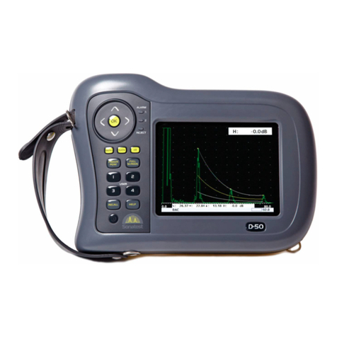
Sonatest Sitescan D-50 User manual
