Sonic Studio 300 Series User manual

Series 300
Eight Channel
User Manual
Sonic Studio

Page 2

Page 3
Table of Contents
Chapter 1 Overview .................................................................................................. 7
1.1 Features 7
1.2 Specifications .............................................................................................................................8
1.3 Requirements .............................................................................................................................9
1.3.1 Computer: ............................................................................................................. 9
1.3.2 Peripheral FireWire Adapter: .................................................................................. 9
1.3.3 Software: .............................................................................................................. 9
1.4 What’s Included ........................................................................................................................ 10
1.5 Additional Cabling .................................................................................................................... 10
1.6 Software Installation — Driver & Firmware ...........................................................................10
1.7 Support Information ................................................................................................................ 11
1.7.1 Warranty ............................................................................................................. 11
1.7.2 Registration ......................................................................................................... 11
1.8 Safety Compliance ...................................................................................................................12
Chapter 2 Hardware ............................................................................................... 15
2.1 Series 300 Front Panel .............................................................................................15
2.1.1 Status Display ........................................................................................... 15
2.1.3 Headphone ............................................................................................... 16
2.2 Making Connections ................................................................................................16
2.2.1 Analog Audio Connections ....................................................................... 16
2.2.2 Digital Audio Connections ........................................................................ 17
2.2.3 Telescoping Shield Cable for Instruments ................................................. 18
2.2.4 XLR to Balanced TRS Cable ...................................................................... 18
2.3 Integrated SRC .........................................................................................................18
2.4 Clock Sync .................................................................................................................18
2.5 FireWire ..................................................................................................................... 19
2.6 Power ........................................................................................................................20

Page 4
Chapter 3 Software ................................................................................................ 23
3.1 Sonic Console ...........................................................................................................23
3.1.1 Analog I/O Control Pane ........................................................................... 23
3.1.2 Mixer Pane ................................................................................................ 27
3.1.3 Mix/Output Routing Pane ......................................................................... 28
3.2 +DSP ..........................................................................................................................31
3.2.1 DSP Menu ................................................................................................ 32
3.2.2 Process Menu ........................................................................................... 33
3.2.3 Controlling Processes ............................................................................... 35
3.2.4 Patch Library Menu ................................................................................... 35
3.2.5 DSP Meter ................................................................................................ 35
3.2.6 Plug-in UI Specifics ................................................................................... 35
3.2.7 Examples .................................................................................................. 36
3.3 Recording Pane ........................................................................................................37
3.3.1 Controls & Indicators ................................................................................ 37
3.3.2 Recording & Playback ............................................................................... 37
Index .............................................................................................................. 103

Page 5

Page 6
©2007 Sonic Studio, LLC — All rights reserved
This manual, as well as the software described in it, is furnished under license and may only be used or copied in accordance
with the terms of such license. The information in this manual is furnished for informational use only, is subject to change with-
out notice, and should not be construed as a commitment by Sonic Studio, LLC. Sonic Studio, LLC assumes no responsibility or
liability for any errors or inaccuracies that may appear in this book.
Except as permitted by such license, no part of this publication may be reproduced, stored in a retrieval system, or transmitted,
in any form or by any means, electronic, mechanical, recording, or otherwise, without the prior written permission of Sonic
Studio, LLC.
SONIC STUDIO, LLC MAKES NO WARRANTIES, EXPRESS OR IMPLIED, INCLUDING WITHOUT LIMITATION THE IMPLIED WAR-
RANTIES OF MERCHANTABILITY AND FITNESS FOR A PARTICULAR PURPOSE, REGARDING THE APPLE SOFTWARE. SONIC
STUDIO, LLC DOES NOT WARRANT, GUARANTEE, OR MAKE ANY REPRESENTATIONS REGARDING THE USE OR THE RESULTS
OF THE USE OF THE SONIC STUDIO, LLC SOFTWARE IN TERMS OF ITS CORRECTNESS, ACCURACY, RELIABILITY, CURRENT-
NESS, OR OTHERWISE. THE ENTIRE RISK AS TO THE RESULTS AND PERFORMANCE OF THE SONIC STUDIO SOFTWARE IS AS-
SUMED BY YOU. THE EXCLUSION OF IMPLIED WARRANTIES IS NOT PERMITTED BY SOME STATES. THE ABOVE EXCLUSION
MAY NOT APPLY TO YOU.
IN NO EVENT WILL SONIC STUDIO, LLC, ITS DIRECTORS, OFFICERS, EMPLOYEES, OR AGENTS BE LIABLE TO YOU FOR ANY
CONSEQUENTIAL, INCIDENTAL, OR INDIRECT DAMAGES (INCLUDING DAMAGES FOR LOSS OF BUSINESS PROFITS, BUSI-
NESS INTERRUPTION, LOSS OF BUSINESS INFORMATION, AND THE LIKE) ARISING OUT OF THE USE OR INABILITY TO USE
THE SONIC STUDIO SOFTWARE EVEN IF SONIC STUDIO HAS BEEN ADVISED OF THE POSSIBILITY OF SUCH DAMAGES. BE-
CAUSE SOME STATES DO NOT ALLOW THE EXCLUSION OR LIMITATION OF LIABILITY FOR CONSEQUENTIAL OR INCIDENTAL
DAMAGES, THE ABOVE LIMITATIONS MAY NOT APPLY TO YOU.
Sonic Studio, Sonic Clarity, SSE, soundBlade and the Sonic Studio logo are trademarks of Sonic Studio, LLC. All other company
or product names are either trademarks or registered trademarks of their respective owners.
Created by Sonic Studio, LLC <www.sonicstudio.com>, using Mac OS 10, Adobe InDesign and the Univers family of typefaces.
We appreciate your comments and suggestions regarding this manual. Please contact us at <[email protected]>.
070913v1r3

Page 7
Chapter 1 ................................................................. Overview
Thank you for purchasing a Eight Channel Series 300 interface, the custom FireWire–based
professional audio interface from Sonic Studio. Series 300 DSP I/O Processors are portable,
high�quality, FireWire–attached, multi-format audio converter, interface, and processor for pro-
fessional audio applications. Your Series 300 provides an array of functions that allow you to
record and mix with unprecedented quality.
1.1 Features
All Eight Channel Models:
Purpose–built to run Sonic Studio’s soundBlade & NoNOISE II
Extended Precision 192 kHz 48 bit Signal Pathways
Patching Flexibility in Both Software & Hardware
Exceptional Embedded Processing
Chainable Isochronous FireWire Interface
Includes Graphing Version of Sonic Studio’s Minimal Phase EQ
High Quality Clock Master
Fully Portable Capabilities �— Bus and Battery Powerable
Eight channels of AES/EBU I/O
Sample Rate Conversion (SRC) on Digital I/O
Built-in 80 bit, Fully Interpolated, Multi-bus Mixer
Full Cross Point Router
Word Clock Input — 1x, 256x
Front Panel Metering
Full Software Metering
LTC I/O
Total Recall of Every Parameter
The Model 304 adds:
Eight Channels of Line Level Analog I/O
Outboard & Headphone Monitoring
•
•
•
•
•
•
•
•
•
•
•
•
•
•
•
•
•
•
•

Page 8
The Model 305 adds:
Eight Microphone Preamplifiers
1.2 Specifications
All Models:
Full 24 bit/192 kHz audio I/O
44.1 to 192 kHz sampling rates
Word clock I/O, 1x or 256x on BNC
SMPTE LTC I/O on 1⁄4” TRS
8 channels AES/EBU Type I digital I/O on XLR3
80 bit mixer and over two dozen types of plug–ins
DSP compliment: two ADSP-21065 + one ADSP-21364
Dual 6 pin FireWire 400 (IEEE 1394a) host connectors
Full Core Audio support for all Mac OS X applications
Defeatable asynchronous SRC on input
8 simultaneous inputs & outputs
Rack mount kit hardware included
Mains or battery powered
Model 304 adds
8 balanced analog +4 dBU analog sends on XLR3
8 balanced analog +4 dBU analog inputs, with trim, on XLR3
8 balanced analog +4 dBU analog monitor/line outputs on XLR3
2 balanced analog +4 dBU analog monitor outputs, 1⁄4” TRS
Stereo balanced analog send & return, 1⁄4” TRS
24 bit A/D converters, 116 dB unweighted, 120 dB A–weighted
24 bit D/A converters, 120 dB A–weighted
DSP: one ADSP-21364
Independent headphone output, 1⁄4” TRS
Model 305 adds
8 balanced analog +4 dBU analog preamp inputs on XLR3
•
•
•
•
•
•
•
•
•
•
•
•
•
•
•
•
•
•
•
•
•
•
•
•

Page 9
Switchable phantom on all 8 preamps
8 channels of high gain, low noise preamplification with power & optional Jensen
transformer coupling
Model 305 Microphone Input Specifications
Gain Range with Trim: -14 dB to +70 dB
Harmonc Distortion @ 1 kHz (+9 dBu in @ 6 dB Gain): 0.0005%
Intermodulation Distortion (1 kHz component, 19 kHz/20 kHz @ +8 dBu): -96 dBu
Equivalent Input Noise, 20 Hz–20 kHz Flat @ 72 dB Gain, 150 Ω Source: -130.5 dBu
Equivalent Input Noise, 20 Hz–20 kHz Flat @ 72 dB Gain, 0 Ω Source: -134.0 dBu
Frequency Response, 18 Hz–20 kHz: ± 0.1 dB
Frequency Response, 3 Hz–100 kHz: ± 3.0 dB
Crosstalk @ 1 kHz, trim link engaged: -107 dB
1.3 Requirements
1.3.1 Computer:
a G4 Macintosh or newer, with a FireWire Port and OS 9.1 or newer, Mac OS 9.2.2 and Mac OS
X recommended.
512 MB of RAM
1024x768 display or better
1.3.2 Peripheral FireWire Adapter:
OHCI compliant PC-Card or
OHCI compliant PCI card
1.3.3 Software:
an ASIO 2 or CoreAudio compatible host such as soundBlade, PreMaster CD, Cubase, Nuendo,
Logic or Digital Performer
for ASIO direct monitoring-based foldback and overdubbing, an application that supports ASIO
direct monitoring
•
•

Page 10
1.4 What’s Included
Your Series 300 Eight Channel package contains the following items:
One Series 300 unit (Model 303, 304 or 305)
One IEC mains or power cord, appropriate for your area
One 24 Volt, 48 Watt, world-ready external power supply
One 0.5 meter, IEEE 1394a, 6 pin FireWire cable
One Software Install CD, containing Sonic Console software, firmware and an
Extras folder
Rack Mount Kit
This Quick Start Guide
1.5 Additional Cabling
DB25 or DSub male to XLR or TRS cables to connect your Series 300 Interface to
your analog and digital equipment:
One DB25 to XLR female or TRS for 8 channels of audio input
One DB25 to XLR male or TRS for 8 channels of audio output
One DB25 to four XLR male plus four XLR female for 8 channels of AES digital input/
output
One DB25 to XLR female for 8 channels of microphone input (305 only)
Two 1/4” TRS male cables for L and R main outputs
One or two 110 Ω, BNC coaxial cable for word clock connections, if needed
One 110 Ω, BNC coaxial terminator for word clock connections, if needed
One 110 Ω, BNC “T connector” for word clock connections, if needed
One or two 1/4” TRS male and/or female cables for SMPTE/EBU LTC connections, if
needed
1.6 Software Installation — Driver & Firmware
Please load the included CD into your drive and carefully read the enclosed Series300_Read-
Me_Installing document. In addition, the CD contains specific instructions on the installation of
driver and firmware for your converter.
If you are using an Intel Mac as your host, please pay special attention to the Aggregate Audio
Device instructions.
1.
2.
3.
4.
5.
6.
7.
8.
•
•
•
•
•
•
•
•
•
•

Page 11
1.7 Support Information
1.7.1 Warranty
Series 300 hardware is covered by a manufacturer’s warranty against manufacturing defects.
The details of this warranty are described in a separate enclosed document. This warranty is
applicable to products purchased in the USA. Products purchased in other regions are covered
by a warranty administered by the distributor for that region and the terms will be as set forth
in a separate document.
1.7.2 Registration
In order to receive warranty service, you must register the product with Sonic Studio. This may
be done at any time with proof-of-purchase, but we strongly recommend that you register with
us as soon as you purchase your unit. There are a couple of practical reasons for this:
Your product will be registered with us and this registration can be used as proof of ownership
if your product is ever lost or stolen.
Sonic Studio aggressively updates the Model 302 on a regular basis and we would like to keep
you informed of critical updates as they become available.
In order to register your 302, please e–mail or fax the following information to:
775-330-8923 facsimile
Alternatively, if you have internet access you can use our automated registration webpage at:
http://www.sonicstudio.com/register
Service and Support
If you have problems configuring or using your 302 and you need help, please contact us. We
offer free support via e–mail, as well as peer support on the Sonic Studio Users Group and MIO
Users Group mailing lists.
For paid phone support, contact us at:
1-415-460-1201
For e–mail support, send email to:
suppor[email protected]
To subscribe to the Sonic Studio Users Group mailing list or to peruse the archives go to:
https://mail.music.vt.edu/mailman/listinfo/sonic
To subscribe to the MIO/302 Users Group mailing list or to peruse the archives go to:
https://mail.music.vt.edu/mailman/listinfo/mobileio

Page 12
Finally, you can always find the latest info and updates for your Model 302 at the Sonic Studio
website:
http://www.sonicstudio.com/support
1.8 Safety Compliance
This equipment has been tested and found to comply with the limits for a class B digital device
pursuant to part 15 of the FCC Rules. These limits are designed to provide reasonable protec-
tion against harmful interference in a residential installation. This equipment generates, uses,
and can radiate radio frequency energy and, if not installed and used in accordance with the
instruction manual, may cause harmful interference to radio communications. However, there
is no guarantee that interference will not occur in a particular installation. If this equipment
does cause interference to radio or television equipment reception, which can be determined
by turning the equipment off and on, the user is encouraged to try to correct the interference
by any combination of the following measures:
Relocate or reorient the receiving antenna
Increase the separation between the equipment and the receiver
Plug the equipment into an outlet on a circuit different from that to which the
receiver is connected
Consult your dealer or experienced radio/television technician for additional as-
sistance.
WARNING: Changes or modifications to this unit not expressly approved by the party respon-
sible for compliance could void the user’s authority to operate the equipment.
1.
2.
3.
4.

Page 13

Page 14

Page 15
Chapter 2 .................................................................Hardware
2.1 Series 300 Front Panel
The Series 300 front panel provides ten-segment metering for the eight inputs and the main
outputs. The meters are fast PPM peak reading meters with auto-resetting peak holds.
2.1.1 Status Display
The front panel also provides Series 300 system status at a glance:
2.1.1.1 Sample Rate
(nominal 44.1, 48, 88.2, or 96)
Since sample rate is determined by the currently selected clock source, it will accurately indi-
cate the current sample rate, even when the clock source is provided by an external device.
2.1.1.2 Clock source
Internal indicates that the system is internally clocked
Word clock indicates that system is being clocked from the word clock input
256x WC indicates that the system is being clocked from a 256x clock at the word clock input
Digital In indicates that the system is being clocked from the selected digital input (AES or
S/PDIF)
256x WC + Digital In indicates that the system is being clocked from the ADAT optical input
2.1.1.3 Power
Indicates that the Series 300 is receiving power.
2.1.1.4 FireWire
Indicates that the Series 300 has been successfully connected to a FireWire bus and has de-
tected the isochronous cycle required to transmit and receive audio.
2.1.1.5 Locked
Indicates that the system clock recovery circuit is properly locked to the selected clock source.
If this light is not illuminated, the Series 300 will not be locked to a clock and will revert to its
fail–safe internal clock source. Even if the Locked light is not illuminated, the actual sample rate
will still be indicated on the front panel display.

Page 16
2.1.2 Digital I/O Section
The AES and S/PDIF lights are mutually exclusive and indicate which of the two input ports are
feeding the Stereo Digital input of your Series 300. The Locked light indicates when the digital
receiver is locked to the incoming digital audio signal.
2.1.3 Headphone
The Models 304 and 305 front panels provide access to the Headphone output and its associ-
ated level control knob as well as level control for the monitor outputs which are located on the
back of the unit.
The headphone output is a TRS 1/4” jack that provides the Left Channel on the tip, the Right
Channel on the ring and the ground return for the two channels on the sleeve.
2.2 Making Connections
Depending on model, there are four or five classes of connections you can make to the hard-
ware:
Analog Audio (Models 304 & 305)
Digital Audio
Clock Sync
FireWire
Power
Connecting your Series 300 DSP I/O Processor to outboard equipment is easy. Where applica-
ble, always use balanced interconnects with your Series 300 unit. Please make sure that power
to your Series 300 DSP I/O Processor is off while making all connections.
2.2.1 Analog Audio Connections
Whenever possible, use balanced interconnects with Series 300 models. The performance of
balanced interconnects is much higher, with far more resistant to noise interference and AC
electrical or mains wiring problems. The expense of balanced interconnects is not substantially
higher than unbalanced cabling so, if the gear that you are interfacing with supports balanced
connection,�do make use of them. If you cannot utilize balanced interconnects, there are bal-
ancing transformer or active balancing stages that you can use that will maximize perfor-
mance.
2.2.1.1 Inputs for Model 304 and 305
Connect another analog DB25 cable assembly to the “Line In 1-8.” This connection is associat-
ed with analog inputs 1-8, Analog 1-Analog 8, in soundBlade, and can be connected to the line
outputs of any +4 dBU analog device.
1.
2.
3.
4.
5.
Page 17
2.2.1.2 Inputs for Model 305 Only
You may connect microphones directly your Model 305 Converter by attaching an analog DB25
to XLR male cable assembly to the inputs labeled “Mic In 1-8.”
Attach the power cord, but do not power up your converter at this time.
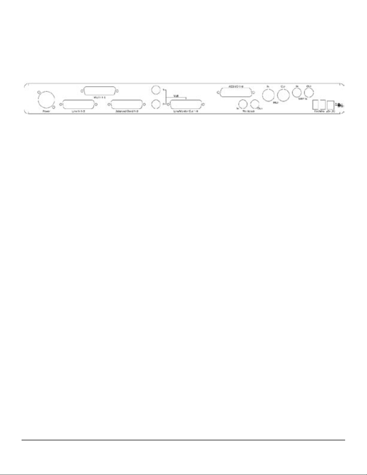
Figure 1 — Model 304 Back Panel Configuration
2.2.2 Digital Audio Connections
All Series 300 models support eight channels of AES Type I or balanced digital audio–over–
copper connections.
2.2.2.1 Input For All Models
For AES/EBU digital input, use the digital DB25 cable assembly you connected earlier to your
unit’s AES connector labeled “AES I/O 1-8,” and attach the XLR female connectors to the out-
puts of your outboard AES device(s). These are associated with digital inputs 1-8, Digital In
1-Digital In 8, of soundBlade.
2.2.2.2 Output For All Models
For AES digital output, connect your digital DB25 cable assembly to your unit’s AES connector
labeled “AES I/O 1-8,” then attach the four XLR male connectors to the inputs of your outboard
AES device(s). These are associated with the digital outputs of soundBlade.
2.2.2.3 Output for Model 304 and 305 Only
Use the 1/4” balanced TRS “Multi” outputs to connect your unit to a stereo input on your
mixer, typically the main stereo input. The top connector is channel 1 or Left, usually being fed
from Mix Bus M1 in soundBlade, while the bottom connector is channel 2 or Right, which is
usually being fed from Mix Bus M2 in soundBlade.
Note: This is the same output signal you will find present on channels 1 and 2 of the associated
multichannel DB25 connector labeled “Line/Monitor Out 1-8.”
Connect your analog DB25 cable assembly to the “Line/Monitor Out 1-8” on the back of your
converter. This is the DB25 connector in the center of the unit’s back panel, and it is fed from
the Mix Buses M1-DAW 1 through M8-DAW 8 in soundBlade.
Using the connectors that are appropriate for your mixer, plugging them into eight input
channels on your mixer. This set up provides for the monitoring of the M1-M8 outputs in

Page 18
soundBlade as well as some additional functionality, surround monitoring in 4.1, 5.1 and 7.1
formats and the creation of multiple headphone mixes using the included Sonic Console appli-
cation.
When you connect a 1/4” plug to a Series 300 jack, insert it straight and firmly, ensuring that
the plug is fully inserted into the jack. If the plug is not fully inserted you will get level shifts,
phase flips, distortion, or no sound.
2.2.3 Telescoping Shield Cable for Instruments
If you want to use the analog inputs with TRS–equipped devices, you may need an XLR to 1/4”
TRS balanced plug adapter cable. These are available commercially, or you can construct one
easily. The connections are Tip to Pin 2, Ring to Pin 3 and Sleeve to Pin 1.
2.2.4 XLR to Balanced TRS Cable
On output, if you are driving an unbalanced load, you will get the best performance by not
connecting the ring of TRS jacks to ground. In order to do this, you can simply use a balanced
TRS/TRS connector with the unbalanced gear. You can also construct a special cable with a TRS
connector and a TS connector. In this cable, you just let the ring of the TRS connector float.
Alternatively, the TS connector can be replaced with an RCA connector for interfacing with
gear that has RCA unbalanced interconnects.
2.3 SRC
Normally, when working with digital audio transport, you must take care to ensure that all de-
vices communicating with one another are synchronized to the same audio clock. While this is
still an important consideration with the Series 300, the hardware provides a special feature to
simplify copper-based digital connections to the box. The Series 300 digital inputs have an op-
tional asynchronous sample rate converter (SRC) that will automatically match the sample rate
of the incoming audio to the sample rate of the hardware. This converter is enabled by default
and you should disable it in the System section of the Sonic Console. If you have synchronized
the Series 300 to the external source, using any of the extensive synchronization methods pro-
vided, you will generally want to disable the SRC in order to get 24 bit transparent transport via
the digital inputs.
2.4 Clock Sync
Clock sync is a serious consideration in any digital audio system. If you are recording analog
sources with your Series 300, you can simply use the unit’s high-quality internal clock source to
drive the converters. This is the easiest method.
If you need to interface with other devices digitally or ensure sample accurate sync with video
sources, the extensive clock synchronization capabilities will prove to be more reliable and bet-
ter sounding than most higher priced alternatives.
There are three different ways to get external clock information into the unit:

Page 19
Sending a 1x word clock signal into the BNC WC Input.
Sending a 256x word clock signal into the BNC WC Input.
Sending an AES/EBU or S/PDIF signal into the Digital input.
The BNC word clock input port is a 110 Ω internally terminated coaxial input. It should be
driven by a 110 Ω source driver and interconnected with 110 Ω coaxial cable. If you do not use
proper cabling and source drive, you will introduce reflections on the word clock cable which
will propagate jitter into the recovered word clock and your final output. This is true whether
you use the port as a 1x WC input or a 256x WC input, but becomes more important when the
clock signal is 256x.
1x is generally appropriate for use with devices that provide a word clock output. If your de-
vice provides a 256x output, you may find that you get better results using that clock signal.
The Digidesign© line of Pro Tools© products use 256x as their “Superclock” clocking reference.
The AES recommended procedure for distributing clock is to use an AES clock signal. The AES
clock signal is an AES digital audio signal with no audio activity. Series 300 models uses only
the AES preambles for clock recovery, so it is immune to data–dependent jitter effects. This
means you can reliably use the Digital Input as a clock source with or without audio data.
2.5 FireWire
FireWire© is Apple’s registered trademark for the IEEE 1394 high speed serial bus. FireWire
started as an Apple technology to replace a variety of interface ports on the back of the com-
puter. After promulgating a number of closed proprietary technologies in the early days of the
Macintosh, Apple determined that open standards were better for the Mac, for the industry,
and for Apple itself. On that basis they opened their technology for standardization under the
auspices of the Institute of Electrical and Electronics Engineers, Inc. (IEEE), an international
organization that promotes standards in the field of electronics. FireWire was standardized as
IEEE 1394 and promoted for open licensing in the industry.
The first widespread adoption of the technology was for DV camcorders where space was
at a premium and bus powering was not percieved as a real issue since all camcorders have
batteries. Sony designed an alternative version of the standard 6 pin FireWire connector that
provided 1394–based communication with 4 pins in a much smaller form factor. This version of
the connector sacrificed bus power support and mechanical stability for reduced space require-
ments. Sony dubbed this version “i.Link©.” This became the de facto standard in the DV world,
and was later added to the IEEE 1394 standard. Both i.Link and FireWire refer to the same un-
derlying standard and are completely interoperable. Obviously, i.Link connectors and FireWire
connectors cannot be used together without adapters.
Series 300 models uses the 6 pin implementation of FireWire for bus power support. The unit
ships with a 0.5 meters long, about 18 inches. If you want to use your Series 300 with a 4 pin
FireWire device, you will need to purchase a 6 pin to 4 pin adapter cable. These cables are
available from a wide variety of retail sources. If you are using a 4 pin cable to connect any
device to the computer with Series 300 models, bus power will not be available.
The 6 pin FireWire connector is keyed by its shape, as one end of the connector is pointed. The
FireWire ports on Series 300 models point downwards toward the bottom of the box. It will be
very difficult to insert the connector upside down, but it is possible if you force it. If the plug is
1.
2.
3.

Page 20
inserted into the socket upside down, the socket will be destroyed. Never force a FireWire con-
nector into a FireWire socket!
Devices connected to the FireWire bus are auto–configuring. You do not need to set IDs, DIP
switches or in any way configure the devices in order to facilitate communication between de-
vices or to configure of the bus.
FireWire devices on the same bus must be connected in a tree structure with no loops. This
means that devices can be connected to each other in any order, and any device with multiple
ports can act as a chain or a hub for other FireWire devices, but you should never be able to
get from one device to another by more than one path. If you construct a loop in the bus, it will
not operate properly and you will not be able access some or all of the devices on the bus.
Although you are able to attach devices in any order on the FireWire bus, the order of attach-
ment will have an impact on performance. Most current model FireWire devices support 400
Mbs operation, but many older devices may only support 100 or 200 Mbs operation. These
devices act as a bottleneck in the bus and limit the speed of any bus traffic that flows through
them. In order to maximize performance, you want to ensure that low speed devices are not
used to join high speed devices. In practice this generally means that you should attach your
302 directly to your computer or through a high speed FireWire hub.
To connect your Series 300 to your computer, simply interconnect the unit and the computer
with a FireWire cable. The FireWire bus provides a path for all communications between the
computer and the Series 300: audio, control and metering data.
The Series 300’s audio transport takes advantage of FireWire’s support for isochronous trans-
mission, in which the 300 can reserve a dedicated amount of bandwidth on the bus for moving
audio samples. Since the audio must be transmitted on a regular basis to ensure continuous
playback and recording, the isochronous mode is ideally suited to this task.
Control changes and meter data are transmitted using asynchronous transactions on the
FireWire bus. This transmission approach makes use of the unreserved bandwidth on the bus
and competes with processes like FireWire hard disk access for time. Under normal circum-
stances, this is completely transparent to the user. If the bus becomes overloaded, you may
find that disk accesses and meter updates slow down. If you are experiencing bus overloads,
you can always add a second FireWire bus with a third-party Host Bus Adapter or HBA. An
HBA, either PC-Card or PCI depending on your machine, will offload one or more devices to the
second bus.
2.6 Power
Series 300 models ship with a world-ready, 24 volt, 2 amp power supply. You can plug this
supply into any AC power source from 90 to 240 VAC, 50 to 60 Hz, using an appropriate IEC
power cord.
As with all electronic devices, when connecting an external power source to any Series 300
model, you should first connect the power source to 300 while it is in an unenergized state, not
connected to the mains or switched off. After the connection to the 300 has been made, you
should energize the power source.
This manual suits for next models
4
Table of contents


