Soniclean S2800 User manual

Maintenance Manual
S-2800
Soniclean Irrigated Ultrasonic Cleaner
Version 1 July 2006
So Easy So Fast So Clean
So
ni
clean
SONICLEAN PTY LTD
ABN 89 057 730 917 ACN 057 730 917
38 Anderson Street, Thebarton, South Australia, 5031
Tel: 61 + 8 + 8234 8398 Fax: 61 + 8 + 8234 8391

__________________________________________________________________________________
S-2800 Irrigator Maintenance Manual Page 2 of 55
© Soniclean Pty Ltd Version 1 July 2006
Contents
1. Overview............................................................................................................................................ 4
2. Installation Requirements................................................................................................................ 6
2.1. Environmental:.............................................................................................................................. 6
2.2. Plumbing:...................................................................................................................................... 6
2.3. Electrical:...................................................................................................................................... 6
2.4. Machine Reporting System: (MRS models only)......................................................................... 6
2.5. Printer: (MRS & printer or printer only models).......................................................................... 6
2.6. Detergent Bottle:........................................................................................................................... 6
2.7. Machine Location: ........................................................................................................................ 6
2.8. Ambient Temperature Sensor ....................................................................................................... 7
3. Tools................................................................................................................................................... 7
4. Specifications..................................................................................................................................... 8
5. Installation......................................................................................................................................... 9
5.1. Plumbing:..................................................................................................................................... 9
5.2. Electrical:..................................................................................................................................... 9
5.3. Machine Reporting System: (MRS only) .................................................................................... 9
5.4. Printer. (MRS only) ..................................................................................................................... 9
5.5. Detergent Bottle:.......................................................................................................................... 9
5.6. Machine Location: ....................................................................................................................... 9
6. Commissioning................................................................................................................................ 10
6.1. Check Installation: ..................................................................................................................... 10
6.2. Mains Inlet Water Supply:......................................................................................................... 10
6.3. Detergent:................................................................................................................................... 10
6.4. Mains Electrical Supply:............................................................................................................ 10
6.5. Machine Reporting System: (MRS only) .................................................................................. 10
6.6 Printer. (MRS only) ................................................................................................................... 10
6.7. Start-up Routine:........................................................................................................................ 10
6.8. Ultrasonic Performance Tests:................................................................................................... 10
7. De-commissioning........................................................................................................................... 11
7.1. Disinfect the machine: ............................................................................................................... 11
7.2. Mains Inlet Water Supply:......................................................................................................... 11
7.3. Drain Machine: .......................................................................................................................... 11
7.4. Pack for Servicing:..................................................................................................................... 11
8. Maintenance Procedures................................................................................................................ 12
8.1 Level Sensor Adjustments using a computer:.............................................................................. 12
8.2 Level Sensor Adjustments manually: ......................................................................................... 15
8.3. Disinfecting Machine:................................................................................................................ 15
8.4. Drain Stainless Steel Tank:........................................................................................................ 16
8.5. Foil Test Procedure:................................................................................................................... 17
8.6. Browne Test Procedure:............................................................................................................. 18
8.7. Browne STF Load Check: ......................................................................................................... 19
8.8. Special Test Pencil Test:............................................................................................................ 19
8.9. LumCheck Test:......................................................................................................................... 19
8.10. Leak Inspection:........................................................................................................................ 19
8.11. Water Source Flow Rate Measurement: ................................................................................... 20

__________________________________________________________________________________
S-2800 Irrigator Maintenance Manual Page 3 of 55
© Soniclean Pty Ltd Version 1 July 2006
8.12. Water Source Pressure Measurement: ...................................................................................... 20
8.13. Water Source Hardness Measurement:..................................................................................... 20
8.14. Venturi Valve Information........................................................................................................ 20
9. Programming................................................................................................................................... 21
9.1 Programmable Features ............................................................................................................... 21
9.2 Keypad Description ..................................................................................................................... 22
9.3 Program Mode ............................................................................................................................. 23
9.4 Display Messages........................................................................................................................ 24
10. Scheduled Servicing and Preventative Maintenance................................................................. 25
11. Disassembly / Reassembly Procedures........................................................................................ 26
11.1. Acrylic Lid:............................................................................................................................... 26
11.2 Rear Inspection Cover................................................................................................................ 27
11.3. Digital Display and Keypad:..................................................................................................... 28
11.4. Digital Display Enclosure......................................................................................................... 29
11.5. Control Box Enclosure.............................................................................................................. 30
11.6. Ultrasonic Drivers Enclosure.................................................................................................... 31
11.7. Fill and Irrigation Solenoid Valves........................................................................................... 32
11.8. Detergent Solenoid Valve......................................................................................................... 33
11.9. Junction Box Enclosure. ........................................................................................................... 34
11.10. Level Sensor Enclosure........................................................................................................... 35
11.11. Mains and Waste Water Plumbing. ........................................................................................ 36
11.12. Motor Actuated Ball Valve..................................................................................................... 37
11.13. Stainless Steel Tank................................................................................................................ 38
11.14. Venturi Valve.......................................................................................................................... 39
12. Troubleshooting Guide................................................................................................................. 40
12.1. Program Values Lost: (FAIL)................................................................................................... 40
12.2. Low Level in Tank: (LO).......................................................................................................... 40
12.3. Drain Blocked: (drnb)............................................................................................................... 40
12.4. Overflow Detection: (OFLO) ................................................................................................... 41
12.5. Ultrasonics Overheating: (HOT)............................................................................................... 41
13. Fee for Service............................................................................................................................... 41
14. Plumbing Schematics.................................................................................................................... 42
15. Electrical Schematics..................................................................................................................... 44
16. Level Sensor Schematics................................................................................................................ 53
17. Parts List......................................................................................................................................... 54

__________________________________________________________________________________
S-2800 Irrigator Maintenance Manual Page 4 of 55
© Soniclean Pty Ltd Version 1 July 2006
1. Overview
The S-2800 Irrigated Ultrasonic Cleaner or “Irrigator” is designed to improve the quality and
consistency of cleaning of laparoscopic instruments using a combination of ultrasonics and irrigation.
The Irrigator flushes clean solution through the cannulae of hollow instruments, whilst delivering
ultrasonics to precision clean. The Irrigator is designed for cleaning hollow instruments and is equally
effective for cleaning non-cannulated instruments. It is intended that the instruments shall be gross
cleaned prior to loading into the Irrigator, and be sterilised in the usual manner after ultrasonic cleaning.
The S-2800 Irrigated Ultrasonic Cleaner has been specifically designed to fill to the correct level and
drain the stainless steel tank automatically. The soap will also be introduced to the water automatically
to the desired concentration.
A number of features have been added to the “Irrigator” to help operators validate the ultrasonic cleaner
of instruments as well as documentary evidence that instruments have been through a clean process.
This documentary evidence can be downloaded onto a laptop computer at the unit’s site or be channelled
through the LAN network to the department’s desktop computer or an instantaneous printout can be
generated via a printer option.
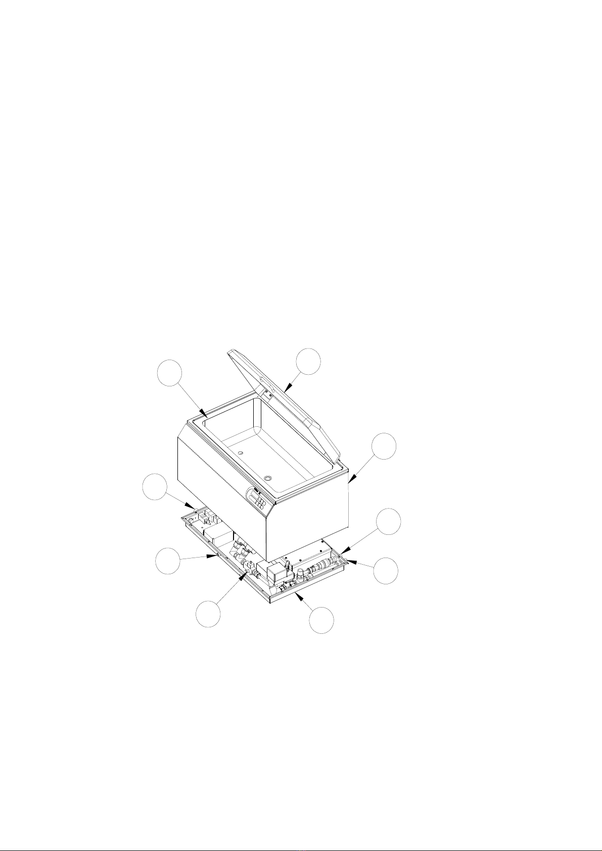
The S-2800 Irrigated Ultrasonic Cleaner consists of 4 major Sub Assemblies and 5 Connection Points.
Refer to Figure 1.
Sub Assemblies
1. Acrylic Lid
2. Stainless Steel Tank
3. Case
4. Plumbing Base
5. Tray
6. Control Enclosure
7. Ultrasonic Enclosure
Connection Points
8. Diagnostic Computer Connection
9. Printer Connection (Optional)
10. Ambient Temperature Sensor (Optional)
11. Machine Reporting System (Optional)
12. Detergent Connection
13. Mains Water Connection
14. Drain Connection
15. Soap Injection Adjustment
The Irrigated Ultrasonic Cleaner requires a flat horizontal location within maximum 2 degree tilt. The
unit should be positioned at operator’s convenient height. The bench should be strong enough to support
the machine fully loaded, with a person leaning on it. A distance of 100mm should be allowed at the
back of the machine to enable plumbing access. This can be reduced by fitting elbows to both the inlet
and the outlet.
__________________________________________________________________________________
S-2800 Irrigator Maintenance Manual Page 5 of 55
© Soniclean Pty Ltd Version 1 July 2006
Scheduled Servicing (see Section xx of this manual) is required to maintain the working efficiency of
the machine.
If corrective maintenance is required, Service Personnel can refer to the Troubleshooting Guide in
section xx of this manual to diagnose the fault and determine what corrective action is necessary.
This manual is provided as a reference for Maintenance personnel. It assumes that the personnel are
technically competent and have received instruction and training on the basics of ultrasonic equipment.
The manual includes Warnings and Cautions that are highlighted in red and must be observed by
personnel to ensure that personal safety is not compromised and damage to the Irrigated Ultrasonic
Cleaner does not occur.
The manual includes Notes that are highlighted in blue and recommend them to be observed by
personnel
1
7
8
3
4
9
5
6
2
Figure 1

__________________________________________________________________________________
S-2800 Irrigator Maintenance Manual Page 6 of 55
© Soniclean Pty Ltd Version 1 July 2006
2. Installation Requirements Note
The customer shall ensure the following requirements are met prior to installation. This is
essential for the machine to perform at optimum level. If the customer fails to provide this
information, the information shall be obtained on a Fee for Service arrangement.
2.1. Environmental:
i) Use cold water only.
ii) A tap or inlet must be dedicated to the irrigator.
iii) Water Quality for cleaning as per AS/NZS 4187:2003 shall be used. +Water Hardness will
determine the type of detergent to be used. It will also determine the amount of detergent to be
used in the cleaner.
2.2. Plumbing:
i) Maximum water pressure 150 psi, minimum water pressure 50 psi.
ii) Flow rate 10 litres/minute (minimum) to 20 litres/minute (maximum).
iii) This is a High Hazard application and the inlet mains supply shall be fitted with an approved
Reduced Pressure Zone Device and a line filter. (Please check with your local Water Authority
for the correct installation information for your area.)
iv) Mains inlet connection with ½” male bsp fitting within 600mm from the machine.
v) Do not use any aeration devices in the mains water supply.
vi) Outlet pipe of 25mm diameter for waste water within 600mm from the machine.
2.3. Electrical:
i) Wall power socket 240 VAC 50-60 Hz rated at 10 amps.
ii) Wall power socket located within 600mm from the machine.
iii) Power supply circuit shall not be shared with life threatening or life support electrical systems.
iv) Power supply circuit shall not be shared with computer electrical system or other excessively
large power devices, e.g. steriliser/washer disinfectors.
v) Earth leakage protection shall be provided by user.
2.4. Machine Reporting System: (MRS models only)
i) Local Area Network (LAN) outlet 1000mm from the machine.
2.5. Printer: (MRS & printer or printer only models)
i) Allow room on the left hand side of the machine for the printer unit.
2.6. Detergent Bottle:
i) The detergent bottle is supplied with your machine.
ii) The detergent bottle shall be positioned beside your machine.
iii) When bottle is empty replace with the same brand of detergent. It is important the identical
detergent is used, as this is critical to the total cleaning process. If other detergent is used the
machine shall require re-programming.
2.7. Machine Location:
i) Place the machine on a flat and horizontal surface. (Maximum 2º tilt)
ii) Position at operator’s convenient height. (The top of the lid at elbow height)

__________________________________________________________________________________
S-2800 Irrigator Maintenance Manual Page 7 of 55
© Soniclean Pty Ltd Version 1 July 2006
iii) The bench top shall be strong enough to support the fully loaded machine. (60 kg)
iv) The unit requires 590mmx 880mm of bench space.
v) Allow minimum 100mm clearance at the rear to enable plumbing access. This may be reduced
by fitting elbows to both the inlet and the outlet.
vi) Allow 1000mm clearance above unit to allow the lid to open fully.
2.8. Ambient Temperature Sensor
i) Ambient Temperature Sensor probe is supplied with your machine
ii) Ambient Temperature Sensor probe is plugged into the left hand side of the machine.
WARNING
Irrigators are used for cleaning surgical instruments that are contaminated with human blood and
body fluids. These contaminants could be an infection risk to maintenance staff.
WARNING
Power supply circuit shall not be shared with life threatening or life support electrical systems.
WARNING
Power supply circuit shall not be shared with computer electrical system or other excessively large
power devices, e.g. sterilizer/washer disinfectors.
WARNING
Surge Arrester shall be installed.
WARNING
Earth leakage protection (RCD) shall be provided by user.
3. Tools
Tools required for servicing the Irrigator.
Torch.
Screwdrivers, 4inch and 6inch, Straight and Phillips head.
Adjustable Spanners, 4inch, 6inch and 10inch.
Pliers, 6inch Pointy Nose and 6inch Bull Nose.
Spanner, Open Ended, 12mm, 10mm, and 8mm.
Multi-grips, 300mm.
Magnet.
Roll of home brand Aluminum Foil.
Neutral or Alkaline Silicon.
Metholated Spirit.
Tissue Paper and Rags.
__________________________________________________________________________________
S-2800 Irrigator Maintenance Manual Page 8 of 55
© Soniclean Pty Ltd Version 1 July 2006
4. Specifications
DIMENSIONS:
Model S-2800
Tank Size 650mm x 336mm x 180mm
Tank Capacity 39 litres
Ultrasonic Power 350W (typical)
Overall Size 742mm x 483mm x 420mm
Weight 35kg (approx)
Benchtop Footprint 590mm deep x 880mm wide x 790mm Overhead Clearance
ELECTRICAL:
240VAC 50Hz. 5.4 Amperes
DETERGENT TYPE:
Sonic 1
CAPACITIES:
Tank: 28 litres
Detergent: 5 litre separate container
WATER SUPPLY:
Maximum water pressure 150 psi, minimum water pressure 50 psi.
Flow rate 10 litres/minute (minimum) to 20 litres/minute (maximum).

__________________________________________________________________________________
S-2800 Irrigator Maintenance Manual Page 9 of 55
© Soniclean Pty Ltd Version 1 July 2006
5. Installation
5.1. Plumbing:
Inlet Mains Supply
i) Screw supplied braided hose on to the machine and inlet mains water supply.
ii) Hand tightened only.
Outlet Waste Supply
i) Screw and hand tighten supplied grey flexible drain hose on to the machine and insert into drain.
Ensure the grey flexible drain hose is installed with a gradual fall, from the machine to the drain.
Do not allow any loops to form in the hose.
5.2. Electrical:
i) Install surge protector.
ii) Plug machine into mains supply.
iii) Switch on when ready to operate.
5.3. Machine Reporting System: (MRS only)
i) LAN connection; take the LAN cable provided and push the black plug into the MRS socket
provided on the Irrigator. Plug the other end (RJ45) into the LAN wall outlet.
ii) Contact your IT department and hand them the Machine Reporting Manual. The appropriate
information for connecting the machine to the Local Area Network is found on page 10
“Network Hardware and Configuration” of the Machine Reporting System Manual.
iii) PC Connection: take the PC cable provided and push the black plug into the MRS socket
provided on the Irrigator. Plug the other end (RJ45) into the appropriate outlet on the PC.
iv) Temperature Sensor: Push the ambient temperature sensor probe into the temperature sensor
socket found on the right side of the machine.
5.4. Printer. (MRS only)
i) Plug the machine into mains supply and turn on at the switch.
ii) Plug the printer cable into the machine and the printer.
iii) Press the feed button to progress the paper.
5.5. Detergent Bottle:
i) Connect detergent hose to left hand side socket of machine.
ii) Place filtered end of detergent hose into container.
iii) Ensure there is sufficient detergent in bottle at all times.
iv) Each fill uses approximately 120ml of detergent (Sonic 1).
v) Check level of detergent regularly.
5.6. Machine Location:
i) Place machine on flat and horizontal surface (maximum 2º tilt).
ii) Position at operator’s convenience.

__________________________________________________________________________________
S-2800 Irrigator Maintenance Manual Page 10 of 55
© Soniclean Pty Ltd Version 1 July 2006
6. Commissioning
6.1. Check Installation:
i) Check that the Installation Procedure has been completed.
6.2. Mains Inlet Water Supply:
i) Check that mains inlet supply is turned on.
ii) Check that mains inlet valve is turned on.
6.3. Detergent:
i) Position detergent bottle beside the machine.
ii) Remove detergent bottle cap.
iii) Place the filter end of the detergent filler tube into the bottle. Slide the ceramic weight along the
tube to ensure the filter sits near the bottom of the bottle.
6.4. Mains Electrical Supply:
i) Check that AC mains electrical supply is 240V AC 10 amps.
ii) Turn on the mains electrical supply switch.
iii) Check the machine digital display shows SC2.1, then flashes P-UP. (power up)
iv) Ensure surge protector installed.
6.5. Machine Reporting System: (MRS only)
i) Temperature Sensor: Push the ambient temperature sensor probe into the temperature sensor
socket found on the right side of the machine.
6.6 Printer. (MRS only)
i) Check that the machine is plugged into mains supply and turn on at the switch.
ii) Plug the printer cable into the machine and the printer.
iii) Check that a roll of paper and printer ribbon has been installed
iv) Press the feed button to progress the paper.
6.7. Start-up Routine:
i) Turn on machine at the wall, the machine will drain, flush and drain, then fill with water and
detergent at the required concentration.
ii) De-gas cycle starts automatically after the machine has filled.
iii) Machine will display (- - - -) when ready for use.
6.8. Ultrasonic Performance Tests:
6.8.1 Foil Test Routine
i) Perform foil test as set out in Section 8.4
ii) The foil should have even, scattered perforations, not just scant, large perforations.
iii) If foil test passes, proceed with use of the machine.
iv) If test piece has inadequate perforations, (refer to xx Foil Test Problem Solving) repeat the de-
gas cycle, as excess gas in the water decreases the efficiency of the ultrasonics.

__________________________________________________________________________________
S-2800 Irrigator Maintenance Manual Page 11 of 55
© Soniclean Pty Ltd Version 1 July 2006
v) Repeat the test and if successful, proceed with use of the machine.
vi) If foil test fails again, refer to Section xx. (problem solving ideas)
vii) Foil test times may differ slightly in customer trials due to variables such as: detergent type,
water quality and temperature. Without the tray, Soniclean’s Irrigator foil test is typically 15
seconds. With the tray in place, the foil test time may be longer.
6.8.2 Aluminium Disc Routine
i) Lightly pencil the Aluminium Disc with the appropriate pencil.
ii) Suspend the Aluminium Disc onto the holder.
viii) All the lead will be removed in 2 to 3 seconds.
6.8.3 Browne Test Routine
i) Perform the Browne Test as set out in Section 8.5
7. De-commissioning
7.1. Disinfect the machine:
i) Refer Section 8.2
7.2. Mains Inlet Water Supply:
i) Turn off mains supply
ii) Remove screw-on connector slowly to relieve mains pressure and remove the flexible hose
coupling.
7.3. Drain Machine:
i) To empty bath – remove instrument tray and press “SHIFT” and “DRAIN” key together and hold
down for 3 seconds. Wait for machine to drain.
ii) Use syringe to suck up residual water in the port at the bottom of the tank.
iii) Plug the drain with a sponge.
iv) Wipe the inside of the tank dry.
v) Gently wipe the lid with a soft cloth to prevent scratching.
vi) Turn off at power point. Unplug the power cable from the mains outlet.
vii) Disconnect all other hoses i.e. outlet & detergent hoses.
viii) If the machine needs to be relocated, do not attempt to lift it unaided.
7.4. Pack for Servicing:
i) Remove rear inspection cover
ii) Locate the brass flow restrictor device on the plumbing line. Undo the small flat brass screw on
the flow restrictor device until a small amount of water flows from the screw. Catch the water
with a tissue or suitable cloth.
iii) The water retained in the plumbing system should flow out through the normal
drain.
iv) Slightly raise the right hand end (looking from the back) of the irrigator
v) Retighten the flat brass screw on the flow restrictor device
vi) Replace the rear inspection cover.
v) Use packing materials supplied or nominated by the manufacturer or authorised agent.
vi) Use freight courier nominated by the manufacturer or authorised agent.

__________________________________________________________________________________
S-2800 Irrigator Maintenance Manual Page 12 of 55
© Soniclean Pty Ltd Version 1 July 2006
+WARNING
The machine weighs >35 kg and requires at least two persons to lift.
CAUTION
Do not use personal discretion in performing packaging tasks.
The machine requires utmost care during handling, packing and shipping.
8. Maintenance Procedures
8.1 Level Sensor Adjustments using a computer:
Procedure:
Location:
The adjustment potentiometers are mounted on the Level Sensor PCB.
Equipment Required:
The Level Sensor enclosure is mounted in between the left hand side wall of the tank and the main
enclosure looking through the inspection opening at the rear of the machine. It is held in place with
Velcro strips.
Pull the Level Sensor enclosure down and away from the main enclosure wall and pull it outside the
machine as far as it can go.
CAUTION
Do not dismantle the electrical cable or clear plastic tube attached to the Level Sensor enclosure
On the rear of the enclosure, unscrew the four Philip Head screws.
Using a Stanley knife carefully cut through the silicon seal and remove the cover.
You can observe the four multiturn trimpots appropriately marked RV1, RV2, RV3, RV4.
Attach the Level Sensor enclosure to the rear wall of the main enclosure at roughly the same height as
the working Level Sensor enclosure with masking tape. Ensure the exposed Level Sensor PCB is
exposed for adjustment.
Follow the Work Instruction entitled Level Sensor Adjustment.
Computer with a serial port, and Irrigator Utilities (io.EXE).
Note
Level #1 must be adjusted first before adjusting any of the other levels.
If level #1 is changed then all the other levels will need to be re-adjusted.
These adjustments assume that multiturn trimpots are used for RV1, RV2, RV3, RV4 and no
RV1A is used.
The trimpots may be adjusted quickly to find the actual point of change then the trimpot should
be backed off and re-adjusted slowly for level indication.

__________________________________________________________________________________
S-2800 Irrigator Maintenance Manual Page 13 of 55
© Soniclean Pty Ltd Version 1 July 2006
Computer Setup Information
At prompt: C:\>_
Power to the unit should be off
Connect Diagnostics cable to a PC and the Irrigator
Computer needs to be in WINDOWS mode.
Go into EXPLORER and double click on the IO.EXE program.
Follow the prompt and answer the questions as per sample below:-
1) Com1; press 1and enter
2) Is the unit in SLAVE CONTROL MODE [y/n] type n
3) Proceed now? [y/n] type y
4) Turn power onto the unit
The following screen will be displayed. Use this program to fill the unit and set the levels on the level
sensor enclosure.
3) Use arrow keys to move white highlight cursor to each function. The cursor only highlights the
bottom segment of components. Press space bar to activate the function. Press again to
deactivate.
Terminology Upper Section:-
LEVEL 1- Bottom level sensor setting. Take a measurement of 60mm from the centre of tank to the
water height to attain the correct measurement.
LEVEL 2:- Operating level sensor setting. Take a measurement of 125mm from the centre of the
tank to the water height.
LEVEL 3 Irrigator level sensor setting. Take a measurement of 140mm from the centre of the tank
to the water height.
WLDSTA:- Lid status. If the lid is open screen will indicate [YES]. If the lid is closed screen will
indicate [OFF].
OFLOW:- Overflow level sensor setting. Measure 175mm from the centre of the tank to the height
of water
LEVEL 1 LEVEL 2 LEVEL 3 ------- -------- -------- -------- --------
ON ON ON ON ON ON ON ON
WLDSTA --------- LEAK OFLOW -------- -------- -------- --------
ON ON ON ON ON ON ON ON
_______________________________________________________________
----------- CWSFIL WSHFIL IRRFIL SOPFIL -------- -------- --------
OFF OFF OFF OFF OFF OFF OFF OFF
------- ------ PUMP DRAIN ---------- -------- -------- --------
OFF OFF OFF OFF OFF OFF OFF OFF

__________________________________________________________________________________
S-2800 Irrigator Maintenance Manual Page 14 of 55
© Soniclean Pty Ltd Version 1 July 2006
Terminology Lower Section:-
CWSFIL:- When highlighted and the space bar is pressed, opens the solenoid valve positioned between
the pressure reducing valve and the venturi valve. WARNING: This valve needs to be open before the
WSHFIL and IRRFIL solenoid valves are opened.
WSHFIL:- When highlighted and the space bar is pressed opens the solenoid valve that fills the tank.
IRRFIL:- When highlighted and the space bar is pressed opens the solenoid valve that can fill the tank as
well. Warning: Don’t operate this valve without a baffle over the irrigation spigot. Water will spray
everywhere if not careful
SOPFIL:- When highlighted and the space bar is pressed opens the solenoid valve that allows detergent
to be injected into the tank while the WSHFIL or IRRFIL is open.
PUMP:- When highlighted and the space bar is pressed operates the pump. When open press space bar
to deactivate the process.
DRAIN:- When highlighted and the space bar is pressed opens and closes the drain solenoid valve.
Level #1 (LEVEL 1) setting (RV1).
Fill tank with liquid to depth required for level #1. Water height at Level # 1 shall be 60mm measured
in the centre of the tank.
If Level #1 (WSHMIN) indicator is lit then turn RV1 clockwise quickly until indicator turns off.
Turn RV1 slowly anti-clockwise until indicator level #1 just lights.
Level #2 (LEVEL 2) setting (RV2).
Fill tank with liquid to depth required for level #2. Water height at Level # 2 shall be 125mm measured
in the centre of the tank.
If Level #2 indicator is lit then turn RV2 anti-clockwise quickly until indicator turns off.
Turn RV2 slowly clockwise until indicator level #2 just lights.
Level #3 (LEVEL 3) setting (RV3).
Fill tank with liquid to depth required for level #3. Water height at Level # 3 shall be 140mm measured
in the centre of the tank. When testing this height a plug will need to be inserted into the overflow
outlet.
If Level # 3 indicator is lit then turn RV3 anti-clockwise quickly until indicator turns off.
Turn RV3 slowly clockwise until indicator level #3 just lights.
Level #4 (OFLOW) setting (RV4). Fill tank with liquid to depth required for level#4. Water height at
Level # 4 shall be 175mm measured in the centre of the tank. When testing this height a plug will need
to be inserted into the overflow outlet.
If Level # 4 indicator is lit then turn RV4 anti-clockwise quickly until indicator turns off.
Turn RV4 slowly clockwise until indicator level #4 just lights.
The Level Sensor should now be tested and calibrated.

__________________________________________________________________________________
S-2800 Irrigator Maintenance Manual Page 15 of 55
© Soniclean Pty Ltd Version 1 July 2006
8.2 Level Sensor Adjustments manually:
Procedure:
Location:
The adjustment potentiometers are mounted on the Level Sensor PCB.
Equipment Required:
Small screw driver
i) Do not adjust low level setting RV1
ii) Operating Level:- Water height at Level # 2 shall be 125mm measured in the centre of the
tank. To achieve the correct operating level RV2 shall be adjusted. Turn the adjustment
screw on RV2 clockwise to reduce the level. Turn the adjustment screw on RV2 anti-
clockwise to increase the level.
iii) Irrigator Level:- Water height at Level # 3 shall be 140mm measured in the centre of the
tank. To achieve the correct operating level RV3 shall be adjusted. Turn the adjustment
screw on RV3 clockwise to reduce the level. Turn the adjustment screw on RV3 anti-
clockwise to increase the level.
iv) iv) Overflow Level:- Water height at Level # 4 shall be 175mm measured in the centre of the
tank. When testing this height a plug will need to be inserted into the overflow outlet. To
achieve the correct operating level RV4 shall be adjusted. Turn the adjustment screw on
RV4 clockwise to reduce the level. Turn the adjustment screw on RV4 anti-clockwise to
increase the level.
8.3. Disinfecting Machine: WARNING
Irrigators are used for cleaning surgical instruments that are contaminated with human blood and
body fluids. These contaminants could be an infection risk to maintenance staff.
Procedure.
i) Drain Irrigator and turn off at power point.
ii) Apply protective gloves (disposable non sterile latex gloves are suitable).
iii) Remove the tray; thoroughly wipe down all visible surfaces of the irrigator. This includes the lid,
tank, all outside surfaces, hoses and attachments with disinfectant solution1.
iv) Remove the detergent hose and replace with the disinfectant hose connected to bottle with slightly
more than required amount of disinfectant1.2. Insert the tray.
v) Turn the Irrigator on at the power point whilst holding down program key. (this will allow you to re-
program the parameters).
vi) Change soap % parameter to the required amount of disinfectant.

__________________________________________________________________________________
S-2800 Irrigator Maintenance Manual Page 16 of 55
© Soniclean Pty Ltd Version 1 July 2006
vii) Ensure the irrigate function is on.
viii) Press “clean”. The irrigator will now add appropriate amount of disinfectant to the tank and in
doing so will disinfect the internal plumbing fittings as well as the Irrigator ports.
ix) Once the clean is complete, disconnect the disinfectant bottle and replace with a bottle filled with
clean water.
x) Press “shift” and “refill” keys, and hold for three seconds. This will cause irrigator to empty the
water and disinfectant and then to fill with clean water. This will rinse the disinfectant out of the
machine.
xi) Repeat steps 6 and reprogram the soap parameter to factory setting of 120ml (1.2 on display)
xii) Dry all external surfaces and pack the machine ready for transport.
NOTE
Disinfectant Solution.
i) The recommended disinfectant shall be of Medical Grade and TGA approved. It shall be
similar to the type used in hospital settings for disinfecting horizontal and vertical working
surfaces.
Soniclean uses a product called LCC, CSSD (supplied by Dominant Chemicals).
To disinfect the irrigator dilute LCC to 1:35. That is:
ii) To disinfect surfaces you will need to add 6mls of disinfectant to 200mls of water and then use
this solution to wipe the surfaces.
Iii) To disinfect internal plumbing fittings, set the soap % parameter to 5. (This will ensure
500mls of LCC is added to the 30litre tank).
8.4. Drain Stainless Steel Tank:
8.4.1 Automatic Drain:
The Irrigator can be programmed to automatically drain after a selected number of cleaning cycles.
i) Manufacturer’s programmed number of cleans between draining is ten.
ii) When the tenth clean cycle is completed the machine will display “END”.
iii) The tank will automatically drain.
iv) If you wish to continue cleaning, press “ENTER”. If you wish to shut down unit, turn off.
8.4.2 Manual Drain Procedure:
i) Remove the instrument tray and press “SHIFT” and “DRAIN” keys together and hold down for 3
seconds. Wait for machine to drain.
ii) Use syringe to suck up residual water in the port at the bottom of the tank.
iii) Plug the drain with a sponge.
iv) Wipe the inside of the tank dry.
v) Gently wipe the lid with a soft cloth to prevent scratching.
vi) Turn off at power point. Unplug the power cable from the mains outlet.
vii) Disconnect all other hoses i.e. outlet & detergent hoses.
viii) If the machine needs to be relocated, do not attempt to lift it unaided.

__________________________________________________________________________________
S-2800 Irrigator Maintenance Manual Page 17 of 55
© Soniclean Pty Ltd Version 1 July 2006
8.5. Foil Test Procedure:
Foil Test Frame Construction.
a) A frame is constructed using 2 strips of 3mm plywood sheet approx 400mm(L) x 40mm(w).
b) Three support bars 500mm long, made from 3mm threaded rod.
c) Holes drilled in the plywood side strips and nuts placed on the rods to hold plywood in position.
d) Foil sheets 200mm x 300mm (normal width) carefully cut off the foil roll.
e) The bottom edge 5 - 10mm is folded at 90 Deg to stiffen the edge.
f) The frame is supported on another frame to allow suspension of foil sheets below the rods.
g) Approx 10mm of top edge is folded over the horizontal support rods.
h) Repeat for all 3 sheets.
i) Support foam pads (approx 10mm x 30mm x 5mm thick) are fixed to the tank edges and positioned
below the rods to minimise any effect on ultrasonics and prevent the frame from moving when
vibrating.
Foil Test.
1. Check the parameters, and turn off the irrigate function.
2. Prepare the Foil Test Frame, with three sheets of foil.
3. Press “Clean” and immerse the Foil Test Frame for 15 sec.
4. Repeat five times, using new foil each time, during the 10 minute clean cycle.
5. Take out each foil and examine number and distribution of perforations as per the Visual Standard.
A nominated, trained staff member must pass the test.
6. Determine if foil test passes. If passes continue with validation procedure, if not report to project
manager.
7. Number with serial number and store test.
160mm
160mm
Plywood sides
Foam support blocks

__________________________________________________________________________________
S-2800 Irrigator Maintenance Manual Page 18 of 55
© Soniclean Pty Ltd Version 1 July 2006
8.6. Browne Test Procedure:
Make up Browne’s Solution.
a) Fill container to fill line with water.
b) Shake vigorously until mixed.
c) Allow to stand for 10 min (unused soil stored in fridge)
d) Fill syringe with test soil and apply to inside of glass tubes, allow to run through (blockages are OK).
e) Paint the outside with the test soil also and then allow to air dry for at least 30min.
f) Place glass tubes in rubber stoppers and load into machine.
g) Ensure Irrigate function is turned on and proceed to clean as per the” Summary Operating
Instructions” below.
Browne Test Operating Instructions.
a) Load the machine.
b) Close the lid and ensure the irrigate function is “ON”
c) Commence the 10 minute clean cycle by pressing “CLEAN”.
d) The machine will display P-02, C-01, 0948 to tell you what power level, number of cleans performed
and time remaining on current clean.
e) To stop cleaning at any time, lift the lid or press “CLEAN” again.
f) When cleaning cycle is complete, lift lid and remove tray.
g) Remove and visually inspect each glass tube.
h) There should be no soil remaining on the glass tubes.
i) A nominated, trained staff member must pass the test.
j) If there is soil, adjust the program and clean for a further 5 min.
k) If there is soil remaining on the end that has been held in the Irrigator, place those glass tubes in the
tray and clean 5 minutes. This will remove final debris.
l) The machine passes if all soil is effectively removed from the tubes within 15 min. (This consists of
10 minutes clean and 5 minutes extra if required.).
m) DO NOT alter temperature, or soap concentration to achieve a clean.
n) If the machine passes the test, drain/refill and degas then repeat steps 2 (Foil Test) and 3 (Browne
Test) twice more.
Shut Down testing
a) Ensure the machine shuts down as programmed. Follow steps on operating instructions.
b) To shut down the machine press “SHIFT” and “DRAIN”
c) When machine has drained it will display “OFF”.
d) Turn off at power point
Documenting results
Record the machine serial number, test results, sign and date, and place in the Product File.

__________________________________________________________________________________
S-2800 Irrigator Maintenance Manual Page 19 of 55
© Soniclean Pty Ltd Version 1 July 2006
8.7. Browne STF Load Check:
Browne SFT Test .
Ensure the holder is clean and dry
Ensure hands are clean and dry
Place one STF Load Check indicator in the holder ensuring it is centrally placed and not protruding from
either side.
Place the holder in the tray or basket.
Run a complete clean cycle (10 minutes).
Inspect the indicator for evidence of soil by placing the plastic film against a white background. E.g.
white photocopier paper
If evidence of soil remains on the indicator, cleaning of the load should be considered inadequate and
departmental procedures should be followed.
8.8. Special Test Pencil Test:
Rub the surface of the disc with the special test pencil provided (Use the side of the pencil across the
disk three times.
Immerse the disk in the centre of the ultrasonic cleaning tank on the rack provided by the manufacturer.
Clean the disk for three minutes.
When the cycle is complete remove the disk for inspection
If evidence of pencil remains on the disk, cleaning of the load should be considered inadequate and
departmental procedures should be followed.
8.9. LumCheck Test:
Unscrew and open the LumCheck device
Open protective LumCheck pouch and insert the test soil object into the LumCheck device.
Screw the LumCheck device closed
Load the LumCheck device into the machine as you would for a cannulated instrument.
Run a complete clean cycle (10 minutes)
Open the LumCheck device and examine for visual cleanliness.
The test soil object should be visually clean in an efficient clean cycle.
The presence of a large amount of soil remaining on the test soil device means a deficiency in the
Irrigator efficiency and departmental procedures should be followed.
8.10. Leak Inspection:
Inspect all external connections for leaks.
Remove the rear inspection panel and inspect all internal connections for leaks.
Use a torch to look for any glistening surface that may indicate dampness, and/or gently wipe with tissue
paper. The tissue will absorb any moisture which can be easily observed when removed from the case.
WARNING
Excessive moisture inside the machine can cause serious electronic and electrical failure. Contact
the manufacturer immediately.

__________________________________________________________________________________
S-2800 Irrigator Maintenance Manual Page 20 of 55
© Soniclean Pty Ltd Version 1 July 2006
8.11. Water Source Flow Rate Measurement:
Select the tap nearest the machine.
Make sure no other taps are running during the test.
Using a standard 9 litre (2 gallon) bucket, open the tap fully, slide the bucket under the flow and time
how many seconds it takes to fill.
Apply the following formula to calculate the flow:-
Litres per Hour = 9x3600
Time in seconds
For example:
9x3600 = 2160 litres per hour (L/H)
15 secs
Deduct 20% from the result of the flow test for the machine’s operating flow to allow for seasonal
fluctuation.
Therefore the available NETT flow rate of the above example is:
2160 L/H – 20% = 1728L/H
To convert to litres per minute divide the result by 60, for example:
1728 = 28.8 litres per minute (L/M)
60
8.12. Water Source Pressure Measurement:
Attach a pressure gauge to the tap fitting and measure the pressure. The water pressure limits are 50psi
to 150psi.
8.13. Water Source Hardness Measurement:
Refer to your region’s history.
8.14. Venturi Valve Information
Parts
a) Injector
b) Ceramic Weight
c) Plastic tube 205 mm long with plastic foot strainer
Installation
The injector may be installed in any position in the water line with the arrow in the direction of flow
Other manuals for S2800
1
Table of contents
Other Soniclean Cleaning Equipment manuals


