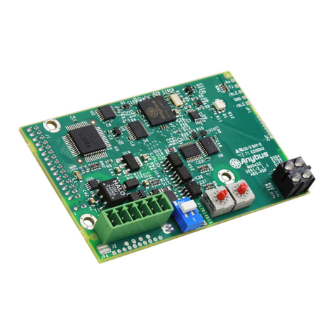
SONIX MP5S Plus Writer User manual

MP5S Writer
快速指引手册
SONIX TECHNOLOGY CO., LTD. Page 1 Version 06
Preface
Thank you very much for choosing MP5S Plus Writer. We will try our best to design excellent development
tools and provide perfect after-sales service for you.
The manual is designed to help you to get familiar with features of the Writer as soon as possible, from which
you can learn operation, fault treatment method and other information of the Writer. For better use of it, please
read the manual carefully before using the writer.
The contents of the manual strive to be comprehensive and correct, but there are unavoidable omissions or
deficiencies, if you find any errors or ambiguities in the manual, please contact with us. However, the revision due
to product performance improvements or updates will not be informed in advance. You can pay attention to our
product update news on the company website, consult agents or contact with us directly
AMENDMENT HISTORY
Version
Date
Description
V01
2018.12.20
First version released
V05
2019.1.15
Modify some content
V06
2020.3.16
Add example analysis

MP5S Writer
快速指引手册
SONIX TECHNOLOGY CO., LTD. Page 2 Version 06
Contents
1
1
1
Product Introduction............................................................................................................................................ 3
1.1 Features ............................................................................................................................................... 3
1.2 Function Overview ...............................................................................................................................3
1.3 Standard Configuration ........................................................................................................................ 3
1.4 Product Appearance ............................................................................................................................ 4
2
2
2
Online Operation................................................................................................................................................. 5
2.1 Hardware Installation ........................................................................................................................... 5
2.1.1 Installation steps ........................................................................................................................... 5
2.1.2 Verify method of MP5S Connection..............................................................................................6
2.2 Software Operation .............................................................................................................................. 7
2.2.1 Software Installation .................................................................................................................... 7
2.2.2 Select IC and Download Writing Program ....................................................................................7
2.2.3 Writing Steps (Auto write, Blank Check, Write, Verify, Read)......................................................9
2.2.4 Language and Offline Mode Setting ...........................................................................................10
3
3
3
Offline Write......................................................................................................................................................12
3.1 Manual Write ......................................................................................................................................12
3.2 Write on Machine ...............................................................................................................................12
3.3 Offline Write Mode Description ..........................................................................................................13
3.4 Write Error Message Description.......................................................................................................13
4
4
4
Trouble shooting...............................................................................................................................................14
4.1 Test Mode ..........................................................................................................................................14
4.2 Common Online Failures and Countermeasures ..............................................................................15
4.3 Common Offline Failures and Countermeasures ..............................................................................16
5
5
5
IC Socket (Three sockets provide from Sonix for customer to purchase)........................................................17
5.1 Suit for SOP16,SOP14,SOP8............................................................................................................17
5.2 Suit for SSOP28,SSOP26,SSOP24 and less pins SSOP.................................................................17
5.3 Suit for LQFP48 .................................................................................................................................17
6
6
6
Example analysis..............................................................................................................................................18
6.1 MP5S write interface..........................................................................................................................18
6.2 Write Packege IC...............................................................................................................................19
6.2.1 Connection..................................................................................................................................19
6.2.2 Transfer Board............................................................................................................................19
6.3 Write Dice IC......................................................................................................................................20
6.4 Write SONIX COB..............................................................................................................................21
7
7
7
Warranty Description........................................................................................................................................22
Note: To quickly know the application of MP5S, please refer to chapter 6
“Example analysis”.

MP5S Writer
快速指引手册
SONIX TECHNOLOGY CO., LTD. Page 3 Version 06
1
1
1
Product Introduction
The MP5S Plus Writer supports writing SONiX SA2 Speech OTP IC, but is incompatible with the MP5 writer of
SONIX SA1 MCU temporarily, please use them separately. The supported OTP ICs include snc27p snc86p and
snc32p at present.
1.1 Features
Plug and play;
Support online and offline writing operations;
Removable-type transfer board;
Support downloading the writing file in the case of power supply only by USB;
Support analyzing MCU without downloading the writing file;
1.2 Function Overview
Auto-Write ( Blank Check + program);
Blank Check;
Program ;
Verify;
Read ROM;
Write on machine;
1.3 Standard Configuration
Figure 1-1 MP5S Writer and Accessories Schematic Diagram

MP5S Writer
快速指引手册
SONIX TECHNOLOGY CO., LTD. Page 4 Version 06
1.4 Product Appearance
Figure1-2 MP5S Plus Writer Appearance
LCD
For displaying the writing information, function indication and operation result;
LED
OK (green): Complete;
FAIL (red): Failure;
BUSY (yellow): Writing in process;
Key
Enter: Execute Key, for executing the writing or terminating the alert prompt;
Mode: Mode key, for selecting the operation mode (the mode key can be seen by opening the upper cover).

MP5S Writer
快速指引手册
SONIX TECHNOLOGY CO., LTD. Page 5 Version 06
2
2
2
Online Operation
2.1 Hardware Installation
2.1.1 Installation steps
Insert the transfer board corresponding to the IC to be written into the MP5S, as shown in Figure 2-1.
Figure 2-1
Put the IC into the IC adapter, make pins of the IC correspond to metal pins on the board one by one, as
shown in Figure2-2; (The adapter can be bought from the internet or from Sonix)
Figure 2-2
Insert the adapter into the MP5S, and then connect, as shown in Figure 2-3
Figure 2-3
Note: Place the IC writing seat as shown in the above figure, pin1 of IC is at the upper left, and the pins of IC align
to the pins on the bottom of the MP5S seat.

MP5S Writer
快速指引手册
SONIX TECHNOLOGY CO., LTD. Page 6 Version 06
2.1.2 Verify method of MP5S Connection
Sometimes, when writing, the error information is given from PC, show the IC isn’t place correct, then you can
Verify the connection as below
Draw out the power line and USB line from MP5S,and open the MP5S
Note: Every transfer board ,the writing pins of M5S are fixed,on J2.
Check the connection of writing pins on J2 with corresponding pins on IC with multi-meter. If they short ,then
the connection is OK; Otherwise find the reason and solve it. Please refer our IC specs to know the pins of IC
IC
Transfer Board
IC pins
J2 VDD
All VDD pins,include VDD,VDDPWM and VDDIO
J2 GND
All GND pins
J2 CLK
CLK
J2 DATA
DATA
J2 MODE
MODE
J2 VPP
VPP
J2 TRIM
TRIM
Note: SNC32P &SNC86P have no this pin, and you needn’t to check it
In addition, if there have R1 resistor on transfer board, please check this resister connected OK or not. The
transfer boards of SNC27P have this resistor and SNC32P&SNC86P have no.

MP5S Writer
快速指引手册
SONIX TECHNOLOGY CO., LTD. Page 7 Version 06
2.2 Software Operation
2.2.1 Software Installation :
First, the customer shall download installation files of the MP5S Writer from official web site of Sonix
http://www.sonix.com.tw/article-tw-3257-32610
Use Micro USB wire to connect the MP5S Writer with PC;
Execute MP5SWriterVxxx.exe
Figure 2-4 MP5S Writer Interface
Note:
If USB link is OK, the sign on right down corner of software interface will turn from orange to green;
If USB link fail, then the color remain orange, and please find the reason and solve it;
2.2.2 Select IC and Download Writing Program
: Click the button on the top left corner, to show the interface of Figure 2-5, and select the
corresponding IC series and the specific IC to be written.

MP5S Writer
快速指引手册
SONIX TECHNOLOGY CO., LTD. Page 8 Version 06
Figure 2-5 Select Series and Model of MCU
Notes:
Option “下载 Bin”: The option is default option, Figure 2-6 will be popped up after confirming the option, then
the Bin file to be downloaded into the writer is selected, the file is downloaded after confirming, and in
common situation, the default option is enough to use.
Option “不下载 Bin”: "Blank Check" or " Read”is required sometime without writing, at this time the option can
be selected.
Figure 2-6 (Select the writing file to be written)

MP5S Writer
快速指引手册
SONIX TECHNOLOGY CO., LTD. Page 9 Version 06
Figure 2-7 (Successfully download the writing file)
2.2.3 Writing Steps (Auto write, Blank Check, Write, Verify, Read)
:“Auto Program”includes two actions: “Blank Check”and “program”.
After IC is placed into the MP5S socket, and the BIN file is downloaded into the MP5S , this button shall be clicked,
so that the MP5S Writer will execute the above two actions in turn, if any of the three actions is error, the MP5S will
give the corresponding error message and stop . If the writing is successful, then the interface of Verify Success is
appeared, as shown in Figure 2-8;;
Figure 2-8 "Verify" Success Interface
“Blank check ", "program", "verify" and other actions may be executed separately.

MP5S Writer
快速指引手册
SONIX TECHNOLOGY CO., LTD. Page 10 Version 06
Check whether the IC is blank or not, and give the corresponding information;
Write the BIN file downloaded in the MP5S to IC; (in some cases, part of the BIN file has been
written in the IC, but the file is not complete, at this time the IC may be inserted into the MP5S again, and click
the button to continue writing until the Bin file is completely written. )
Check if the data written into the IC is correct; If not, the information will be given;
Read the value written in the IC; (Note: the read data is not original Bin file, but the customer can
compare the value of IC which is written successfully and the value of IC which is written failure, so that the ROM
region having writing error of the IC which is written failure can be found.)
View Writing Information
Include writing time, the number of successes, and the number of failures, is used for clearing information.
2.2.4 Language and Offline Mode Setting
Click “Option” on the top right corner of the software interface, to show the following interface as
Figure 2-9
Figure 2-9 (Language Setting)

MP5S Writer
快速指引手册
SONIX TECHNOLOGY CO., LTD. Page 11 Version 06
Figure 2-10 (settings for offline default mode)
FUN0: Include “Blank Check”+ “program”;
FUN6: Include “Program”, without blank check, so the time of offline writing is short than that of FUNO
mode.
Note: If the offline default mode is not set in the software interface, the writing mode of the MP5S in offline
mode will retain the previous setting, and in addition, the mode can be set by MODE key in offline mode.

MP5S Writer
快速指引手册
SONIX TECHNOLOGY CO., LTD. Page 12 Version 06
3
3
3
Offline Write
Download the program into the MP5S in online mode, select the offline mode in the software interface (or
select by the mode key in offline mode)
Fun0: In offline write, “Blank Check”+ “program”, the “Blank Check”will be executed at first, so the writing
time will be relatively longer.
Fun6: In offline write, “program”, the writer will directly write without black check, so the writing time will be
relatively shorter。
3.1 Manual Write
Remove the USB cable, disconnect from the computer, and supply power to the MP5S through the power
adapter, the writer will reset automatically and enter the offline mode. (The writer will automatically check whether
the Checksum value is correct, or it cannot start up and display "Err4"; If correct, the model of MCU to be written
and the software version of the writer will be displayed at first, the yellow LED will flash once and the buzzer will
ring once, and then the model of MCU to be written and the Checksum value are display in cycle, the checksum
value is same as the File checksum value of the software when it is connected with the computer.)
Manually press "Mode" key and "Enter" key to choose a function to be executed. At the same time, the writing
information can be viewed according to the LEDs.
"Mode": Mode selecting key, the key can be seen by opening the iron shell of MP5S, generally the mode is
selected in the software, and the key is not used in manual mode.
Enter": click the key to begin writing, then check whether the writing is success or failure through the LCD.
3.2 Write on Machine
Remove the USB cable, disconnect from the computer, and supply power to the MP5S through the power
adapter, place the MP5S on the writing machine, which is connected with the machine through 6 control lines.
Figure 3-1

MP5S Writer
快速指引手册
SONIX TECHNOLOGY CO., LTD. Page 13 Version 06
Pin
Name
Description
1
OK
MP5S output pin, output High level to machine after the writing is OK
2
BUSY
MP5S output pin, output High level to machine when it is being written.
3
FAIL
MP5S output pin, output High level to machine after the writing is failure.
4
ENTER
MP5S input pin, low trigger, MP5S starts writing after receiving low level sent by
the machine
5
3.5V
Power high
6
VSS
Power low
Note: there is a situation often reflected by customers that, the LED of MP5S is correct, but the machine put IC
in wrong tube, at this time, the six control lines should be checked, whether the high level value is normal, if normal,
please check the machine
3.3 Offline Write Mode Description
MODE
Function description
In execution
Success
Failure
Digital Tube
LED
Digital Tube
LED
Digital Tube
LED
Fun0
Blank + program
No display
Yellow
Checksum or
Rolling Code
Green
Err1 , Err2,
Err3 etc
Red
Fun1
Blank Check ( Erase )
No display
Yellow
Fun1
Green
Err1
Red
Fun2
Program
No display
Yellow
Checksum or
Rolling Code
Green
Err2,Err3
Red
Fun3
Verify
No display
Yellow
Checksum
Green
Err3
Red
Fun4
Read ROM
No display
Yellow
Checksum or
Rolling Code
-
Indeterminate
value
-
Fun5
Read Writer Files
No display
Yellow
Unencrypted
Checksum
-
Err4
Red
Fun6
Program + Verify
No display
Yellow
Checksum or
Rolling Code
Green
ERR2 , ERR3
Red
Fun7
Display Rolling Code value
No display
Yellow
Lowest Word
-
-
-
Fun8
Display MCU name and
version number
No display
Yellow
E.g: E7DC - E000
-
-
-
3.4 Write Error Message Description
Project
Error message
Description
1
ERR 0
Write voltage Error
2
ERR 1
Blank check test failure
3
ERR 2
Write failure
4
ERR 3
Verify failure
5
ERR 4
Read-write data error
6
ERR 5
CHIP ID Error
7
ERR 6
MCU’s pins have poor contact or are placed in the wrong direction

MP5S Writer
快速指引手册
SONIX TECHNOLOGY CO., LTD. Page 14 Version 06
4
4
4
Trouble shooting
4.1 Test Mode
In offline condition, the voltage of the MP5S writer can be measured in test mode. Steps to enter the test mode
are as follows:
Open the upper shell and remove the placed IC;
Hold on “Enter”key, power on the writer, and light the green, yellow and red led in cycle, and meanwhile the
buzzer beeps regularly, and the digital tube displays 0000-9999 in cycle, so that the test mode is entered, please
release the “Enter”key.
Measure VXX/VPP voltage by using calibrated multi-meter, and specific location is as shown in Figure 4-1.
Normal condition: VXX Voltage alternates between 3.3V and 5V; VPP Voltage alternates among 5V, 6.5V, 7.5V
and 12.7V;
It can preliminarily check whether hardware of MP5S is damaged by measuring the voltages of VXX and VPP of
the MP5S in the test mode.
After the measurement is completed, power on again, the MP5S will enter normal operation mode.

MP5S Writer
快速指引手册
SONIX TECHNOLOGY CO., LTD. Page 15 Version 06
4.2 Common Online Failures and Countermeasures
The MP5S Plus Writer prompts for different types of failures in online mode;
For different information, the countermeasures are shown in the following table:
No.
Type and information of failure
Countermeasure
1
Error: USB Device is Not detected!!!
A: Ensure the USB cable is well connected with the computer and the
writer;
B: Change to other USB interfaces of the computer;
C: Change the USB cable.
2
MCU Type and the writing file are inconsistent!!!
Please try again!!!
Please confirm the type of selected MCU and the writing file are
consistent, and then redownload the writing file;
3
Incorrect writing file!!!
A : Check the writing file or the setting of Rolling
Code!!!
B : Please redownload the writing file!!!
Please confirm whether the setting of Rolling Code in the source code
is consistent with the INI file;
4
VXX or VPP Error!!!
A : Check VXX and VPP of MP5S Writer!!!
B : Check MCU Placement Direction!!!
A: Please remove MCU , and power on again;
B: Remove MCU , if there is still the prompt, please contact with the
supplier or SONiX;
6
Cannot find MCU!!!
A: Please check Text tool!!!
b: Check MCU model and placement direction!!!
A: Please place MCU ;
B: MCU of other model is placed , please replace;
C: MCU placement or direction is incorrect;
D: There are open/short-circuit and other problems in some pins of the
placed MCU;
7
Please check MCU Model!!!
Place MCU of other model;
8
Blank check failure!!!
Please confirm the used MCU is blank;
9
A: Erase failure!!!
B: Return signal failure!!!
C: Write program failure!!!
D: Read ROM failure!!!
E: Read Flash failure!!!
F: IHRC Correction failure!!
G: Compare checksum failure!!!
A: Confirm that MCU is well contact with the MP5S Writer;
B: Confirm that the used cable is shorter than 15cm;
C: Confirm the used socket is in good contact, please clean and replace
regularly;
D: Whether the pins of MCU have open/short circuit;
If there is still problem, please contact with the supplier or SONiX;
10
Verify failure!!!
A: Confirm the writing file is consistent with the data of MCU to be
written;
B: Confirm that MCU is well contact with the MP5S Writer;
C: Confirm that the used cable is shorter than 15cm;
D: Confirm the used socket is in good contact, please clean and replace
regularly;
E: If there is still problem, please contact with the supplier or SONiX;

MP5S Writer
快速指引手册
SONIX TECHNOLOGY CO., LTD. Page 16 Version 06
4.3 Common Offline Failures and Countermeasures
The MP5S Writer prompts for different types of failures in offline mode;
For different information, the countermeasures are shown in the following table:
No.
Type and
information of
failure
Countermeasure
1
ERR0
A: Remove MCU and the transfer board, reset the writer, and then check whether the alarm is
on; if there are still alerts, please contact with the supplier or SONiX;
B: Please confirm whether VXX/VPP of the Writer is within the range;
C: Please confirm that the type of the transfer board is consistent with the MCU model;
2
ERR1
Please confirm the used MCU is blank;
3
ERR2
A: Confirm that MCU is well contact with the MP5S Writer;
B: Confirm that the used cable is shorter than 15cm;
C: Confirm the used socket is in good contact, please clean and replace regularly;
D: There are open/short-circuit and other problems in some pins of the placed MCU, please
replace;
4
ERR3
A: Confirm the writing file is consistent with the data of MCU to be written;
B: Confirm that MCU is well contact with the MP5S Writer;
C: Confirm that the used cable is shorter than 15cm;
D: Confirm the used socket is in good contact, please clean and replace regularly;
E: There are open/short-circuit and other problems in some pins of the placed MCU, please
replace;
5
ERR4
The data stored in the writer is abnormal, please redownload the writing file;
6
ERR5
MCU of other model is placed, please place the correct MCU;
7
ERR6
A: Please place MCU;
B: MCU of other model is placed, please replace;
C: MCU placement or direction is incorrect;
D: There are open/short-circuit and other problems in some pins of the placed MCU.

MP5S Writer
快速指引手册
SONIX TECHNOLOGY CO., LTD. Page 17 Version 06
5
5
5
IC Socket (Three sockets provide from Sonix for customer to purchase)
5.1 Suit for SOP16,SOP14,SOP8
Put IC into socket,pin1 of IC is at the upper left, and the pins of IC align to the pins on the bottom of socket.
SONIX Part Number
FPD-SKS16-A0
parameter:SOP16/1.27mm/150mil
5.2 Suit for SSOP28,SSOP26,SSOP24 and less pins SSOP
Put IC into socket,pin1 of IC is at the upper left, and the pins of IC align to the pins on the bottom of socket.
SONIX Part Number
FPD-SKTX28-A0
parameter:SSOP28/0.65mm
5.3 Suit for LQFP48
SONIX Part Number
FPD-SKF48-A0
parameter:LQFP48/0.5mm

MP5S Writer
快速指引手册
SONIX TECHNOLOGY CO., LTD. Page 18 Version 06
6
6
6
Example analysis
6.1 MP5S writer interface
J1: Correspond to SOCKET’s pin one by one, when IC inserts into SOCKET, J1 corresponds to the pins of the IC
one by one;
J2: Connect with the master writing line on the motherboard, J2 has fixed position.
Writer Pins
Explain
Note
VDD
Power for IC VDD
Must connect (connect all the IC’S VDD pin)
GND
Power for IC GND
Must connect (connect all the IC’s GND pin)
VPP
Power for Write operation
Must connect
MODE
Write mode
Must connect
CLK
Write CLK
Must connect
DATA
Write Data
Must connect
TRIM
Trim IC’s frequency
Some IC have no this Pin, and some IC have, please refer
to the SPEC of IC。

MP5S Writer
快速指引手册
SONIX TECHNOLOGY CO., LTD. Page 19 Version 06
6.2 Write Package IC
6.2.1 Connection
6.2.2 Transfer Board
The transfer board is used to connect IC’s pins to Writer’s pins
Note: On SNC27P IC transfer board,there have a 620R resister between Data pin and GND pin.
Different IC corresponds to different transfer board, and you can select the transfer board from the software’s
interface as below.
Table of contents
Popular Network Hardware manuals by other brands
Enterasys
Enterasys ER16-SERC-04-AA quick start
Paradyne
Paradyne FrameSaver SLV 9124 Technical reference
MTL
MTL 9468-ET instruction manual
Paradyne
Paradyne ACCULINK 3151 CSU Quick reference guide
Agilent Technologies
Agilent Technologies E5071C ENA Series Service note
Lab.gruppen
Lab.gruppen NLB 60E Operation manual
Equinox Systems
Equinox Systems Equinox Console Manager CCM4850 CCM4850... Installer/user guide
SET
SET cRIO LVDT 9312 Technical description
ADTRAN
ADTRAN TSU ACE Installation information

Paradyne
Paradyne 7110 Benefits
SCK Direct, Inc.
SCK Direct, Inc. SmartDirect 2 installation guide
Cradlepoint
Cradlepoint COR IBR900 Series quick start guide

