Sharkoon WPC Bronze Series User manual

Manual

TABLE OF CONTENTS
1. General 3
2. Specifications 3
2.1 Overview 3
2.2 Mains Voltage and Protections 4
2.3 Safety Certifications 5
3. Package Contents 5
4. Cable Configuration 5
4.1 Connection Options 5
4.2 Cable Diagram WPC450/550 6
4.3 Cable Diagram WPC650/750 6
5. Installation 6
5.1 Installing the Power Supply into a PC Case 6
5.2 Connecting Mainboard and Graphics Card(s) 7
5.3 Connecting Optical Drives and Other Peripheral Devices 7
5.4 Checking All Connections 7
6. Troubleshooting 8

WPC
3
Dear Customer,
Thank you for your purchase of this high-quality SHARKOON product. To ensure a long service life, and full
functionality of the product, we recommend that you read this manual thoroughly.
SHARKOON Technologies
www.sharkoon.com
1. General
Power 450, 550, 650 or 750 Watt
CPU Compatible with the latest Intel and AMD CPUs
Warranty 3 Years
PCIe Connectors WPC450/550 Bronze: 2x 6+2-Pin PCIe Connectors
WPC650/750 Bronze: 4x 6+2-Pin PCIe Connectors
80 PLUS Certification Bronze
Fan 120 mm Fan
Efficiency
20% Load: Min. 82%
50% Load: Min. 85%
100% Load: Min. 82%
2. Specification
2.1 Overview
Model No. WPC450 Bronze
Input (AC) Input Voltage Current Frequency
115 - 230 VAC 8 A 50 - 60 Hz
Output (DC) +3.3 V +5 V +12 V -12 V +5 Vsb
Max. Output Current 20 A 20 A 33.75 A 0.3 A 2.5 A
Max. Combined Power 103 W 405 W 3.6 W 12.5 W
Total Power 450 Watt

WPC
4
Model No. WPC550 Bronze
Input (AC) Input Voltage Current Frequency
115 - 230 VAC 8 A 50 - 60 Hz
Output (DC) +3.3 V +5 V +12 V -12 V +5 Vsb
Max. Output Current 22 A 22 A 41.25 A 0.3 A 2.5 A
Max. Combined Power 120 W 495 W 3.6 W 12.5 W
Total Power 550 Watt
Model No. WPC650 Bronze
Input (AC) Input Voltage Current Frequency
115 - 230 VAC 10 A 50 - 60 Hz
Output (DC) +3.3 V +5 V +12 V -12 V +5 Vsb
Max. Output Current 22 A 22 A 48.75 A 0.3 A 2.5 A
Max. Combined Power 120 W 585 W 3.6 W 12.5 W
Total Power 650 Watt
Model No. WPC750 Bronze
Input (AC) Input Voltage Current Frequency
115 - 230 VAC 10 A 50 - 60 Hz
Output (DC) +3.3 V +5 V +12 V -12 V +5 Vsb
Max. Output Current 22 A 22 A 56.25 A 0.3 A 2.5 A
Max. Combined Power 130 W 675 W 3.6 W 12.5 W
Total Power 750 Watt
2.2 Mains Voltage and Protections
The WPC works with 115 - 230 Volts. It is available with the following protective measures:
1. Over Power Protection (OPP)
If a voltage rail draws in more electricity to the power supply than the specifications allow, the power supply
will switch off.
2. Over Voltage Protection (OVP)
This function protects against excessive voltage, preventing damage to the PC by switching off the power
supply during a surge.
3. Under Voltage Protection (UVP)
If the power supply falls below a fixed number of the minimum voltage, the power supply will switch off
automatically.
4. Short Circuit Protection (SCP)
Should a short circuit occur with your PC, the SCP function switches off the power supply and protects the
electronics from damage.

WPC
5
2.3 Safety Certifications
Our power supply is tested and complies with CE, FCC and CB safety certifications.
3. Package Contents
Note:
If you are missing any of the items listed above, please contact our customer service immediately:
support@sharkoon.com (Europe)
support@sharkoon.com.tw (International)
4. Cable Configurations
4.1 Connection Options
WPC Bronze
Power cord
Mounting screws
Cable ties
Manual
C
C
B
B
A
A
D
D
E
E
1x 20+4-Pin Mainboard Connector 1x 4+4-Pin CPU Connector WPC450/550 Bronze:
2x 6+2-Pin PCIe Connector
WPC650/750 Bronze:
4x 6+2-Pin PCIe Connector
WPC450/550 Bronze:
5x SATA Connector
WPC650/750 Bronze:
6x SATA Connector
2x IDE Connector 1x Floppy Connector

550 mm
550 mm
550 mm
550 mm
550 mm
550 mm
150 mm
150 mm
150 mm
150 mm
150 mm
150 mm
150 mm
150 mm
150 mm
150 mm
150 mm
150 mm
150 mm
150 mm
550 mm
550 mm
550 mm
550 mm
550 mm
550 mm
550 mm
WPC
6
4.2 Cable Diagram WPC450/550
5. Installation
If installing into an empty PC case, please continue to section 5.1. If a power supply is already installed,
remove it first from the case.
To do so, proceed as follows:
1. Turn off your PC. Disconnect the power cord from the wall outlet and your power supply.
2. Open the PC case. For additional information, refer to the manual of the PC case.
3. Disconnect all cables between the power supply and the other PC components (e.g. mainboard, HDDs,
drives, fans, etc.).
4. Remove the mounting screws connecting the power supply to the PC case and then carefully remove the
power supply from the case.
5.1 Installing a Power Supply into a PC Case
1. Insert the power supply into the PC case and place it against the power supply bracket on the rear panel. For
additional information, refer to the manual of the PC case.
2. Attach the power supply from the outside of the case using the provided screws. Ensure that the fan and air
vents of the built-in power supply are not covered.
1x 20+4-Pin
Mainboard Connector
1x 20+4-Pin
Mainboard-Connector
1x 4+4-Pin
CPU Connector
1x 4+4-Pin
CPU Connector
2x 6+2-Pin
PCIe Connectors
4x 6+2-Pin
PCIe Connectors
5x SATA Connectors
6x SATA Connectors
2x IDE Connectors 2x IDE Connectors
1x Floppy Connector 1x Floppy Connector
4.3 Cable Diagram WPC650/750

WPC
7
5.2 Connecting Mainboard and Graphics Card(s)
1. Plug the 20+4-pin mainboard connector (Fig. 1) into the respective port of the mainboard.
2. If your mainboard also features either a 4-pin or 4+4-pin CPU connector, connect the plug with the
mainboard port (Fig. 2).
Note:
The power connection of the mainboard depends on the vendor and may vary. For detailed information on
how to establish the power connector, please refer to your mainboard’s manual.
3. If your PCIe graphics card requires an additional power supply, connected the 6-pin or 6+2-pin PCIe con-
nector to ensure the graphics card receives a stable power supply (Fig. 3).
5.3 Connecting Optical Drives and Other Peripheral Devices
Connect the IDE connector (Fig. 4), SATA connector (Fig. 5) and the Floppy connector (Fig. 6) with the appro-
priate peripherals.
Note:
For additional information, refer to the respective manuals of your drives and peripheral devices.
5.4 Checking All Connections
Ensure that all devices are properly connected. Close the PC case. Connect the power
cord with the power supply and wall outlet. Turn the power supply on. This completes
the installation of the power supply.
Note:
All connectors are designed to avoid misconnection. If the connectors are unable to connect to the main-
board, drives or peripheral devices, please check if both connectors are attached in the correct orientation.
Do not force to plug the connectors within the incorrect orientation, nor modify any of the components, as
this will damage the power supply and other hardware. SHARKOON warranty does not cover damage cause
by incorrect handling.
Fig. 1: 20+4-Pin Mainboard Connector Fig. 2: 4+4-Pin CPU Connector Fig. 3: 6+2-Pin PCIe Connector
Fig. 4: IDE Connector Fig. 5: SATA Connector Fig. 6: Floppy Connector
On/Off Switch for
the Power Supply

WPC
8
6. Troubleshooting
If the power supply does not work properly, please check the following:
1. Is the power cord correctly inserted into a wall outlet and the power inlet of the power supply?
2. Ensure that the on/off switch is in the “I” position.
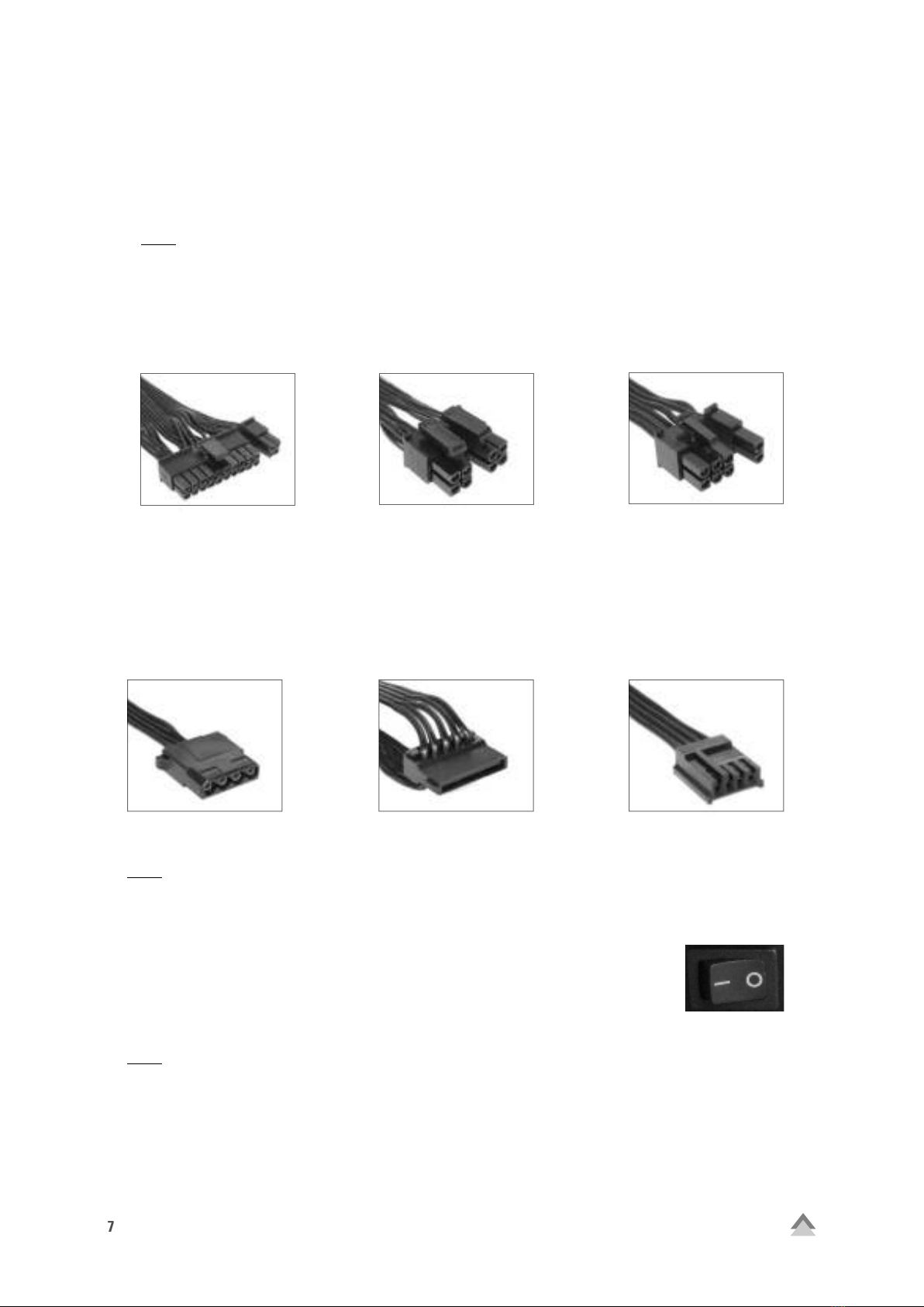
3. Check if the 20+4-pin mainboard connector and the 4+4-pin CPU connector are correctly
attached to the mainboard.
4. Check if the cable is securely connected to the port of the peripheral devices.
5. Unplug the power cord from the wall outlet and let the power supply rest for about 10 minutes. This will
trigger a reset of the protection circuitry.
If the system still does not start, please contact support@sharkoon.com.
Legal Disclaimer:
For potential loss of data, especially due to inappropriate handling, SHARKOON assumes no liability. All na-
med products and descriptions are trademarks and/or registered trademarks of the respective manufacturers
and are accepted as protected. As a continuing policy of product improvement at SHARKOON, the design
and specifications are subject to change without prior notice. National product specifications may vary. The
legal rights of the enclosed software belong to the respective owner. Please observe the license terms of
the manufacturer before using the software. All rights reserved especially (also in extracts) for translation,
reprinting, reproduction by copying or other technical means. Infringements will lead to compensation. All
rights reserved especially in case of assignation of patent or utility patent. Means of delivery and technical
modifications reserved.
Disposal of your old product:
Your product is designed and manufactured with high quality materials and components, which can be recy-
cled and reused.
When this crossed-out wheeled bin symbol is attached to a product, it means the product is covered
by the European Directive 2012/19/EU.
Please be informed about the local separate collection system for electrical and electronic products. Please
act according to your local rules and do not dispose of your old products with your normal household waste.
The correct disposal of your old product will help prevent potential negative consequences to the environment
and human health.
SHARKOON Technologies GmbH
Siemensstraße 38
35440 Linden
Germany
© SHARKOON Technologies 2017
info@sharkoon.com
www.sharkoon.com
This manual suits for next models
4
Table of contents
Other Sharkoon Power Supply manuals

Sharkoon
Sharkoon DRIVELINK COMBO USB3.0 User manual

Sharkoon
Sharkoon REBEL P30 Gold User manual

Sharkoon
Sharkoon SHP550 User manual

Sharkoon
Sharkoon SHP BRONZE User manual

Sharkoon
Sharkoon QP500 User manual

Sharkoon
Sharkoon WPM Bronze 400 User manual

Sharkoon
Sharkoon Silent Storm SHA460-135A User manual

Sharkoon
Sharkoon SilentStorm Icewind 550 User manual

Sharkoon
Sharkoon SHP650 User manual

Sharkoon
Sharkoon SilentStorm SFX Gold Series User manual