Sonniger Heater R1 User manual

Technical Documentation water fan HEATER T&S
OPERATION AND MAINTENANCE DOCUMENTATION
Commercial Industrial Heat Limited
Unit 1A Burnfoot Industrial Estate
Hawick, TD9 8SL
Tel: +44 (0) 1450 372103, Fax: +44 (0) 1450 377800
Website: www.turnbull-scott.co.uk
Email: Info@turnbull-scott.co.uk

Technical Documentation water fan HEATER T&S
1. INTRODUCTION
HEATER heating and ventilation devices are designed to be applied in the buildings of small and medium capacity,
especially such as: production and warehouse halls, car showrooms and service stations, sports halls and stadiums, sacral
buildings and churches, retail stores and wholesales outlets, agricultural facilities, exhibition surfaces.
2. DIMENSION AND BASIC TECHNICAL PARAMETERS
Basic elements of HEATER devices:
Casing made of highly resistant EPP (expended polypropylene) material
Regulated air–conduits
Installation bracket
3 step axial fan 450 mm dimension; fan is protected from direct access to revolving elements with safety netting
Heat exchanger –(Cu/AL) made of copper tubes placed in an aluminum lamellar exchanger /block with stub
connection ½’, ¾”.Stub connections are equipped with air-release valves and heat outlet vent.
*for temperatures of 90/70 and inlet temperature of O˚C
**maximum height of assembly for vertical airflow, max working range of up to 380m². Horizontal range of isothermal stream at
velocity boundary/speed limit of 0.5 m/s
***measurement obtained when 5 m away from the device

Technical Documentation water fan HEATER T&S
3. GENERAL INFORMATION
HEATER heating and ventilation devices are manufactured in compliance with standards concerning quality, ecology, utility and
work comfort.
HEATER devices are delivered ready-to-use in a cardboard package that is to protect from mechanical damages. The package
consists of: the device, the Manual (Operation and Maintenance Documentation) and Guarantee. If the optional automatic
control ordered, it shall be delivered in a separate package. Make sure all the aforementioned elements are in the package
immediately after the delivery. In the absence of any element, please fill in the suitable carrier document.
4. ASSEMBLY
Prior to any installation procedures, take the following aspects into consideration: easy access for maintenance works, access to
water and electrical installation, appropriate air distribution in a room.
Every HEATER unit is equipped with a set of 3 interchangeable color inserts; in order to change the color, remove the insert
from the front panel and place the desired one back in place.
*It is advisable to mount the device to the wall or the ceiling on original mounting brackets, supporting mount pins (not delivered
with the device) or supporting constructions (shapes and dimensions of the supporting construction may be individually
designed in compliance with durability and strength requirements).
In case of mounting to the ceiling, pay attention to the fact that air-release/venting of the device may be difficult so it is advisable
to place vent at the highest point of the pipework.
The device may be mounted to the wall with the use of a mounting bracket at the angle of 0°, 30° or 60 °. A mounting bracket
holder is made of curved profile. It has two holes for vertical assembly. Assembly to the wall and/or to the ceiling is possible at
different angles but it requires making necessary holes in the holder.
ATTENTION !
Przed Before mounting read the manual carefully and adhere to the rules concerning the mounting procedures. Not
applying may result in inappropriate functioning of the device and the loss of the guarantee rights.
Pay special attention when working with electrical elements of the device.
Any installation operations must be carried out by qualified persons with appropriate authorizations

Technical Documentation water fan HEATER T&S
HTG-0001_0 7_z e_s zpilkami
W
AGA:
A
2
A
RKUSZ 1 Z 1
S
KALA:1:10
N
R RYSUNKU
T
YTUŁ:
P
OPRAWKA
N
IE SKALUJ RYSUNKU
M
ATERIAŁ:
D
ATA
P
ODPIS
I
MIĘI NAZWISKO
S
TĘP OSTRE
K
RAWĘDZIE
W
YKOŃCZENIE:
C
HYBA ŻE OKREŚLONO INACZEJ:
W
YMIARY SĄW MILIMETRACH
W
YKOŃCZENIE POWIERZCHNI:
T
OLERANCJE:
L
INIOWA:
K
ĄTOWA:
Z
.JAKOŚCI
W
YPROD.
Z
ATWIER.
S
PRAWDZ.
N
ARYS.
3. INSTALACJA ELEKTRYCZNA
NOTICE !
To sustain proper functioning of the device keep a safe distance–200mm from its sides and 300 mm from its
backside (from the fan)
Mounting bracket to the heater
The bracket set consists of: a holder, two
sleeves, two M8 screws and washers. In
order to mount the bracket, drill two Ø12-
13mm holes in places visibly marked on
the casing. Insert sleeves into drilled
holes and place the bracket in. The
included holder must be screwed with M8
screws with washers.
Installation of mounting pins
To mount the heater to the ceiling, use
M8 mounting pins. Drill two Ø8-9mm
holes in places visibly marked on the
casing. Mounting pins may be screwed
into the frame not deeper than 20 mm.
.
Assembly of HEATERMIX air mixer
To mount HEATERMIX air mixer to the
ceiling, use M8 mounting pins. Drill two
Ø8-9mm holes in places visibly marked
on the casing. Mounting pins may be
screwed into the frame of a heat
exchanger to the maximum depth of
20mm. Mounting pins and connecting
elements are not included with the unit.

Technical Documentation water fan HEATER T&S
5. ELECTRICAL INSTALLATION
The electrical installation and connection to power supply must be done in compliance with the existing regulations and
standards for building industry.
The fan’s engine is equipped with the internal temperature limit fuse protecting the engine from its overheating.
The unit set does not consist of: a feeding cable, a master switch (see diagram)
The electrical installation must be done by an authorized person, acquainted with the Manual. The connection of the feeding
cable and master switch must be done in compliance with electrical diagram (with or without the automatic control, depending
on the option chosen). Any and all damages incurred as a result of the aforementioned causes are not provided with the
Guarantee and the user will be charged with any costs of the device exchange. The connection of the automatic control should
be carried out in accordance with the electrical diagram.
In case of any doubts or problems, unplug the device and contact the device’s installer or SONNIGER Authorized Service.
6. WATER INSTALLATION
The installation of the unit should be done in a way enabling maintenance service; on both stub pipes manual closing valves
should be installed in order to cut off the device. Feeding cables of the heater shall be connected in accordance with the
symbols/marking on the casing (inlet/outlet). In case of electromagnetic valve (with the option of the automatic control) it should
be installed on the outlet as it may be damaged otherwise. When the pipework is being connected to the exchanger, secure the
connections of the heater from oscillating torque (see figure) that may cause leakage in the exchanger.
OUT G 3/4"
IN G 3/4"
WATER DRAIN
AIR VENT
7. AUTOMATIC CONTROL –INSTALLATION
A set of automatic control may be used (powered 230V) that consists of the following:
COMFORT panel –including room thermostat and switch for regulation of 3 speeds of fan. One
COMFORT panel may regulate up to 3 pcs of HEATER units
2-way water valve with actuator; valve should be installed on a return stub of the heater
INTELLIGENT electronic control panel with an automatic speed controller, weekly program and BMS
communication. One INTELLIGENT panel may regulate up to 2 pcs of HEATER units
Splitter MULTI 6 - control up to 6 pcs of HEATER units from one COMFORT or INTELLIGENT Panel
The system is ready to start once the connections between the thermostat and the valve actuator are done, 230V power is
supplied to the thermostat and the fan’s motor is powered by the revs controller.
Heating medium
The connector pipes are at the back of the
device. When connecting the hydraulic
pipes/connections, make sure you secure the
connector pipes against rotational torque.
Notice that the connector pipes are not
strained by the pipes. The valve of heating
medium is on the supply pipe and the vent is
on the return pipe.
Use flexible connections to allow the heater to
be turned to the sides. Depending on the
flexible connections, the maximum turn is 78°
to both sides. Figure shows maximum angle to
one side and 50° to the other with minimal
distance left for connections.

Technical Documentation water fan HEATER T&S
8. FIRST START
Do all the connections (electrical, water and automatic control), check for tightness of all connections done by an installer and
air-release/vent the device then start the device in the following sequence:
1. Switch on the mains,
2. Set requested speed of fan on revs controller,
3. Set requested temperature on thermostat,
The fan operates continuously irrespective of whether the heater’s valve is opened or not.
9. TURNING OFF
To switch the device off do the following:
1. Set minimum temperature on thermostat –after 7 seconds valve will be closed and heating switched off.
2. Set main switch to the “0” position (off); fan will be switched off and the thermostat will be off the power.
10. OPERATION
The engine and fan used in HEATER units are maintenance-free devices but regular check-ups are advised, especially motor
and bearing (fan’s rotor should rotate freely, free from any axial and radial throws and undesired knocks/rattles).
11. MAINTENANCE
The heat exchanger requires systematical cleaning all dirt’s /impurities off. Before the start of the heating period the heat
exchanger is advised to be cleaned with compressed air directed to the air outlets; there is no need for dismantling of the
device. Pay special attention when cleaning the exchanger’s fin due to high possibility of damaging them. If fins are bent use a
tool specifically designated to carry out such repairs. If the device has not been used for a longer period of time, unplug it before
the next use.
The heat exchanger is not equipped with any fire protection device. The heat exchanger may be damaged if the room
temperature goes below 0 C.
Anti-freeze liquid must be added to the water circulation/system. Anti-freeze liquid must be appropriate for the material the
exchanger is made of (copper) as well as other elements of the hydraulic system/circulation. The liquid must be diluted with
water according to the solution recommended by the anti-freeze manufacturer.
NOTICE !
In case of any metallic knocks, vibration or increase in sound level check if the fan mounting/fixing does not work loose
contact the installer or SONNIGER Authorized Service
COMFORT panel description
ON/OFF –turning ON/OFF a unit
I-II-III –switch for fan speed regulation
HEAT - thermostat sends signal for valve and actuator and fan, fan turns off when temperature in room is
achieved, valve/actuator closes water supply.
FAN –function not active, unit will not operate when FAN switch is selected
COOL –thermostat sends signal only to fan, fan begins operation starting from temperature which is set on
thermostat (function used to air mixer HEATER MIX or for room ventilation in summer season)

Technical Documentation water fan HEATER T&S
12. TECHNICAL PARAMETERS HEATER

Technical Documentation water fan HEATER T&S
13. ELECTRICAL CONNECTION DIAGRAMS
1. Connecting HEATER with no automatic control
*The unit set does not consist of: a master switch, a fuse, a feeding cable
2. Connecting a few HEATER units with COMFORT panel, valves and actuators.
*The unit set does not consist of: a master switch, a fuse, a feeding cable
*One COMFORT panel may regulate up to 3 pcs of HEATER units
HEAT - thermostat sends signal for valve/actuator and fan, fan turns off when temperature in room is achieved,
valve/actuator closes water supply.
FAN –function not active, unit will not operate when FAN switch is selected
COOL –thermostat sends signal only to fan, fan begins operation starting from temperature which is set on thermostat
(function used to air mixer HEATER MIX or for room ventilation in summer season)
Attention! You can use additional jumper on the contacts 4-5 of COMFORT Panel, in this case you may only use function of
changing speed of fan I-II-III and ON / OFF. The thermostat and switches HEAT / FAN / COOL remain not active.
Additional jumper on terminals 4-5 might be applied when for ex different (supplied by user) thermostat is used to control the
system.
Fan wiring description
U1 high speed –brown
U2 middle speed –grey
U3 low speed –red
N neutral –black
PE protection - yellow/green

Technical Documentation water fan HEATER T&S
3. Connecting HEATER units with INTELLIGENT panel.
Intelligent PSH panel controls actuators/valves and automatically regulates fans’ speed depending on the required room
temperature. Fans speed changes automatically for lower rate, when temperature in a room gets closer to desired one.
Additional functions –weekly thermostat, availability of BMS communication signals
*One INTELLIGENT panel may regulate up to 2 pcs of HEATER units
*The unit set does not consist of: a master switch, a fuse, a feeding cable
4. Splitter MULTI 6 - control up to 6 pieces of HEATERs from one COMFORT or INTELLIGENT Panel
MULTI 6 Splitter allows connecting and controlling more fan heaters (up to 6 pcs.) and valves with actuators (up to 6 pcs.). Control of
fans and valves is done using COMFORT or INTELLIGENT panel.
To connect more than 6 fans and valves, it is possible to connect Splitter MULTI 6 with each other (maximum extension of up to 10
MULTI 6 splitters). In such case, in the first Splitter MULTI 6 there should be connector DS-N left open, in other Splitters MULTI 6
(2..10) connector DS-N must be closed.

Technical Documentation water fan HEATER T&S
5. Connection of HEATER unit with transformer speed regulator.
* When using transformer speed regulator please use only maximum speed connector on a fan - U1 high speed

Technical Documentation water fan HEATER T&S
14. INTELLIGENT automatic control –PROGRAMMABLE LOGIC CONTROLLER MANUAL
The control panel that is equipped with a weekly programmer selects speed of a device automatically depending on required/set
temperature. The lower the room temperature is, the higher the air output is. Any change of fan speed is automatic, without
user’s manual intervention.
Symbol
Meaning of the symbol
Switching ON/OFF
Program selection Auto/Cool/Heat, Menu button, programming button
Selection of fan operating mode, selection of days and times
Increase
Decrease
Screen lock
Heating
Cooling
Fan speed: low, medium, high
Automatic fan speed control
Number of a selected program
To switch on the heater, press . If the programmable controller is off, the OFF symbol will be displayed. When a controller is
off, press and hold the button for 3 seconds and the configuration will start. Press to select menu functions.
Menu
No
Description
Meaning/explanation
Regulation
01
Sensitivity
adjustment of
controller
Menu No.
The mount of degrees Celsius which changes fan speed. The standard
threshold level is set 1°C which means that the thermostat activates
heating if the outside temperature is less than 0.5°C than the required/set
temperature and switches heating off if the outside temperature is more
than 0.5°C than the required/set temperature. When the minimum
threshold level is 2°C, thermostat activates heating if the outside
temperature is less than 1°C than the required/set temperature and
switches heating off if the outside temperature is more than 1°C than the
required/set temperature.
Factory settings:
1°C, Regulation
ranges from 1°C to
10°C
02
Temperature
calibration
Menu No.
Menu allows you to calibrate displayed room temperature
- 1°C = temperature
reduction by 1°C
0°C = temperature
unchanged
1°C = increase by
1°C
03
Temperature
format
Menu No.
Menu allows you to select °C or °F
°C = °C
°F = °F
04
Clock format
Menu No.
Menu allows you to select 12-hour or 24-hour clock
Factory settings:
24H, options: 24H
lub 12H
05
Fan operation
modes
Menu No.
Operation options –fan may run continuously or only when
heating/cooling system is on
1 = fan working when
heating system is on
(factory settings)
0 = fan runs
continuously
Error warning
If any errors have occurred, one of the following messages will be displayed:
LO –room temperature is below 0°C, HI –room temperature is higher than 50°C, ERR –electrical shorts or controller is
damaged

Technical Documentation water fan HEATER T&S
Controller programming; Controller is factory pre-programmed as follows:
Hours
Programme
Heating (Mon. –Fri.)
Cooling (Mon. –Fri)
Heating (Sat. –Sun.)
Cooling (Sat. –Sun.)
Alarm
(07:00)
22°C
24°C
22°C
24°C
Out
(09:30)
16°C
28°C
16°C
28°C
Back (16:30)
22°C
24°C
22°C
24°C
Night (22:30)
16°C
25°C
16°C
25°C
Setting mode of operation:
Step 1
Press to select Heating mode, press and hold for 5 seconds to choose programs for days Monday - Friday
Step 2
When flashing icon of program 1 is displayed, you can change Hours of program 1. Press or to set time
(07:00 –factory settings). Press or to change time to the nearest 15 minutes.
Step 3
Press and use or to set required temperature for program 1 (22 ° C –factory settings)
Step 4
Press to change settings of program 2. Press or to set hours (09:30 –factory settings).
Step 5
Press and use or to set required temperature for program 2 (16 ° C –factor settings)
Step 6
Press to change settings of program 3. Press or to set hours
(16:30 –factory settings).
Step 7
Press use or to set required temperature for program 3 (22 ° C –factory settings)
Step 8
Press to change settings for program 4. Press or to set hours (22:30 –factory settings).
Step 9
Press and use or to set required temperature for program 4 (16 ° C –factory settings)
Step 10
Press to change weekend settings. Repeat steps from 2 to 9 and press to confirm.
NOTICE
Press to select cooling mode and repeat all of the above steps to program cooling mode.
To deactivate program 2 and 3 for weekends, press in step 4 (not ) –which deactivates time settings for weekends
and press in step 6 (not –which deactivates time settings for weekends. To reset changes, press again.
Time settings: the controller is equipped with a clock, which is important to be set right. To set time, press and hold till
displayed time is flashing. By pressing and set the right time. Press and hold till displayed day of the week is
flashing. By pressing and set the right day of the week. Press to confirm.
Resetting device to default settings: In stand-by mode, with the controller off press those buttons and hold them
for 5seconds till „RES” symbol is displayed (display time – 5 seconds).
Button lock: Press those buttons and hold them for 3 seconds to lock the device (repeat to unlock the device)
Fan speed setting: Press to select Low , Medium or High speed. In Auto mode the controller adjusts fan
speed on the basis of the following settings:
oHeating: 1° C below –LOW, 2° C below –Medium, 3° C below –High
oCooling: 1° C above –LOW, 2° C above –Medium, 3° C above –High
Heating/Cooling/Auto mode: Press to select Heating, Cooling or Auto mode.
Heating: the controller controls a system of heaters. Cooling: the controller controls a system of fans. Auto: the controller
controls a system of heaters or fans depending on the outside temperature.

Technical Documentation water fan HEATER T&S
GUARANTEE TERMS AND CONDITIONS
1. General
(a) In these Conditions of Sale:-
“The seller means Commercial Industrial Heat Ltd, “the buyer means a buyer of any goods from the seller and “the
goods means any goods sold by the seller to the buyer.
(b) The seller only does business upon the terms of these Conditions of Sale which shall be deemed to be
incorporated into any contract between the buyer and the seller. If there is any conflict between these conditions and
the terms of the buyer’s orders, these conditions shall prevail except to the extent that the seller has agreed in writing
that they are excluded. These Conditions of Sale shall not be altered or varied except by express written amendment
signed on behalf of the seller. The buyer confirms to the seller that no written or oral representation made by or on
behalf of the seller (other than as expressly incorporated in these Conditions of Sale) have induced the buyer to enter
into this contract.
2. Delivery
(a) Except where otherwise specifically stated in writing, any references to delivery shall be construed as
referring to date of dispatch from the seller’s works. Any period quoted will run from receipt by the seller of either the
buyer’s order or final technical information necessary for manufacture, whichever shall be the later.
(b) Quoted or acknowledged dates for dispatch are made by the seller in good faith and every effort will be made
to adhere to them but the seller shall not be under any liability whatsoever for the consequences of any delay. Time
for delivery is not of the essence of the contract.
(c) If for any reason the buyer fails to take delivery of any goods after it has received notification that they are
ready for delivery, the seller shall be entitled to invoice the buyer for any expense (including storage and insurance)
that may have been incurred as a result of the buyer’s failure to take delivery at the appropriate date.
(d) Delivery shall be deemed to have been accepted unless and to the extent that in the case of non-delivery the
seller is notified in writing within seven days from dispatch and in the case of damage, the goods are signed for as
damaged and the seller is notified on the day of delivery, such notification to be confirmed in writing within three days
after delivery.
(e) The seller reserves the right to deliver any goods by instalments and to invoice accordingly. The provisions
of these Conditions of Sale shall apply to such instalments as if each constituted a separate contract hereunder.
(f) Where goods are to be delivered by instalments and the buyer
(i) fails to accept any delivery when due; or
(ii) defaults making payment when due,
then in either case the seller may cancel any or all subsequent deliveries and the buyer shall compensate the
seller in full for any loss or expense arising from such cancellation.
(g) Delivery to the buyer is complete when the goods are unloaded from transport to the buyer or into the buyer’s
vehicle and the risk then passes to the buyer who shall be responsible for affecting his own insurance. The buyer
shall be responsible for the safe unloading of the goods from the vehicle in which they are delivered.
(h) If the seller replaces goods free or charge delivery shall be deemed to have been made and risk shall pass in
respect of those goods in accordance with condition 2 (g).
3. Warranty
(a) The seller warrants (subject to condition 6 below) that the goods manufactured by it are free from defects in
material or workmanship provided that the seller’s liability shall be limited to repair or replacement free of charge at
the seller’s works of the defective part within twelve months after delivery, provided notification of such failure or
defect is given to the seller immediately upon the same becoming apparent and on the seller’s request the goods are
promptly returned to the seller carriage paid.
(b) When the price quoted includes delivery other than at the seller’s works the seller will repair or, at its option,
replace free of charge, goods lost or damaged in transit, provided that it is given written notification of such loss or
damage within such time as will enable it to comply with the carrier’s conditions of carriage regarding loss or damage
in transit or where delivery is made by the seller’s own transport within a reasonable time after receipt of the advice
note.
(c) The seller warrants that it will have good title to sell all goods to be supplied and that they will be free from all
liens and encumbrances in favour of any third party not declared or known to the buyer before or at the time of
contract. In the case of goods supplied but not manufactured by the seller, the seller will, so far as it is able to do so,
extend to the buyer the benefit of the supplier’s warranty.
(d) The seller shall be under no liability for any defect which is due to accident, fair wear and tear, negligent use,
tampering, improper handling, improper use, improper operation or improper storage or any other default on the part
of any person other than the seller.
(e) Save for, and in respect of, the above warranty:-
(i) The seller shall not under any circumstances be liable for loss of profits, loss of orders or consequential loss
of any kind.
(ii) The seller shall not be liable for any damage to property arising from any defect in the goods or from the
negligence of the seller, its servants or agents.
(iii) All conditions, representations, warranties or undertakings in connection with the goods, whether implied by
statute, common law or any other reason whatsoever and whether as to quality, condition, fitness for use or otherwise
whatsoever, are hereby excluded.
(f) Where these conditions apply and the buyer deals as a consumer for the purpose of the Unfair Contract
Terms Act 1977 (“a consumer sale”) this condition will be in addition to the statutory rights of the purchaser meaning
of that expression, as defined in the Consumer Transactions (Restrictions on Statements) Order 1976 (“statutory

Technical Documentation water fan HEATER T&S
rights”) and will in no way affect the statutory rights of the buyer and in particular, in the case of a consumer sale,
none of the statutory rights are excluded by condition 3 (e) above.
(g) All goods are sold explicitly on the understanding that they will be used only in the prescribed manner as
designed. The seller expressly rejects liability for any risks to health and safety resulting from any use of the goods
which is not in accordance with the operating instructions normally provided.
(h) Goods repaired and parts replaced during the warranty period shall be in warranty for the remainder of the
original warranty period or for ninety days, whichever is the greater.
4. Quotations
The seller reserves the right to cancel or withdraw any quotation, without notice, at any time before
acceptance. A quotation issued by the seller does not constitute an offer to supply goods and any orders placed by
the buyer following a quotation issued by the seller shall not be binding on the seller unless and until accepted by the
seller in writing.
5. Price
(a) All goods are sold and all prices are quoted ex works unless otherwise stated. Small orders may be subject
to a minimum charge. The buyer’s attention is drawn to condition 8 (b) below.
(b) Unless otherwise stated the price of the goods excludes Value Added Tax (VAT) or any other tax, duty or levy
which shall be added to the amount set out on the seller’s invoice and paid to the buyer.
(c) All prices quoted or acknowledged are firm for delivery within the delivery period stated in the seller’s
quotation or acknowledgement.
(d) In the event of the suspension of work or inability on the seller’s part to delivery either as a result of
instructions from the buyer or through failure by the buyer to provide the seller with the seller’s necessary instructions
the contract price may be increased by the seller to cover any extra expense thereby incurred by the seller.
(e) The seller shall be entitled to revise the price of goods to reflect any increase in the cost of materials, rates of
wages or overhead costs incurred by it or made to take account of change in exchange rates or any new increased
tariffs, import charges or taxes.
(f) The price of goods may be increased for the supply of any quantity smaller than that quoted for.
6. Description
(a) All descriptions, drawings and other particulars furnished in catalogues, price lists and other documents
issued by the seller are as accurate as possible but being given for general information are not to be treated as binding
unless specifically confirmed in writing. All dimensions and materials are, unless otherwise stated, subject to
reasonable variations resulting from the raw material available or arising in the ordinary course of manufacture.
(b) All items mentioned in condition 6 (a) above are the seller’s property and so far as they are capable of being
the subject of copyright are the seller’s copyright and may not be copied or reproduced by the buyer without the
seller’s written consent.
7. Packing
Containers and any packing materials supplied as returnable will also be charged to the buyer’s account by the seller
but will be credited if returned carriage paid in good condition within twenty eight days and duly advised.
8. Payment
(a) Except where otherwise stated the seller will invoice the goods upon dispatch or upon notification of
readiness for dispatch whichever is the earlier. Invoices shall become due for payment within thirty days of the
invoice date without reduction or deferment on account of disputes or cross claims.
(b) Notwithstanding condition 8 (a) above, the seller may at its option require payment in part or full prior to
dispatch and the seller reserves the right to withhold delivery of the goods until such payment is received.
(c) Whilst any moneys remain unpaid upon a contract entered into under these conditions of sale after the due
date for payment the seller reserves the right to refuse to commence or continue with any subsequent or prior order
from the buyer and the seller shall be under no liability whatsoever for any such refusal
but the buyer will remain liable for the cost of all materials and work in connection with the manufacture or acquisition
of goods by the seller for the purpose of future deliveries less an allowance of the value thereof as realised or as
utilised by the seller.
(d) The seller shall be entitled to charge interest at an annual rate equal to the Base Rate from time to time of
Barclays Bank Plc plus four percent on all overdue accounts from the due date for payment until the actual date of
payment.
(e) The seller shall be entitled to bring an action for the price whether or not the property in the goods has
passed to the buyer.
9. Passing of Property
(a) The property in the goods shall remain in the seller until full payment for the goods has been received by the
seller.
(b) Until payment in full for the goods has been received by the seller, the buyer shall keep the goods free from
any charge, lien or encumbrance whatsoever and shall store the goods separately from its own goods or those of any
person and will make or otherwise identify the goods clearly and conspicuously as the property of the seller.
(c) Until payment in full for the goods has been received by the seller, the seller may at any time require the
goods to be returned to it and if such requirement is not forthwith complied with may retake possession of the goods
and for such purpose is irrevocably authorised to enter upon any premises of or occupied by the buyer or its agents.

Technical Documentation water fan HEATER T&S
(d) Before payment in full for the goods has been received by the seller, the buyer (acting on its own account and
not as agent of the seller) is licensed by the seller to agree to sell any of the goods in its possession in the ordinary
course of its business provided that the seller has not required the return of the goods.
(e) Any sale by the buyer before payment in full for the goods has been received by the seller shall be on the
express condition that the proceeds of such sale (including for the purposes of this condition any right to or claim for
such proceeds) are held in trust for the seller and such proceeds shall be kept distinct and apart from other moneys of
the buyer.
10. Insolvency etc.
If the buyer shall default in or commit any breach of its obligations to the seller or if any distress or execution
shall be levied upon the buyer or if the buyer shall become bankrupt or insolvent or shall compound with its creditors
or proceedings are commenced for the liquidation of the buyer (other than for a voluntary winding up for the purposes
of re-organisation) or if a receiver or manager is appointed over the buyer’s assets or any of them then the seller shall
be entitled to cancel this and any other contract with the buyer in whole or
in part by written notice and such cancellation shall be without prejudice to any right or remedy accrued or accruing to
the seller.
11. Materials
Where the buyer sends the seller items such as materials, tools or the like in connection with the buyer’s orders it
does so at its own risk and the seller accepts no responsibility for insuring such property except by arrangement in
writing. Any patterns, jigs or tools provided by the seller remain the property of the seller except as stated by the
seller in writing.
12. Tests
In the case of special tests at the seller’s premises or on site which may be necessary or called for on the buyer’s
order seven days notice in writing or any shorter agreed notice will be given to the buyer of such tests. In the event of
failure or delay on the buyer’s part to attend the tests they will proceed in the buyer’s absence and shall for all purpose
of the contract of sale be deemed to have been accepted on the buyer’s behalf if the person conducting the tests shall
certify in writing that the goods have duly satisfied the tests. Unless included in the seller’s quotation any test
requested by the buyer may be charged for in addition to the quoted price. Unless specifically indicated the seller’s
price does not include for inspection by the buyer or any other inspection on behalf of the buyer.
13. Indemnity
When manufacturing or designing goods to specifications supplied by the buyer the seller shall not be liable for any
loss of damage of whatever nature arising in any way out of or out of the use of defective designs, specifications or
information supplied by the buyer or on its behalf and the buyer will keep the seller fully and effectually indemnified in
respect thereof.
14. Patent Rights
(a) Patent, design and other intellectual property rights relating to goods offered or supplied shall remain the
seller’s absolute property and the seller’s designs and drawings shall not be reproduced or disclosed to any third
party without its previous written consent. The buyer will not without the seller’s previous written consent copy or
enable others to copy any goods or part thereof supplied by the seller.
(b) The buyer hereby indemnifies the seller against all claims, damages, costs and expense to which the seller
may become liable through executing any order in accordance with the buyer’s specification or drawing by the
infringement or the
alleged infringement of a patent, registered design or similar intellectual property rights.
15. Sub-Contracting
The seller reserves the right to sub-contract the fulfilment of any order (including any installation) or any part thereof.
16. Cancellation and Variation
No cancellation of any order can be accepted without the prior consent of the seller in writing.
17. Governing Law
These conditions shall be governed by and construed in accordance with English Law and the parties shall be subject
to the exclusive jurisdiction of the English Courts.
18. Notices
Any notice given by either the buyer of the seller shall be sufficiently given if sent by first class recorded delivery post
(air mail post for export orders) or telex or facsimile transmission addressed to the place of business of the relevant
party shown on the face hereof and shall be deemed to have been received (a) in the case of postage two days (seven
days for export orders) after it was posted and (b) in the case of telex or facsimile transmission on the date of dispatch.
19. Force Majeure
The seller shall not be liable to the buyer for any failure to perform its obligations under the contract to the extent that
such performance is hindered by acts of God, war, sabotage, explosions, epidemic, strikes, lockouts, labour disputes,
shortage of labour or materials, compliance with rules, regulations or orders of any Governmental office, department
or agency, fire storm, flood, earthquake or other natural catastrophe or any other.

Technical Documentation water fan HEATER T&S
WARRANTY CARD
INVESTMENT NAME………………………………………………………………..
Unit type…………………………………………………………………………………………………
Unit number…………..……………………………………………………………………………….
Purchase date….………………………………………………………………………….................
Startup date……… …………………………………………………………………………………..
Installation company date:
Name of startup Installer:………………………………………………………..
Company name..………………………………………………………………………………………..
…………………………………………………………………………………………………………….
Address:.……………………………………………………………………………..…………………..
Phone..……………………………………………………………………………………………………
Signature of startup installer……………..:……………………………………………………………
Maintenance and repair registration:
date
Maintenance and repair description
Stamp and signature
of installation
company
This manual suits for next models
3
Table of contents
Other Sonniger Heater manuals
Sonniger
Sonniger GUARD PRO Installation guide

Sonniger
Sonniger HEATER CONDENS Installation guide
Sonniger
Sonniger GUARD Installation guide

Sonniger
Sonniger CR ONE Installation guide
Sonniger
Sonniger GUARD Installation guide
Sonniger
Sonniger GUARD PRO Installation guide
Sonniger
Sonniger GUARDPRO Series Installation guide
Sonniger
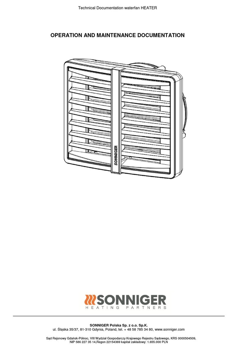
Sonniger Heater R2 User manual
Sonniger
Sonniger GUARD 100W Installation guide
