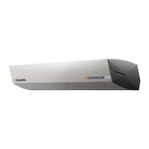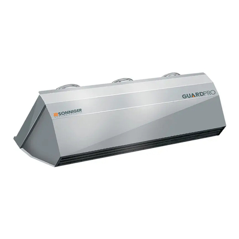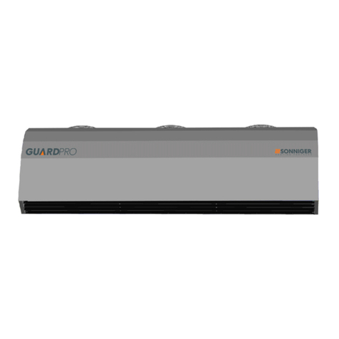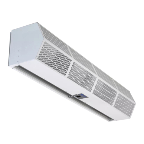
Operation and Maintenance Documentation of air curtains GUARD PRO EC v202210
5. HEAT OUTPUT RANGES
6. ELECTRICAL CONNECTION DIAGRAMS
To connect the curtain use a 3-core copper cable of minimal diameter 3x1,5mm² for two curtains (up to 6 fans) or 3x2,5mm²
for 3 curtains (up to 9 fans). The electrical installation and connection to the power supply must be done in compliance with the
existing regulations and standards for the building industry.
The electric network, to which the device is to be connected, should protect the device against overloading and short circuit. It
is necessary to use protective grounding. Any electrical installation works and the connection to supply power must be
conducted following the applicable building regulations and standards. The connection of the unit to the power supply must be
conducted by a qualified specialist who is familiar with the Manual. The fan’s motor is equipped with internal thermal protection
against overheating. A power cable and the main switch are not included in the set.
Also, the DOORSTOP door contact switch can be installed; it turns off the GUARD PRO curtain when the door is being closed
and the moment the door is being opened the GUARD PRO curtain starts operating accordingly to the parameters set in the
control panel of the device.
Fan wiring description
Ain –0-10V signal - yellow
GND – ground - blue
Tach Output – unused - white
+10V – unused - red
L – power supply - brown
N – neutral - blue
PE – protection – yellow/green
After a year of operation check the electrical connections and if needed tighten the wire connections to eliminate
potential sparkling.
0 5 10 15 20 0 5 10 15 20 0 5 10 15 20 0 5 10 15 20 0 5 10 15 20
heat output kW 13,5 10,9 7,7 4,6 3,4 18,3 16,1 13,7 11,3 8,5 23,4 21,3 19,1 16,9 14,8 28,0 25,8 23,6 21,5 19,3 32,5 30,3 28,2 26,0 23,8
˚C 6,1 9,9 13,5 17,1 21,5 8,2 12,3 16,2 20,1 23,8 10,6 14,6 18,6 22,6 26,6 12,6 16,6 20,7 24,7 28,7 14,6 18,7 22,7 26,7 30,7
water flow m
3
/h 0,6 0,5 0,3 0,2 0,1 0,8 0,7 0,6 0,5 0,4 1,0 0,9 0,8 0,8 0,6 1,2 1,1 1,0 0,9 0,9 1,4 1,3 1,3 1,2 1,0
pressure drop kPa 1,3 0,9 0,5 0,2 0,1 2,3 1,8 1,3 0,9 0,6 3,6 3,0 2,4 1,9 1,5 4,9 4,2 3,6 3,0 2,5 6,4 5,7 4,9 4,2 3,6
heat output kW 9,7 7,4 5,0 3,9 2,9 13,6 11,9 10,0 8,0 4,9 17,7 16,1 14,4 12,7 11,0 21,1 19,5 17,8 16,2 14,6 24,5 22,8 21,2 19,6 18,0
˚C 6,9 10,2 13,5 17,8 22 9,7 13,4 17,1 20,7 23,5 12,5 16,4 20,2 24 27,8 14,9 18,8 22,6 26,5 30,3 17,3 21,2 25 28,9 32,7
water flow m
3
/h 0,4 0,3 0,2 0,2 0,1 0,6 0,5 0,4 0,4 0,2 0,8 0,7 0,6 0,5 0,5 0,9 0,9 0,8 0,7 0,6 1,1 1,0 0,9 0,9 0,8
pressure drop kPa 0,7 0,4 0,2 0,1 0,1 1,3 1,0 0,8 0,5 0,2 2,1 1,8 1,4 1,1 0,9 2,9 2,5 2,1 1,8 1,5 3,8 3,3 2,9 2,5 2,1
heat output kW 6,9 5,2 4,3 3,4 2,5 10,4 9,0 7,4 5,5 4,0 13,8 12,5 11,1 9,8 8,4 16,4 15,2 13,9 12,7 11,3 19,1 17,8 16,5 15,3 14,0
˚C 7,3 10,4 14,5 18,6 22,6 11 14,5 17,9 20,8 24,2 14,6 18,2 21,8 25,3 28,9 17,4 21 24,7 28,4 31,9 20,1 23,8 27,5 31,1 34,8
water flow m
3
/h 0,3 0,2 0,2 0,1 0,1 0,5 0,4 0,3 0,3 0,2 0,6 0,5 0,5 0,4 0,4 0,7 0,7 0,6 0,5 0,5 0,8 0,8 0,7 0,7 0,6
pressure drop kPa 0,4 0,2 0,2 0,1 0,1 0,8 0,6 0,4 0,3 0,1 1,3 1,1 0,9 0,7 0,5 1,8 1,6 1,3 1,1 0,9 2,4 2,1 1,8 1,6 1,3
0 5 10 15 20 0 5 10 15 20 0 5 10 15 20 0 5 10 15 20 0 5 10 15 20
heat output kW 20,6 17,3 13,9 10,0 4,7 26,6 23,5 20,5 17,5 14,1 33,5 30,5 27,4 24,4 21,4 39,7 36,7 33,7 30,7 27,6 46,0 42,9 39,9 36,9 33,9
˚C 6,6 10,6 14,5 18,2 21,5 8,5 12,6 16,6 20,6 24,5 10,8 14,8 18,8 22,8 26,9 12,8 16,8 20,8 24,9 28,9 14,8 18,8 22,8 26,9 30,9
water flow m
3
/h 0,9 0,8 0,6 0,4 0,2 1,2 1,0 0,9 0,8 0,6 1,5 1,3 1,2 1,1 0,9 1,7 1,6 1,5 1,3 1,2 2,0 1,9 1,8 1,6 1,5
pressure drop kPa 3,4 2,5 1,7 0,91 0,2 5,4 4,3 3,4 2,5 1,7 8,2 6,9 5,6 4,5 3,6 11 9,6 8,2 6,9 5,7 14 13 11 9,6 8,2
heat output kW 14,1 11,8 9,1 5,2 3,8 18,7 16,6 14,3 12,0 9,5 23,5 21,4 19,3 17,2 15,0 27,9 25,8 23,6 21,5 19,4 32,2 30,1 28,0 25,9 23,8
˚C 8 11,6 15,1 18 22,2 10,6 14,4 18,1 21,8 25,4 13,3 17,1 20,9 24,7 28,5 15,8 19,6 23,4 27,2 31 18,2 22 25,8 29,6 33,4
water flow m
3
/h 0,6 0,5 0,4 0,2 0,2 0,8 0,7 0,6 0,5 0,4 1,0 0,9 0,8 0,8 0,6 1,2 1,1 1,0 0,9 0,9 1,4 1,3 1,2 1,2 1,0
pressure drop kPa 1,7 1,2 0,8 0,3 0,2 2,8 2,3 1,7 1,2 0,8 4,2 3,6 2,9 2,4 1,9 5,7 5,0 4,2 3,6 2,9 7,4 6,6 5,7 5,0 4,2
heat output kW 10,7 8,7 5,8 4,5 3,3 14,5 12,7 10,9 9,1 6,9 18,3 16,7 15,0 13,4 11,6 21,7 20,0 18,4 16,8 15,1 25,0 23,4 21,8 20,1 18,5
˚C 9,1 12,4 15 18,8 22,8 12,3 15,8 19,3 22,7 25,9 15,6 19,2 22,8 26,4 29,9 18,5 22,1 25,7 29,3 32,9 21,3 24,9 28,6 32,2 35,8
water flow m
3
/h 0,5 0,4 0,3 0,2 0,1 0,6 0,5 0,5 0,4 0,3 0,8 0,7 0,6 0,6 0,5 0,9 0,9 0,8 0,7 0,6 1,1 1,0 1,0 0,9 0,8
pressure drop kPa 1 0,7 0,34 0,21 0,1 1,8 1,4 1,0 0,7 0,5 2,7 2,2 1,9 1,5 1,1 3,6 3,1 2,7 2,2 1,9 4,7 4,1 3,6 3,1 2,7
90/70
inlet air temperature
air flow 9100 m
3
/h (speed 3)
air flow 5150 m
3
/h (speed 2)
air flow 3400 m
3
/h (speed 1)
inlet air temperature
air flow 6500 m
3
/h (speed 3)
air flow 4100 m
3
/h (speed 2)
air flow 2750 m
3
/h (speed 1)
inlet/outlet water temperature
50/30 60/40 70/50 80/60
inlet/outlet water temperature
50/30 60/40 70/50 80/60 90/70


