Sonostar BProbe User manual

Wireless Probe Type
Ultrasound Scanner
BProbe
User's Guide
No.:SS-IFU-1501-03 Versions:A/2
Date:2021.12

1. Introduction
The Wireless Probe Type Ultrasound Scanner is the new generation instruments
for bladder volume calculating with the outstanding feature of wireless.
Different from traditional ultrasound scanner with a cable connecting from probe to
main unit, no cable appears at the end of the probe of the Scanner. The probe of a
Scanner is highly integrated with ultrasound image processing, power management and a
wireless signal provider to be connected by the main unit. Unlike traditional devices, the
display part displays images through the iPad.The Probe contains a WiFi module that can
be connected to the iPad. With the Probe be connected through WiFi and the App’s
running, enjoy your days of working without the trouble making by cables.
This manual is intended to provide a through overview of the Scanner and should
be carefully read before starting operating the device.
Thank you for your trust in us to provide for your bladder volume calculating
needs.
1.1. Signs and Meaning
Sign
Meaning
Caution! Please consult the accompanying document.
Consult the user manual
Type BF applied part
Degree of IP protection
Non-ionizing electromagnetic radiation
Manufacturer
Date of manufacture
Serial number
Keep dry
IPX5
Prevent the water from the nozzle from invading in all directions and cause damage
to the electrical apparatus.

1.2. SPECIALIST
1)
Intended Use
The ultrasound system is intended for examining the adult, pregnant woman and
children. It is mainly used for measuring urinary volume of bladder.
2)
Contraindication
The basic equipment is not suitable for injuries or acute inflammatory site
inspection, to avoid cross infection.
The basic equipment is not suitable for gas containing organs such as lung,
stomach and intestine.
The basic equipment is not intended for ophthalmic use or any use causing the
acoustic beam to pass through the eye.
3)
Physicalcharacteristics
Size 156 mm x 60 mm x 20 mm
Weight 450g
4)
Environmental
Operations
Storage and Transportation
Relative Humidity
25% to 80%,
non-
condensing
25% to 93%, non-condensing
Ambient Temperature
5°C to +40°C
-20°C to +55°C
Atmospheric Pressure
700hPa to
1060hPa
700hPa to 1060hPa
5)
Electronic
Input:5Vd.c. 1A
Battery Capacity:model(SNP-4200)3.8Vd.c. 4200mAh
Continuous working time:2 hours
Waterproof: IPX5
6)
Probe
Frequency: 2.6MHz
Display accuracy: 1ml
Measuring range: 20 – 999ml
Measuring accuracy: 20-99ml: ≤±10ml
100-999ml: ≤10%
7)
Printer
Communication mode: Bluetooth
8)
Display
Display main unit: iPad Series
Display Mode: B-Mode
Gray Scale: 256 levels
9)
other
Type of protection against
electric shock
Internally powered
Degree of protection
against electric shock
Type-BF applied part

Operation mode
Continuous working
Applied part
Probe
2. Getting started
FOR YOUR PROTECTION, please read these safety instructions completely
before applying power to, or operating the system.
2.1. Unpacking
The Scanner is carefully packed to prevent damage during shipment. Before
unpacking, please note any visible damage to the outside of the shipping containers.
Items should be checked in order to ensure that all ordered items have been
received. The following table lists the items which should be received with each
particular system.
Table 2-1 Items List
ITEMS
INCLUDED
scanner(4D Scan Wireless Ultrasound Probe)
√
USB Cable for Charging
√
Operators’ Manual
√
APP
√
IPad
Optional
Each item should be examined for any noticeable defects or damage that may
have occurred during shipment although it is packed carefully. If any defect or
damage exists, please contact to your local representative immediately to report the
problem.
2.2. Installing
If the Bladder Scanner App is not installed in your iPad, Please Get it from App
Store or from distributors freely.
To obtain software from Apple App Store, open the App Store on the iPad, enter
bladerscanner in the search bar, and then click to install.

2.3. Starting probe
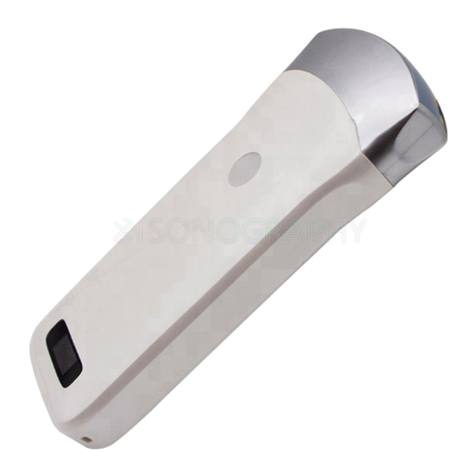
Figure 2-1 Wireless Ultrasound Probe
The Wireless Connection Indicator and the Battery Capacity Indicator on the
probe may be invisible before the probe is turned on.
Press the button to turn on the probe. The Battery Capacity Indicator will be
light to indicate the capacity of the battery. The four grids of the indicator imply the
battery capacity. (Probe charging will be described in section 4.1.)
Seconds after the probe turned on, the Wireless Connection Indicator will be
light and blinking to notice that the probe is ready for a wireless connection from the
iPad.
The probe can be turned off by hold down the button for seconds. When the
probe is off, the indicators will be turned off.
The concave (4) is the place for loading pressure by thumb. Suitable pressure is
applied to the probe so the probe can couple to body perfectly.
2.4. Wireless connection
When the probe is waiting for a wireless connection as described in previously,
launch the Settings of iPad, turn on the Wi-Fi (if not on), Find the SSID of the probe.
The SSID is like: “WB-1 GMBGBB001”, the suffix after “WB-1” is a code generated
from Serial Number. Connect to the SSID with the password same as the Serial
Number (in lower case). The Serial Number is in the form like “WBPBGBB001” with

the prefix of “WBP”. It can be found on the surface of the probe.
After Wi-Fi is connected, launch the Bladder Scanner App, after the connection
from the app to the probe is confirmed, the Wireless Connection Indicator on the
probe will be light with no blinking.
Every connection steps are done. The operations of using the system to finish
ultrasonography task will be described in the next section.
3. APP operation
3.1. Ultrasound scan
Figure 3-1 main menu
After the probe is connected, launch the App, the Main Screen will show similar
in Figure 3-1. (No image is visible when the App is firstly launched.)
The probe connection status label(5) indicates the status of the connection
between the probe and the main unit(like iPad).If the connection is well the label is
green and prompt “ready” otherwise the label is gray and the prompt is”probe”.

There is a center indicate line (3) in the middle of the image area .
Touch the patient information area (2) to enter the patient interface
to edit or create a new case. Please refer to section 3.2 for detail
information.
Press the Run/Freeze Button to run and Freeze the probe. When the
Image come to shown on the Image Area (1), the sample indicator (4)
will turn green from gray if the proper image has been
obtained( please refer to section 3.3 for detail information).
When the image is frozen, the 12 sections images and the calculating
volume value will be shown on the screen. Users can press “print”
(6)( please refer to section
3.4fordetailinformation)buttontoprintthecurrentresult.
Users can use the Save image button (7) to save the image and patient
information, Review button(8) to review the stored images( please
refer to section 3.5for detailinformation)..
Press the Setting button (9) to set the parameters, including gain
and channel(pleaserefertosection3.6fordetailinformation).
Note: In all interfaces, if the button is blue means that the prompt
operate is effective .if the button is gray indicates it is an invalid
operate.
3.2. Patient information
Figure 3-2 patient information
Touch the patient information area (2) (Figure3-1)to enter the patient
interface ,then touch the boxes after the labels, the ID, Name, Gender, Age and the
Operator can be input or chosen.

When you touch “Create New Case”, all the information will be cleared.
The Phantom Mode is default as closed.
After all the information has been set ,you can touch “OK” to save or “Cancel” to
give up, then the patient information interface will be closed.
3.3. Scanning
3.3.1 Prepare probe
Figure 3-3 pre-Scanning
Before scanning, please use some acoustic gel on patient abdomen and place
the probe. The thumb is place on the concave and the button can be pressed by
thumb pulp. For good coupling between the probe and abdomen, Suitable pressure
should be applied to probe by thumb.
3.3.1. Pre-scanning mode
Pre-scanning helps operator to locate bladder correctly to obtain accurate result.
If the connection is done, press the Button once on the probe to start pre-scanning
and the real-time B-mode ultrasound image displays on the screen.
When the mode is pre-scanning and the Bladder is in the center of image , the
cycle ((4) Figure3-1) on the right upper will be green.

Figure 3-4 pre-Scanning
3.3.2. Scanning mode
When the cycle is green, press the button again to enter scanning mode. The
device will obtain and deal with images. When the probe stops vibrating it means the
scanning is finished. The 12 scanning images and the measurement result will be
displayed on the screen (see Figure 3-3 scanning result menu).
Figure 3-5 scanning result menu

On the scanning result menu, there are 12 section images. The serial number of
the image is shown on the left upper of the single image. You can touch one single
image to be full-screen to see the details, and swipe left/right to see the
previous/next image and touch again shift back to total scanning result menu.
3.4. Print a case report
3.4.1. Reload a thermal paper roll
The Bluetooth printer uses the thermal paper roll, follow the steps to reload a
roll:
Figure3-6 reload a paper roll
1)
Turn off the printer;
2)
Open the housing cover;
3)
Take out the old roll(if have),put in a newone;
4)
Pull the paper out 1cm off the housing and close the cover(there will be a
creaking)
5)
Try printing a case report to check if the paper roll was reloaded rightly.
Note: if the printer doesn’t work rightly, please reload the roll.
3.4.2. Printer connection
Before you print the case report, you should connect the printer, named as
“MPT-II-4” to the main unit by Bluetooth.
Turn on the printer, open the Bluetooth settings of the main unit, then connect
the printer. The “power” LED will be red if the connection is well otherwise the LED
will be red and blinking. The printed case report is shown as Figure3-5

Figure3-7 printed case report
Note: if the printer is not used the POWER LED will be blinking between red and
blue.
Note: if you charge the printer, the FEED LED will be blue and blinking.
3.5. Storage and Review the image
Press the button ”Save” to save the images and the patient
information(including ID, Name etc) .The saved data can be recalled by touch the
button “Review”
Note: Not only the scanning result menu can be stored but also a single picture
in the menu.
When you touch “Review” button, there will be a small dialog box, as shown in
Figure 3-6, then you can choose any photo you need to review.
Figure 3-8 review menu

3.6. Set parameter
Figure 3-9 setting menu
1)
Gain
When t a new gain is needed, the add and subtract button can used to change
the gain from 30 to 105 dB
2)
Wireless Channel
When the system is using in an environment where the Wi-Fi channel is
crowded, A new channel can be selected for the probe by pick a channel from the
picker and tap Select button. After 2 seconds, please restart the probe to make the
new channel available and the user also have to reconnect the probe with a different
SSID.
4. Maintance
4.1. Battery Charge
When battery is low, it is necessary to recharge the probe. There are two charging
methods you can take.
1)
Charging with USB Cable
Pull the insertion at the end of the probe, then connect the USB Charger and
USB Cable with the probe to charge the probe as shown in the left picture of Figure
4-1.

Figure 4-1 Charge the Probe
2)
Wireless Charging
Applying power to the wireless charging pad, put the probe on the portable
wireless charger as shown in the right picture of figure 4-1.if the relative position is
right ,there will be a notification tone and the capacity indicator on the probe will be
light.
When in charging, the battery indicator will be blinking and the grids indicate
the capacity of the battery charged.
If four grids all light and the indicator not blinking means the battery is fully
charged. Unplug the USB cable and the insertion should be carefully plugged to make
the probe able to keep out water.
4.2. Cleaning and Disinfection
4.2.1 Precaution and warnings
When cleaning and disinfecting:
• Follow the procedures in the order they are described in this guide, without
skipping steps.
• Follow the manufacturer's instructions, recommendations, and guidelines for
cleaners and disinfectants, as well as your regional regulations.
• Check expiry dates, concentration, and efficacy of the chemicals used.
• Wear the appropriate personal protective equipment (PPE), such as eyewear
and gloves, as recommended by the chemical manufacturer.
• Repeated use and cleaning over the course of the scanner ’ s life may
deteriorate its cleanliness.
• Using incompatible solutions to clean the scanner may damage its surface.
• Cleaning or disinfecting the scanner while the battery is installed may cause
the battery to short-circuit and overheat, causing an electric shock or burn.
WARNING: During an emergency where the scanner is used to examine multiple
patients in a short period of time, the lack of proper cleaning and disinfecting

between patients may spread infections to other patients and users.
Put on a condom that meets the medical qualification for use, dispose the used
condom in the medical waste recycling box after use, and then disinfect and clean
the probe
4.2.2 Cleaning and Disinfection the probe
1. Thoroughly dry the instrument with a clean, soft cloth before using.
2. To clean the probe, Use a soft cloth dampened with 75%Alcohol to wipe the
Probe until it is thoroughly cleaned.
3. To remove all traces of disinfectant solution, wipe the instrument with a clean
soft cloth dampened in sterile water or potable tap water. Wiping the device three
separate times to remove all residual disinfectant is recommended.
4. Verify that all gel, particulate matter, and bodily fluids have been removed.
5. Dispose the soft cloth and the instrument used to insert the cloth.
4.3. Storage
When not in use, it is recommended that the equipment should be put in the case.
While stored the equipment should be protected from temperature extremes.
4.4. Caution
This equipment has been tested and found to comply with the limits for a Class B digital device,
pursuant to part 15 of the FCC Rules. These limits are designed to provide reasonable protection
against harmful interference in a residential installation. This equipment generates uses and can
radiate radio frequency energy and, if not installed and used in accordance with the instructions,
may cause harmful interference to radio communications. However, there is no guarantee that
interference will not occur in a particular installation. If this equipment does cause harmful
interference to radio or television reception, which can be determined by turning the equipment
off and on, the user is encouraged to try to correct the interference by one or more of the
following measures:
-Reorient or relocate the receiving antenna.
-Increase the separation between the equipment and receiver.
-Connect the equipment into an outlet on a circuit different from that to which the receiver is
connected.
-Consult the dealer or an experienced radio/TV technician for help.
This device complies with part 15 of the FCC Rules. Operation is subject to the following two
conditions: (1) This device may not cause harmful interference, and (2) this device must accept
any interference received, including interference that may cause undesired operation.
Any Changes or modifications not expressly approved by the party responsible for compliance
could void the user's authority to operate the equipment.
PRECAUTION 1: Put on a condom that meets the medical qualification for use, dispose the
used condom in the medical waste recycling box after use, and then disinfect and clean the probe
according to Section 4.3.
PRECAUTION 2: The device shall be operated by professional physicians, and should wears
gloves before use.
WARNING :The user and/or patient should be reported “any serious incident that has
occurred in relation to the device”to the our company and the competent authority of the
Member State.
4.5. TROUBLE SHOOTING
Inspect: check if the probe and the scanner is properly connected.

Fault handling:
Serial number
problem
Solution method
1
No response after pressing the power switch
Check wires and plugs
2
Display on the screen to show the band or
snowflake like interference
1.Check if any other device is
started
2.Check the electric field or
magnetic field in the surrounding
environment.
3
The image area is dark.
1.adjusting brightness
4.6. Disposal
*Warning: products should not be discarded at will.
-Battery recycling meets local requirements.
-Recycling of waste electrical and electronic products should comply with local laws and
regulations.
WARNING :The user and/or patient should be reported “any serious incident that has
occurred in relation to the device”to the our company and the competent authority of the
Member State.
5. Safety
The operation safety is the most important concern of the designer. To ensure the safety and
efficiency of the system, the operator should read carefully about this chapter before using the
system.
5.1 Safety Instructions
Read and understand all precautions in this manual before using the system.
Keep this manual with the system at all times. Periodically review the procedures for operation and
safety precautions.
To maintain the performance and safety of the system, electric and mechanical safety inspections for
the system should be performed periodically by professional technicians in less than 6 months.
5.1.1Electric Safety
●The biocompatibility of this product has been verified, in normal circumstances, it will not
bring harm to the operator or patient.
●No modification of this equipment is allowed.
●If any operator requests more information such as circuit diagrams, parts list and product
descriptions, for repairs carried out by qualified technical personnel, please contact us.
●Warning against activation of transducer assembly intended for intra-corporeal use outside
patient’s body if transducer assembly does not comply with emc requirements (may cause
harmful interference with other equipment)
●Please check and replace the battery periodically, please use batteries as power supply when
there is any problem with protective earthing
●Warning: Class I equipment, to avoid the risk of electric shock, the equipment must only be
connected to a supply mains with protective earth.
●Do not place the multi-socket outlet on the floor.

●Do not connect other devices to multi-socket outlet; otherwise, the rated output power may be
exceeded and failure may be resulted.
●The multi-socket outlet can only be used to provide power to the recommended peripheral
devices of this system.
●Select the qualified multi-socket outlet with protective grounding, and ensure its maximum
output power doesn't exceed the required one of this system.
●If the non-medical electric equipment connected to the system is powered by the movable
multi-socket outlet with the isolation transformer, you should connect the plug of the system to
the hospital-graded standard socket. Meanwhile, please consult the professional technician to
ensure that the connection meets the safety requirements.
●The video printer should be connected to the cable provided by the manufacturer, otherwise,
there is a danger of electric shock.
●It is recommended to connect this equipment to equipotential system. Use yellow and green
equipotential grounding cables, one end is connected to position with symbol, and other end is
connected to equipotential system. Use of potential equalization conductor together with a
reference to requirements of IEC 60601-1 for Medical Electrical System.
●Do not pour any fluid onto the ultrasound system surfaces, as fluid seepage into the electrical
circuitry may cause excessive leakage current or system failure. If carelessly pour any water onto
the system, immediately stop using the ultrasound system and contact Service Representative
immediately.
●Only use the probes provided by the manufacturer. Otherwise, the ultrasound system cannot
be performed, and an accident such as a fire may result in the worst case.
●The machine that are not serviced or maintained while in use with the patient.
●Make sure the system is powered off and power cable is disconnected before cleaning the
system. Otherwise, an electric shock may happen.
● The outer surface of the portions of transducer assembly which is intended to be
inserted into a PATIENT should be checked to ensure that there are no unintended rough
surfaces, sharp edges or protrusions which may cause harm.
● Please read the instructions and then set and control the acoustic output levels.
5.1.2Mechanical Safety
● Be careful when holding the device, for it is handhold, it may fall.
● Do not use shell cracking equipment.

5.1.3 Accessories Safety


5.2 Principles of Using Acoustic Power
5.2.1 Biological Safety
Diagnostic ultrasound is recognized as being safe, but the risk of biological effects exists when using
it in high exposure levels and long exposure times. Thus ultrasound should be used in a prudent
manner to provide medical benefit to the patient.
5.2.2 Mechanical and Thermal Indices
The ultrasound system displays two parts: thermal Index (TI) and Mechanical Index (MI). The MI/ TI
value of the machine is real time displayed at the upper right corner, regarding how to change TI
display type, please choose: Preset → [System Preset] → [TI].
■ Meaning of MI/TI
Mechanical bioeffects are threshold phenomena that occur when a certain level of output is
exceeded. The threshold level varies with tissue type. The potential mechanical bioeffects varies
with peak pressure and ultrasound frequency. The higher the MI value, the greater the likelihood
of mechanical bioeffects occurring. There is no specific MI value theat means that a mechanical
effect is actually occurring. The MI should be used as guide for implementing the ALARA
principle.
The TI value informs the operator about the conditions that might lead to an increase in
temperature at surface of the body, within the body tissue, or at the point of focus of the
ultrasound beam on bone. That is, the TI value informs the operator about the potential
temperature rise in body tissue. It is an estimate of temperature increase in body tissue with
specific properties. The actual amount of an temperature rise is influenced by factor such as
tissue type, vascularity, mode of operation and others. The TI value should be used as a guide
for implementing the ALARA principle. Depending on the examination and type of tissue
involved, TI could be one of three types.
Soft Tissue Thermal Index (TIS) is used when imaging soft tissue only, it provides an estimate
of potential temperature rise in soft tissue.
●Bone Thermal Index (TIB) is used when bone is near the focus of the image as in the
third cropester OB examination, it provides an estimate of potential temperature rise in the bone
or adjacent soft tissue.
●Cranial Bone Thermal Index (TIC) is used when bone is near the skin surface as in
transcranial examination, it provides an estimate of potential temperature rise in the bone or

adjacent soft tissue.
■ Precision of MI/TI
TI and MI values are displayed in real time on the screen. The operator should observe these
index values during examinations and ensure that exposure time and output values are
maintained at minimum amounts needed for effective diagnosis. The MI and TI precision is 0.1.
5.2.3 Acoustic Output Statement
5.2.3.1 The Influencing Factors of Acoustic Uncertainty
When estimating accuracy of displayed numerical values, many factors are considered:
●The probe changeability
●The system changeability
●Changeability and accuracy of measurement
●Possible operating conditions and testing numbers needed to obtain displayed result accuracy
of the diagnostic system
●Whether the display accuracy depends on specific system combination, mode combination ,
probe component and launch mode combination, or all of above
●Algorithm accuracy of the system software used to calculate the MI/TI
●Approximation engineering method used in real time computation
5.2.3.2 Differences between Actual and Displayed MI and TI
For many assumptions used in the process of measurement and calculation, actually they are
conservative. For most organizations path, high estimate is made in the measurement and calculation
process of tissue exposure intensity. For example, using attenuation coefficient 0.3dB cm-1 MHz-1
much lower than the actual human tissue attenuation coefficient, choosing conservative values of
tissue characteristic. Therefore, displayed MI and TI values should be relative information for
reference, they serve to indicate to the operator whether a particular setting of the system increases or
decreases the possibility of Thermal or Mechanical effect, used to help the operator be careful to use
ultrasonic diagnostic system and follow the ALARA principle, these values cannot be equal to actual
values.
5.2.3.3 Uncertainty of Measurement
Sound pressure is the most basic data of sound field measurement, and other sound field parameters
can be deduced from sound pressure, so when analysing measurement uncertainty, only take sound
pressure for analysis and uncertainty of other parameters can be deduced from the sound pressure.
Measurement uncertainty mainly include repeated measurement uncertainty and the system
uncertainty, the system uncertainty is an order of magnitude higher than repeated measurement
uncertainty, so the main analysis is the system uncertainty. Mainly decided by the following factors:
Table of contents
Other Sonostar Scanner manuals
Popular Scanner manuals by other brands

Hitachi
Hitachi EUB-5500 Technical guide
PRECISION DIGITAL
PRECISION DIGITAL Minimux II PD138 instruction manual

Zebex
Zebex Z-2170 Plus user manual

Keithley
Keithley 7057A instruction manual

Canon
Canon DR-6050C - imageFORMULA - Document Scanner supplementary guide
Plustek
Plustek SmartOffice PS3180U user manual
