Pro's Kit MT-7071 User manual

MT-7071 LCD Cable Length Toner & Probe Kit
Getting Started Guide
INSTRUCTION
MT-7071 Transmitter/Remote Unit:
1. RJ45 (8 pin) connectors: Used for cable mapping and verifying cable status of RJ45 (8 pin) LAN cable with
remote unit; with tone generator for wire tracing; for measuring cable length to open without remote unit.
Caution! Do not plug in live wire that over 5mA, AC 60V /DC 48V to RJ45 (8 pin) jack.
2. RJ11(6 pin) Connectors:Used for cable mapping and verifying cable status of RJ11 (6P/6C/4C/2C) phone cable
with remote unit; with tone generator for wire tracing; for measuring cable length to open without remote unit. Use
alligator clip patch cord for cable mapping, cable length measuring and verifying cable status of single conductor
cable or two conductor cable.
Caution! Do not plug in live wire having over 5mA, AC 125V/DC 100V to RJ11 (6 pin) jack.
3. BNC Connectors:Used for cable mapping and verifying cable status of BNC Coax cable with remote unite; with
tone generator for wire tracing; for measuring cable length to open without remote unit. Use adaptor for testing RF
cable (such as F、RCA、TNC、M connectors).
Caution! Do not plug in live wire having over 5mA, AC 125V/DC 100V to BNC (2pin) connector.
4. LCD Display:For indicating function and display test result.
5. Battery low indicator: When the battery is lower than DC 7.0V, LCD will show flash 「」icon. Please replace
battery.
6. 「」Function enter push button:Press this button to enter the function.
7. 「」Function up push button:Press this button to move up arrow cursor on LCD to choose function or
increase 0.1 meters / feet / yards of calibration parameters.
8. 「」Power ON/OFF push button:Press this button to power on, push again for power off.
9. 「」Function return push button:Press this button to return to previous menu.
10. 「」Function down push button:Press this button to move down arrow cursor on LCD to choose function or
reduce 0.1 meters / feet / yards of calibration parameters.
11. Battery cover.
1 2
11
ENTER RETURN
DOWNUP
MT-7071
LCD CABLE LENGTH
TONER & PROBE
TRANSMITTER
4
3
3
2
6
7
5
9
8
10
1
Figure 1 MT-7071 Transmitter / Remote Unit
1

MT-7071 Receiver:
1. Probe:Used for wire tracing and NCV detection.
2. LED illumination:Used for dark working environment.
3. Power ON/OFF indicator:The indicator will be lit up when the switch is at LED or NCV position and the receiver
has started its functions. When the switch is at OFF position, the indicator will be lit up when pushing “ ” button
for wire tracing.
4. NCV indicator:When the probe is close to the tested object to detect the voltage, the indicator will light up if the
object carried AC90~1000V. If the indicator did not light up, there is no voltage detected from the object or the AC
voltage is less than 90V.
5. Signal status indicator:When doing cable mapping by probe, if the indication LEDs (1~8) more light up, the
signal is stronger.
6. Volume control:By adjusting the volume from high to low to adjust the sensitivity of probe, move the position of
receiver from 30 to 10cm to find out which cable you are tracing.
7. Earphone jack Φ3.5mm:Earphone can be used when the working area is noisy.
8. Function selection:3 Position mode switch (NCV、OFF、LED)
9. Speaker:When “SCAN” feature is working, if the speaker is louder, the signal is stronger.
10. 「」Locating and Isolating cables function push button:When pushing the “ ” button, the feature
starts and the battery indicator light will be on.
11. RJ45(8 pin) connectors:Used Only for RJ45 (8 pin) Lan cable mapping. When used for RJ45 (8 pin) LAN cable
mapping and wire troubleshooting, please connect the cable terminal to RJ45 (8 pin) jack of MT-7071 Transmitter,
then start the function. (only for 1 to 1 test )
Caution! Do not plug in any live wire to the RJ45 (8 pin) jack.
12. Battery cover.
LED
OFF
NCV
1
2
7
43
5
9
12
8
2
6
MT-7071
LCD CABLE LENGTH
TONER & P ROBE
RECEIVER
SCAN
10
11
Figure 2 MT-7071 Receiver Diagram
OPERATION
FIRST USE GUIDE
If this is your first operation, please follow the instruction to set Language, Auto power off time and Unit as below
1. Select Language:
2

2. Auto Power Off time setting:
3. Select Unit:
CABLE MAPPING
1. Connect cable to transmitter and remote unit:
LCDCABLELENGTH
TONER&PROBE
MT-7071
TRANSMITTER
ENTER
RETURN
DOWN
UP
Figure 3 Validating Cable Maps
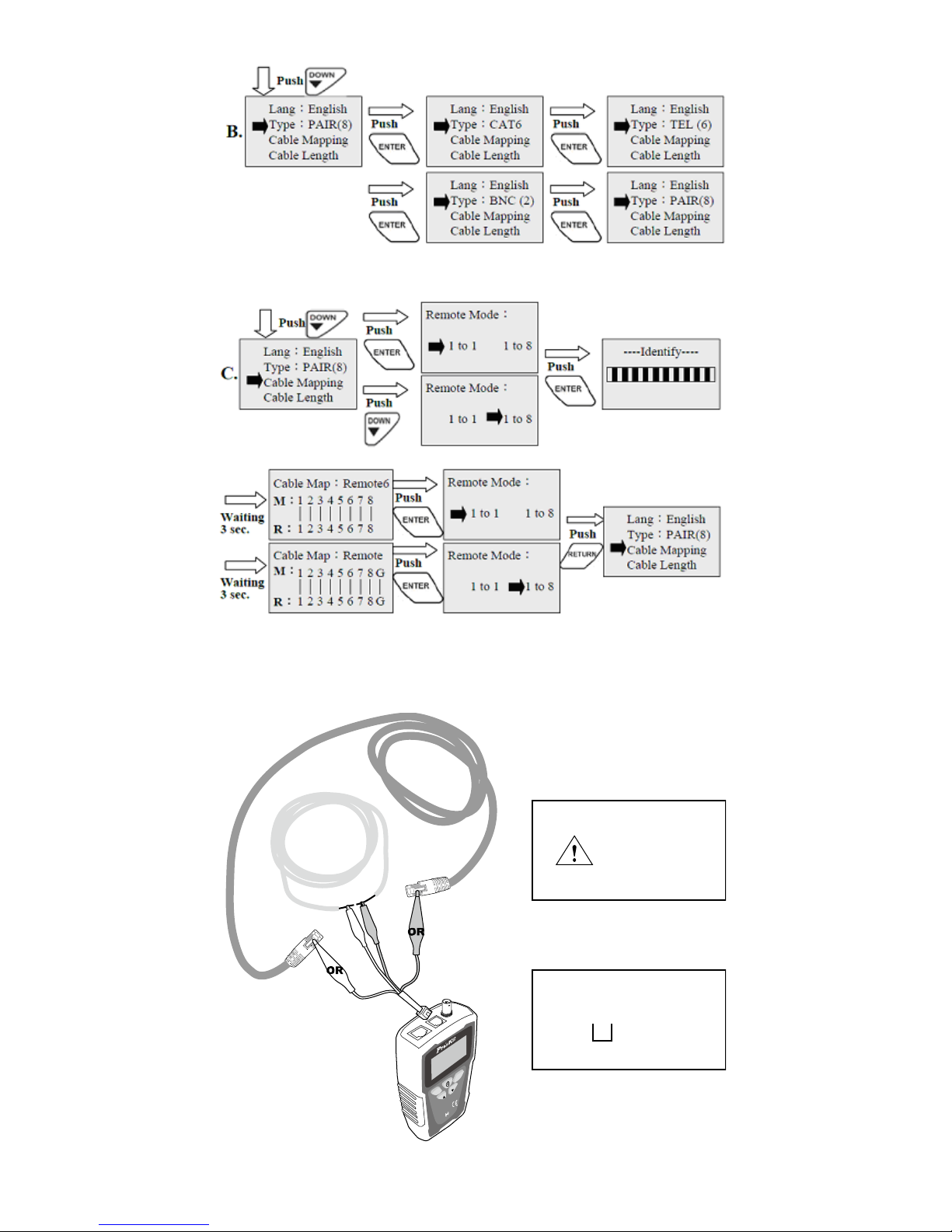
2. Select cable type you want to test:
3
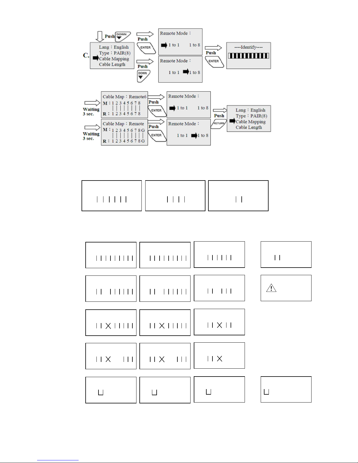
3. Cable Mapping Test:
4.Test Result
4-1.Test result for cable mapping with standard remote unit:
Cable Map:Remote
Telephone Cable (6P/6C) Telephone Cable (6P/4C) Telephone Cable (6P/2C)
Cable Map:Remote Cable Map:Remote
M:
123456
123456
R:
M:
X2345X
X2345X
R:
M:
XX34XX
XX34XX
R:
Good
Figure 4-1 Telephone Cable 6P/6C、6P/4C、6P/2C
Cable Mapping with standard remote unit
M:
123456
123456
R:
Telephone Cable (6P/6C)
1~6
Cable Map:Remote
M:
R:
BNC Coaxial Cable (2 pin
1、G
Cable Map:Remote
Good
1 or G
Opens
M:
12X456
12X456
R:
Cable Map:Remote
Short
M:
123456
123456
R:
Cable Map:Remote
Short mapping:
123456
Short mapping:
1G
M:
1234XX
1234XX
R:
Cable Map:Remote
M:
123456
123456
7
7
8
8
G
G
R:
M:
123456
123456
7
7
8
8
G
G
R:
Cable Map:Remote
RJ45 Lan Cable (8+1 pin)
1~8、G
Cat. 6 Lan Cable (8+1 pin)
1~8、G
Cable Map:Remote
Good
M:
12X456
12X456
7
7
8
8
G
G
R:
M:
12X456
12X456
7
7
8
8
G
G
R:
Cable Map:Remote Cable Map:Remote
3 Opens
M:
123456
123456
7
7
8
8
G
G
R:
M:
123456
123456
7
7
8
8
G
G
R:
Cable Map:Remote Cable Map:Remote
3、4 Crossed
pairs
12345678G
Short mapping:Short mapping:
3、4
Shorts
M:
1234XX
1234XX
7
7
8
8
G
G
R:
12345678G
M:
1234XX
1234XX
7
7
8
8
G
G
R:
Cable Map:Remote Cable Map:Remote
3、4 Crossed
pairs &
5、6 Opens
Cable open or
too short!
1G
1G
Figure 4-2 the test result instruction for cable mapping
with standard remote unit
4

4-2. The Test Result Instruction For Cable Mapping With Multi Remote Unit (ID#1~#8):
Cable Map:Remote 6
Telephone Cable (6P/6C) Telephone Cable (6P/4C) Telephone Cable (6P/2C)
Cable Map:Remote 6 Cable Map:Remote 6
M:
123456
123456
R:
M:
X2345X
X2345X
R:
M:
XX34XX
XX34XX
R:
Good
Figure 5-1 Telephone Cable 6P/6C、6P/4C、6P/2C
Cable Mapping with multi remote units
Cable Map with multi remote units ID#1~ID#8
M:
123456
123456
7
7
8
8
R:
M:
123456
123456
7
7
8
8
R:
Cable Map:Remot 6
RJ45 Lan Cable (8 pin)
1~8
Cat. 6 Lan Cable (8 pin)
1~8
Cable Map:Remot 6
Good
M:
12X45X
12X45X
7
7
8
8
R:
M:
12X45X
12X45X
7
7
8
8
R:
Cable Map:Remot 6 Cable Map:Remot 6
3 Opens
M:
123456
123456
7
7
8
8
R:
M:
123456
123456
7
7
8
8
R:
Cable Map:Remot 6 Cable Map:Remot 6
3、4 Crossed
pairs
12345678
Short mapping:Short mapping:
3、4
Shorts
M:
12 XXXX
12 XXXX
7
7
8
8
R:
12345678
M:
12 XXXX
12 XXXX
7
7
8
8
R:
Cable Map:Remot 6 Cable Map:Remot 6
3、4 Crossed
pairs &
5、6 Opens
M:
123456
123456
R:
Telephone Cable (6P/6C)
1~6
Cable Map:Remot 6
M:
R:
BNC Coaxial Cable (2 pin
)
1、G
Cable Map:Remot 6
Good
1 or G
Opens
M:
12XX56
12XX56
R:
Cable Map:Remot 6
Short
M:
123456
123456
R:
Cable Map:Remot 6
Short mapping:
123456
Short mapping:
1G
M:
XX3 4 XX
XX3 4 XX
R:
Cable Map:Remot 6
Cable open or
too short!
1G
1G
Figure 5-2 the test result instruction for cable mapping
with multi remote unit (ID#1~#8)
MEASURE LENGTH, LENGTH CALIBRATION AND RECALL PARAMETER
1. Connect cable to transmitter:
LCDCABLELENGTH
TONER &PROBE
MT-7071
TRANSMITTER
ENTER
RETURN
DOWN
UP
Figure 6 Cable Length Calibrations and Measurement
5
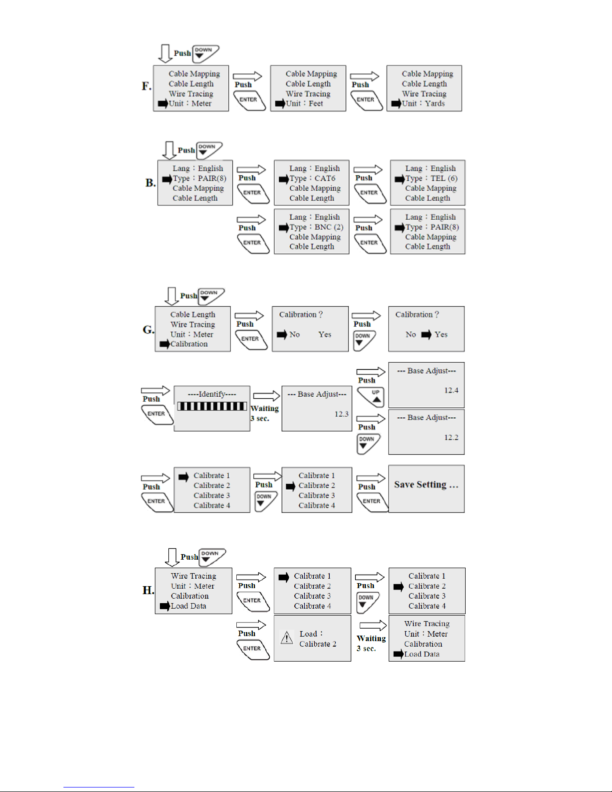
2. Select Unit:
3. Select cable type you want to test:
4. Calibration parameters setting:
5. Calibration parameters Recall:
6
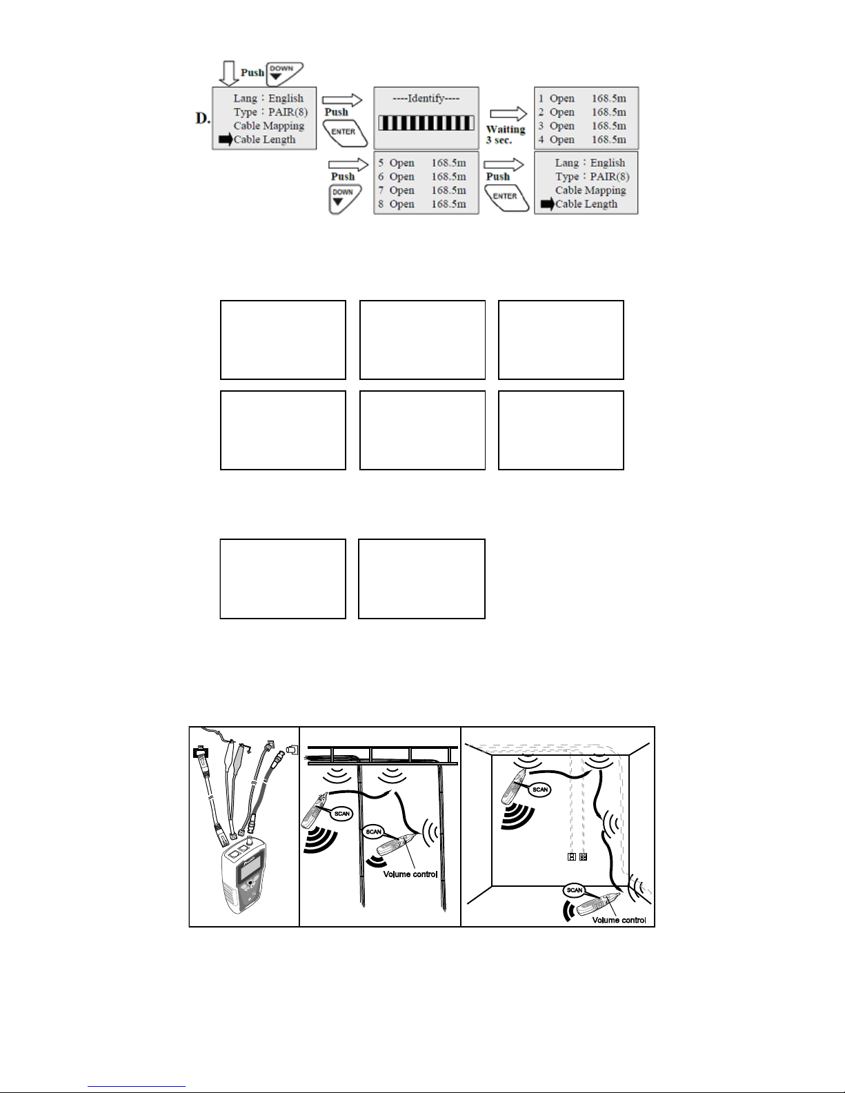
6. Measure Length:
7. Test result for measuring cable length:
RJ45 Lan Cable (8 pin)
8 pin same distances
to open
8 pin same distances
to open
6 pin same distances
to open
2 pin same distances
to open
2 pin same distances
to open
1
Open
Open
Open
Open
Open
Open
Open
Open
Open
Open
Open
Open
Open
Open
Open
Open
Open
Open
Open
Open
Open
Open
Open
Open
Open
Open
168.5m
168.5m
168.5m
168.5m
2
3
4
Cat.6 Lan Cable (8 pin)
1
168.5m
168.5m
168.5m
168.5m
2
3
4
5
168.5m
168.5m
168.5m
168.5m
6
7
8
5
168.5m
168.5m
168.5m
168.5m
6
7
8
Telephone Cable (6 pin
)
1
168.5m
168.5m
168.5m
168.5m
2
3
4
BNC Coaxial Cable (2 pin)
1
168.5m
168.5m
2
Double conductor wire(2 pin)
1
168.5m
168.5m
2
5
168.5m
168.5m
6
Figure 7 Test result for measuring Cable length to opens are the same
LOCATING AND ISOLATING CABLES
1. Connect cable to transmitter and receiver
1-1. Locating Individual wire pairs with the MT-7071 analog function:
M
T
-7071
L
CDCABLELENGTH
T
ONER&P
R
OBE
RECEIVER
SCAN
M
T
-7071
L
CDCABLELENGTH
T
ONER&P
R
OBE
RECEIVER
SCAN
M
T
-7071
L
CDCABLELENGTH
T
ONER&PR
OBE
RECEIVER
SCAN
M
T
-7071
L
CDCABLELENGTH
T
ONER&P
R
OBE
RECEIVER
SCAN
LCDCABLELENGTH
TONER&PROBE
MT-7071
TR
ANSM
ITTER
ENTER
RETURN
DOWN
UP
RJ45 Jack RJ11/12 Jack
BNC
Jack
Ground
Figure 8 Locating cables
1-2. Isolating cables:
7

MT
-7071
LCDCABLELENGTH
TONER&P
ROBE
RECEIVER
SCAN
MT
-7071
L
CDCABLELENGTH
TONER&P
R
OBE
RECEIVER
SCAN
M
T
-7071
L
CDCABLE LENGTH
T
ONER&P
R
OBE
RECEIVER
SCAN
LCDCABLE LENGTH
TONER&P
ROBE
MT-7071
TRANSM
ITTER
ENTER
RETURN
DO
WN
UP
Telephone
block
RJ45 Jack RJ11/12 Jack
BNC Jack
Volume control
Volume control
Volume control
Figure 9 Isolating Cable
2. Select cable type you want to test:
3. perform the wire tracing function to find out the target cable:
LIVE TELECOMMUNICATION EQUIPMENT AND ROUTER TEST
1. Connect RJ-45 (8P/8C) cable to transmitter and working router:
LCDCABLELENGTH
TONER&P
ROBE
MT-7071
TRANSMITTER
ENTER
RETURN
DOWN
UP
RJ45 shielded Lan cable :
Continuity
Short mapping:
12345678G
RJ45 shielded Lan cable :
Faule
Short mapping:
12 34 5678G
RJ45 unshielded Lan cable :
Continuity
Short mapping:
12 34 5678
RJ45 unshielded Lan cable :
Faule
Short mapping:
12345678
RJ45 Jack
Figure 10 Cable testing on working line
8
2. Select cable type you want to test:
3. Cable Mapping test:
SHIELDED LAN CABLE & CONTINUITY TEST
1. Plug alligator clip patch cord into RJ11 Jack, and another terminal connect with tested Cable:
LCDCABLELENGTH
TONER&P
ROBE
MT-7071
TRANSM
ITTER
ENTER
RETURN
DO
WN
UP
Open or unshielded:
Resistance>500Ω±100Ω
Short or shielded:
Resistance<500Ω±100Ω
Short mapping:
12 34 56
Cable open or
too short !
Testing for
continuity
Validating the
Cable ’s Shield
Figure 11 Shielded LAN Cable & Continuity Test
9

2. Select cable type you want to test:
3. Cable Mapping test:
NCV (Non-Contact Voltage) TEST
1. Turn the switch to “NCV” position, NCV tested function has been started when Power on:
AC
Socket
MT-7071
LCDCABLELENGTH
TONER&PROBE
RECEIVER
SCAN
Figure 12 Non-Contact Voltage Testing
寶工實業股份有限公司
PROKIT’S INDUSTRIES CO., LTD
http://www.prokits.com.tw
©2014 Prokit’s Industries Co., LTD. All rights reserved 2014001(C)
10
Table of contents
Other Pro's Kit Test Equipment manuals

Pro's Kit
Pro's Kit 8PK-4103IN User manual

Pro's Kit
Pro's Kit MT-7063 User manual

Pro's Kit
Pro's Kit NT-305 User manual

Pro's Kit
Pro's Kit NT-309 User manual

Pro's Kit
Pro's Kit MT-7062 User manual

Pro's Kit
Pro's Kit MT-7071N User manual

Pro's Kit
Pro's Kit MT-7801-FC User manual

Pro's Kit
Pro's Kit MT-7068 User manual

Pro's Kit
Pro's Kit N2 Series User manual

Pro's Kit
Pro's Kit MT-7801 User manual


