Metrix OX 5042 User manual

P
P
Po
o
or
r
rt
t
ta
a
ab
b
bl
l
le
e
e
O
O
Os
s
sc
c
ci
i
il
l
ll
l
lo
o
os
s
sc
c
co
o
op
p
pe
e
es
s
s
O
O
OX
X
X
5
5
50
0
02
2
22
2
2:
:
:
2
2
2
c
c
ch
h
ha
a
an
n
nn
n
ne
e
el
l
ls
s
s,
,
,
2
2
20
0
0
M
M
MH
H
Hz
z
z
O
O
OX
X
X
5
5
50
0
04
4
42
2
2:
:
:
2
2
2
c
c
ch
h
ha
a
an
n
nn
n
ne
e
el
l
ls
s
s,
,
,
4
4
40
0
0
M
M
MH
H
Hz
z
z
Operating
Instructions
O
Op
pe
er
ra
at
ti
in
ng
gI
In
ns
st
tr
ru
uc
ct
ti
io
on
ns
s
99-MAN 100378 - v1 07/12
Copyright ©
Chauvin Arnoux, Inc d.b.a. AEMC Instruments
15 Faraday Drive, Dover NH 03820 USA
Tel. (603) 749-6434 - Fax (603) 742-2346

General
I - 2 HandScope
Contents
General instructions Chapter I
General........................................................................................3
Software update .........................................................................6
“Integrated Help function” ........................................................6
Description of the instrument Chapter II
Presentation................................................................................7
Views.........................................................................................10
Terminals ..................................................................................11
Front panel................................................................................14
"Oscilloscope" Mode Chapter III
The keys .................................................................................15
The display................................................................................16
The menus ............................................................................... 20
Channel "A" or "B" menu .............................23
"M" Math menu..............................27
"Trigger" menu..............................31
"ACQ" Acquisition menu..............................36
"Meas" Measurement menu .............................40
"M" Memory menu..............................43
"Tool" utility menu..............................46
"?" Key Help..............................47
"Multimeter" mode" Chapter IV
The keys .................................................................................48
The display................................................................................49
"Meas" Measurement menu .............................51
Channel "A" or "B" menu .............................54
"M" Memory menu..............................56
"Harmonic analyser" mode Chapter V
The keys .................................................................................57
The display................................................................................58
Channel "A" or "B" menu .............................60
"ACQ" Acquisition menu..............................61
"M" Memory menu..............................62
Remote programming Chapter VI
...................................................................................................63
Technical specifications Chapter VII
...................................................................................................65
General specifications - Mechanical specifications Chapter VIII
...................................................................................................73
Supplies Chapter IX
...................................................................................................74

General
General
Introduction
Congratulations! You have just purchased a digital portable oscilloscope.
We thank you for your confidence in the quality of our products.
The instrument line to which it belongs is composed of the following models:
OX 5022 colour screen 2 channels 20 MHz scale 50 MS/s
OX 5042 colour screen 2 channels 40 MHz scale 50 MS/s
This oscilloscope also has the following modes:
•multimeter
•"harmonic" analyser
It is compliant with the safety standard IEC 61010-1 + IEC 61010-2-30,
double insulation, relating to electronic measurement instruments.
In order to obtain the best results please read these instructions carefully
and follow the precautions for use.
Failure to respect the warnings and/or usage instructions may damage the
appliance and can be dangerous for the user.
Eco-Design Chauvin-Arnoux has adopted an Eco-Design approach in order to design
this appliance. Analysis of the complete lifecycle has enabled us to control
and optimize the effects of the product on the environment. In particular this
appliance exceeds regulation requirements with respect to recycling and
reuse.
Precautions and
safety measures
The operator and/or the responsible authority must carefully read and
correctly understand the different precautions for use.
If you use this instrument in an unspecified manner, the protection it ensures
can be compromised, thus putting you in danger.
•This instrument is designed for use:
- indoors
- in a level 2 pollution environment
- at an altitude below 2000 m
- at a temperature between 0° C and 40° C
- with a relative humidity of less than 80% up to 35° C.
•The safety of all systems including the appliance is the responsibility of
the assembler of the system.
•It can be used for measurements on 600 V CAT III circuits, relative to the
earth.
before use •Before each use, check the state of the insulation on the cables, boxes,
sensors and accessories. Any element on which the insulation is
damaged (even partially) must be taken out of service for repair or disposal.
•Respect the environmental and storage conditions.
•External power supply: it must be connected to the instrument and to the
network (98 to 264 VAC).
HandScope I - 3

General
General (cont’d)
during use •The power supply to the instrument is fitted with an automatically
resettable electrical protection after disappearance of the fault.
•As a safety measure, only use the appropriate cables and accessories
delivered with the appliance or approved by the manufacturer.
•It is advised to use individual safety protection whenever the
environmental situations in which the appliance is used require it.
•When handling the sensors or test probes, do not place your fingers
further than the physical guard.
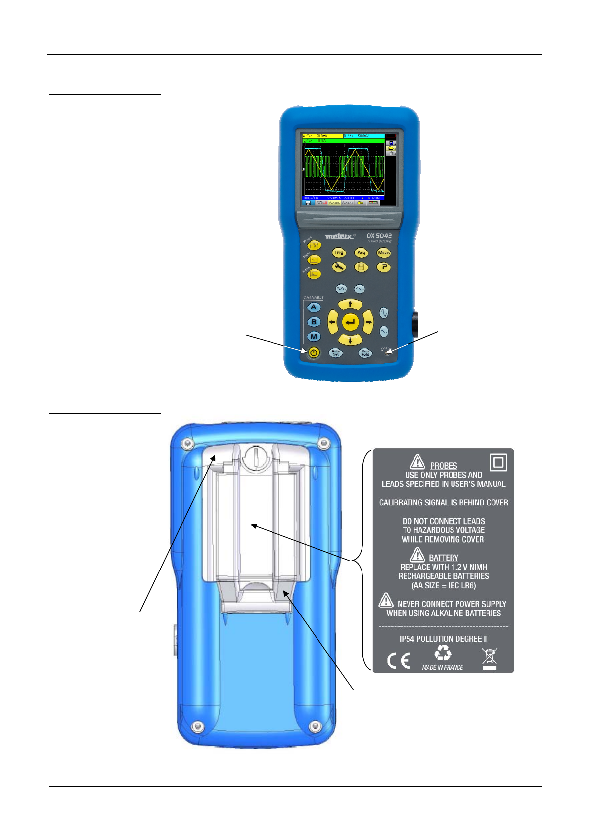
•The instrument must not be used other than to adjust the sensors, if the
battery housing cover is absent, damaged or incorrectly positioned.
definition of
installation
categories
Overvoltage category ll is for equipment intended to be supplied from the
building wiring. It applies both to plug-connected equipment and to
permanently connected equipment. E.g.: Measurements on the network circuits
of household appliances, portable tools and other similar appliances.
Overvoltage category lll is for equipment intended to form part of a building
wiring installation. Such equipment includes socket outlets, fuse panels, and
some mains installation control equipment. E.g. Measurements on distribution
panels (including secondary meters), circuit breakers, cabling including cables,
busbars, junction boxes, disconnecting switches, power outlets in the fixed
installation, and industrial appliances and other equipment, such as motors
permanently connected to the fixed installation
Overvoltage category lV is for equipment installed at or near the origin of
the electrical supply to a building, between the building entrance and the
main distribution board. Such equipment may include electricity tariff meters
and primary overcurrent protection devices. E.g.: Measurements on systems
installed before the main fuse or the circuit breaker of the building's installation.
Symbols used
I - 4 HandScope
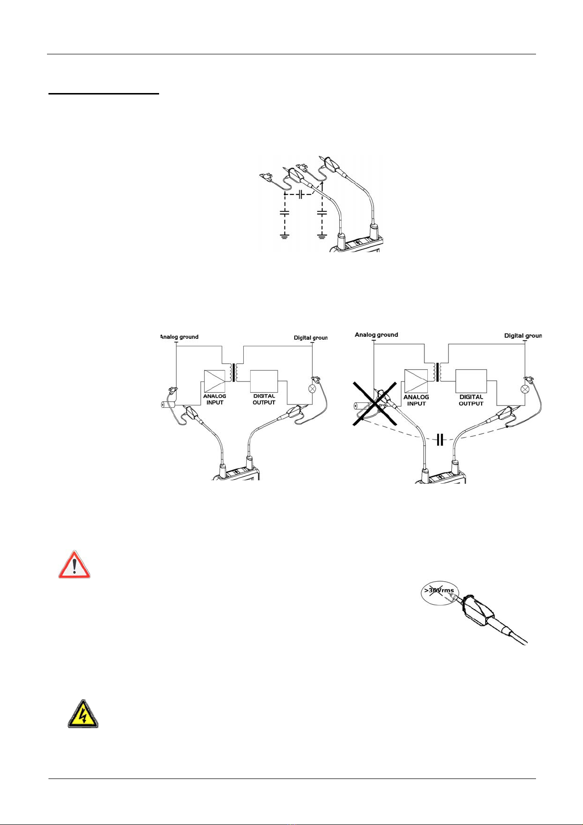
Risk of electric shocks: input connection and disconnection instructions. Always
connect the sensors or adapters to the instrument before connecting them to th
e
measuring points. Always disconnect the sensors or cables from the
measurement points before disconnecting them from the instrument. These
instructions apply before cleaning the instrument and before opening the battery
housing cover and the sensor calibration outputs.
Warning: Risk of danger. The operator undertakes to consult the instructions
each time this danger symbol is encountered.
Double insulation
Earth
In the European Union, this product is the subject of selective waste sorting for
the recycling of electric and electronic equipment in compliance with the
Directive WEEE 2002/96/CE: this equipment must not be considered as
household waste. The spent batteries and accumulators must not be treated
as household waste. Return them to the appropriate collection point for
recycling.
This CE marking indicates compliance with the European "Low Voltage" and
"Electromagnetic compatibility" directives (73/23/EEC and 89/336/EEC).
This product or this packaging is recyclable.

General
General (cont’d)
Warranty
This equipment has a 3-year warranty for faulty manufacture or materials
s per our sales terms and conditions.
a
During this period the appliance may only be repaired by the manufacturer.
The manufacturer reserves the right to proceed either with the repair, or
with the exchange of all or part of the appliance. In the event of a return to
he manufacturer, the shipping cost is paid by the customer.
t
The warranty will not apply in the event of:
•improper use of the equipment or use of the equipment with
incompatible equipment
•a modification to the equipment without an explicit authorisation from the
manufacturer's technical services
•intervention on the equipment by a person not approved by the
manufacturer
•adaptation to a specific application that was not part of the definition of
the equipment or the instructions for use
•shocks, falls or flooding.
Maintenance and
metrology checks
As for all measurement or test instruments, regular checking is necessary.
We recommend annual check of this instruments.
For checks, calibration, please return the device to your reseller.
Unpacking
re-packing
The equipment has been checked mechanically and electrically before
being shipped.
On receipt, make a rapid check in order to detect any damage during
transport. If there is damage, please contact our sales department as soon
as possible and transmit the legal reservations to the transporter.
In the case of re-shipping, preferably use the original packaging.
Repairs
under warranty and
outside the warranty
For repairs outside continental France, both with and without warranty,
return the appliance to your local Chauvin Arnoux branch or to your reseller.
Cleaning
•Disconnect the sensors or measurement cables.
•Power off the appliance.
•Clean with a damp cloth and soap.
•Never use abrasive products or solvents.
•Let the appliance dry before further use.
HandScope I - 5

General
Update of the instrument'sfirmware
•Log on to the site http://www.chauvin-arnoux.com
•In the "Support" section, select "Download Center".
•Download the "firmware" corresponding to the model you have
purchased.
•Also download the firmware installation instructions.
•Consult this installation note to update your instrument.
Integrated Help function
The oscilloscope has an integrated help function, designed to provide help
on the use of all the tabs on the main and secondary menus.
To consult the help function, press this key. Press it again to exit the help
menu.
To view the integrated help in other languages, open the Tools menu and
select the desired language.
I - 6 HandScope

Description of the instrument
Presentation The particularity of these oscilloscopes is that they group 3instruments in
one:
Harmonic
analyser
Digital
oscilloscope
Multimeter
OX 5022
OX 504
2
•a laboratory digital oscilloscope for the analysis of electronic and
electrotechnical signals,
•a 2-channel, 8000-count multimeter,
•a harmonic analyser, for the simultaneous decomposition
of 2 signals with their fundamental and their first 31 harmonics.
The instrument operates at a constant acquisition depth of 2,500 points.
An LCD TFT screen is used to view the applied signals along with all the
setting parameters.
The main command functions are accessible using the keys on the front
panel.
A graphic interface is used to:
- adjust the parameters related to the selected button,
- navigate using a horizontal main menu showing the current settings and
vertical sub-menus.
Power supply
The oscilloscope is delivered with:
•one external power supply ÆVoltage: 12 VDC
Power: 1.25 A
Polarity:
•6 rechargeable ÆNi-MH (1.2 V, 2700 mAh) accumulator batteries.
*
When the external power supply is connected, this power source is preferred
for the instrument's operation. Thus the accumulators are only used when
there is no external power supply.
With the external power supply you can use your oscilloscope even if
the batteries are flat, defective or even absent.
HandScope II - 7

Description of the instrument
Description of the instrument (cont’d)
Batteries
A "battery empty" indicator appears on the screen when the accumulator-
battery charge level is insufficient and a new power source is needed
quickly:
•connect the external power supply or
•change the batteries.
If the external power supplied is not connected when the level becomes
critical, an alarm message "Battery level is critical, the appliance is
about to power off" precedes the automatic shutdown of the instrument.
Charge The batteries are charged when the oscilloscope is powered off but
connected to the external power supply.
During the fast charge of the batteries, the front-panel LED is on.
It flashes in the following situations:
•pre-charge of very flat batteries
•temperature too low or too high
•batteries damaged.
When the charge is complete the LED switches off. The batteries must be
replaced with Ni-MH rechargeable batteries. Battery charge life is
guaranteed for same-capacity batteries (in mAh) as those shipped with the
oscilloscope.
*It is possible, but not recommended, to use standard alkaline batteries
(AA type) to replace the accumulators, but in this case be careful:
•not to connect the external power supply because when the
instrument is switched off the charge mechanism is activated which
can lead to destruction of the batteries and damage to the
instrument;
•not to leave the batteries in the instrument for too long to avoid
any problems caused by leakage from the batteries.
Access If necessary, the batteries(1) are accessible from the rear panel of the
oscilloscope after turning the "quarter turn" (2) lock anti-clockwise; use a
coin (3):
II - 8 HandScope

Description of the instrument
Description of the instrument (cont’d)
Channel insulation
The two oscilloscope input channels are insulated from each other and from
the earth and the mains power supply block. This insulation is double or
reinforced in compliance with the safety standards
IEC 61010-1 and IEC 61010-2-030.
This makes it possible to make measurements on installations or systems
connected to the electricity supply network for voltages of up to 600 V in
CAT III. The common mode authorised between the two channels is 600 V
in CAT III.
Thus the operator, the test systems and the environment are completely
protected at all times.
Any voltage (even dangerous) on one channel will not be present on the
other channel. The low points of the inputs are completely insulated, so there
is no possibility of the low points looping (which can be dangerous and highly
destructive).
The oscilloscope insulation is as shown in the diagram below:
*The use of accessories with a voltage and/or category lower than 600 V
CAT III reduces the operating range to the lower voltages and/or
categories.
Your oscilloscope is rated 600 V CAT III; at least 600 V CAT III
accessories must be used. The accessories shipped with the instrument
allow this.
HandScope II - 9

Description of the instrument
Description of the instrument (cont’d)
OX 5022 & OX 5042
Front panel
Battery charge LED
On / Off key
Back face Marking
The removable stand makes it possible
to keep the instrument at an angle of 30 °
in relation to the horizontal.
Battery cover
II - 10 HandScope

Description of the instrument
Description of the instrument (cont’d)
Measurement
terminals
Marking
External
power
supply
t
Input
Channel "A" Input
Channel "B"
Side
Optical
communicator
HandScope II - 11

Description of the instrument
Description of the instrument (cont’d)
Advice for use of
the sensors
Distribution of stray capacitors:
It is imperative, considering the stray capacitances, to correctly connect the
reference conductors for each sensor. The conductors should preferably be
connected to the cold points to avoid the transmission of noise by the stray
capacitance between modes.
Connection of the
reference
conductors to the
sensor
The noise of the digital ground (earth) is sent to the analogue input by the
stray capacitance
Reminder In order to prevent electric shocks or possible fires:
Never use accessories on which the casing
is accessible if it has a voltage of > 30 Vrms
compared to the earth.
This precaution is necessary for example for sensors with an
accessible metal BNC. The accessories shipped with the instrument
are compliant.
Reminder See p. 4 Input connection and disconnection instructions.
II - 12 HandScope

Description of the instrument
Description of the instrument (cont’d)
Sensor calibration The calibration output (3 Vpp, 1 kHz) for the sensors is underneath the
battery cover (see p. 10).
To obtain optimum response, the sensor's low frequency compensation must
be adjusted. To carry out this adjustment, the two channels of your
oscilloscope must be disconnected from the measured circuits before
opening the battery housing cover.
Select the DC coupling for the channel to which the sensor is connected and
run an autoset (icon opposite) to carry out pre-setting. Adjust the sensitivity
and the vertical offset of the channel so that the signal fills the screen, and
adjust the time base to 200 µs to view a signal period on the screen. Turn the
BNC base of the sensor in order to access the sensor adjustment screw:
Connect the sensor to be
adjusted to the calibration
output under the battery housing
cover, as shown opposite.
In the example opposite the
sensor is over-compensated:
an overshoot occurs.
Turn the screw in either direction
until the signal is horizontal and
looks like the screen shown
opposite. Your sensor is now
calibrated, so you can turn the
BNC base again to close access
to the adjustment screw.
*Replace the battery cover in order to use your instrument in optimum safety
conditions.
HandScope II - 13

Description of the instrument
Description of the instrument (cont’d)
Front panel
(description) The main functions of the instrument are accessed from the front panel.
1 on / off key
The instrument is switched on by a short press on the key shown opposite. It
is switched off by a long press (a shutdown message appears and a beep
sounds).
3 "operating mode"
keys
Pressing on one of these three keys selects the instrument's operating
mode:
•"oscilloscope ", see p. 15.
•"multimeter" see p. 48.
•"harmonic analyser" see p. 57.
5 navigation keys
This block of keys is used to move around the menus and in the dialogue
boxes; it is also used to move graphic objects (cursor, trigger, memory
position...) through the menus.
•Action of the horizontal keys:
- Horizontal movement through the main menus
- Adjustment of values in the secondary menus
- Horizontal movement in a dialogue box
•Action of the vertical keys:
- Vertical movement and automatic selection in the secondary
menus
- Adjustment of values in the main menus
- Vertical movement in a dialogue box
•Action of the central "Enter" key:
- Opens a dialogue window from a main menu or a secondary
menu
- Validation of the items in a dialogue window
II - 14 HandScope

Oscilloscope Mode - The keys
Oscilloscope Mode
The keys
Pressing this key selects the "Oscilloscope" mode.
6 "Menu" keys
Trigger displays the main "Trigger" menu, see p. 31.
Acquisition displays the main "Acquisition" menu, see p. 36.
Tools displays the main "Tools" menu, see p. 46.
Measurement displays the main "Measurement/Cursor" menu, see p. 40.
Memory displays the main "Memory" menu, see p. 43.
Help displays the "Help" window, see p. 47.
3 Channel A, B,
and Math or Memory keys
Channel
Channel
- A simple press selects channel A (or B) and shows the corresponding menu.
- Pressing twice deselects the channel.
Function
- A single press selects channel M (Math) and shows the corresponding menu.
- Pressing twice deselects the channel.
*For the M (memory) channel, pressing twice invalidates the channel. Pressing
once again selects the Math channel, the memory is lost and must be
reloaded.
2 "Time base" keys
increases the time base for acquisition up to 200 s.
decreases the time base for acquisition down to 25 ns.
2 "sensitivity" keys
decreases the vertical sensitivity of the last selected channel down to 5 mV.
increases the vertical sensitivity of the last selected channel up to 200 V.
*For the M channel, the "sensitivity" key varies the amplitude factor but only if
a math channel is validated.
2 functional keys
performs an automatic adjustment on channels A and B. The success of each
vertical autoset conditions the activation of the channel.
starts or stops an acquisition.
HandScope III - 15

Oscilloscope Mode - Display
Oscilloscope Mode
Display
Display
1. Channel
data
a) "Main channel"
area
The direct data from channels A and B are displayed in this window:
•Channel identification
•Channel coupling
•Filter
•Channel sensitivity
•Channel unit
(∗) If no measurement is selected, if measurement is impossible or if the
channel is not validated, the measurement will be replaced
by dashes.
5.
Secondary
menu area
(∗) 1.
Channel data
area
Battery
info. area
2. Area
for main
display
3. Time data
area
4. Main menu area
(∗)
Channel
identification Unit
AC, DC, GND
coupling
Filter: no icon Æno filter
1.5 MHz filter
5 kHz filter
Sensitivity
III - 16 HandScope

Oscilloscope Mode - Display
Oscilloscope Mode
Display (cont’d)
b) "Automatic
measurement"
area
The selected automatic measurements are shown in this window. 1 or 2
measurements per channel can be selected.
c ) "Math" area
Automatic
measurement
of channel A
Automatic
measurement
of channel B
Automatic
measurement
of channel B
Automatic
measurement
of channel A
or "Memory" area
The "M" channel data is shown in this window. This channel can contain a
"Math" or a "Memory" function.
If the "M" channel shows a "Math" function, the following data is shown:
•Channel identification
•Sensiitivity
•Unit
•Automatic measurements
If the "M" channel shows a "Memory" function, the following data is shown:
•Channel identification
•Sensitivity
Channel
indicator
Automatic
measurement 1
Automatic
measurement
Unit
Violet background in "M"
channel shows a Math
function
Coupling Filter
Sensiitivity
Green background if "M"
channel shows a Memory
function
•Coupling
•Filter
•Unit
•Automatic measurements
HandScope III - 17

Oscilloscope Mode - Display
Oscilloscope Mode
Display (cont’d)
d ) "Cursor
measurement"
zone
Delta t
measurement
Delta V
measurement
Cursor 1
voltage
Cursor 2
voltage
The measurements by cursor are shown in this window. The background
colour is identical to that for the channel to which the cursors are attached.
It indicates:
•the horizontal difference (dt) and vertical difference (dv) between the
2 cursors,
•the voltage measurement of the cursors.
2. Main display
Selection of a
zoom zone
Reticle/crosshair
Cursor 1 Position
indicator for manual
measurement cursors
Cursor 2 Position indicator
for manual measurement
cursors
Vertical Trigger
level indicator
Automatic cursors
attached to
measurement 1
Indication of the
channel and its
vertical level
Horizontal trigger
position
Displayed
III - 18 HandScope

Oscilloscope Mode - Display
Oscilloscope Mode
Display (cont’d)
3. Time data
This window is split into two groups:
•a time data group
- time base
- sampling frequency
•a trigger data group
- triggering mode
- trigger type
- trigger source
- trigger status: RUN, READY, STOP.
4. Main menu area
Main menu: displays the oscilloscope configuration
5. Secondary menu
area
Sampling frequency Trigger type Trigger
status
Time base Triggering mode Trigger
Source
Secondary menu: gives access to various
parameter settings selected from the main menu.
HandScope III - 19

Oscilloscope Mode - The Menus
Oscilloscope Mode
The Menus
Display
Organization The menus have two elements:
- a horizontal menu, called "main", located at the bottom of the screen;
- a vertical menu, called "secondary" located to the right of the screen
Main menu
When a tab is selected in the menus, its background turns yellow. When a
setting is not available in the current mode, it is greyed out in the main menu
and cannot be selected.
Secondary menu Each tab of the main menu is associated with a secondary menu
used to view the different possible settings for the parameter in
question.
Navigation
Classical
navigation
These keys are use to navigate in the main menu.
These keys are used to:
- navigate in the secondary menu,
- set a vertical parameter (see §. Vertical settings)
III - 20 HandScope
This manual suits for next models
1
Table of contents
Other Metrix Test Equipment manuals

Metrix
Metrix MX2040 User manual

Metrix
Metrix OX 832 User manual

Metrix
Metrix MX 604 User manual

Metrix
Metrix MX 67 User manual

Metrix
Metrix MTX 3252e-C User manual

Metrix
Metrix MX 407 User manual

Metrix
Metrix OX 6062-II User manual

Metrix
Metrix MX 407 User manual

Metrix
Metrix GX-1030 User manual

Metrix
Metrix MTX 3352 User manual

Metrix
Metrix HI-903 User manual

Metrix
Metrix OX 530 User manual

Metrix
Metrix CX 1651 User manual

Metrix
Metrix TCX01 User manual

Metrix
Metrix MX 435D User manual

Metrix
Metrix MX 535 User manual

Metrix
Metrix ScopiX IV Series User manual

Metrix
Metrix CX 1651 User manual

Metrix
Metrix MX 535 User manual

Metrix
Metrix DOX 2 Series User manual