Sonotec SONO-PR 200 User manual
Operating Manual
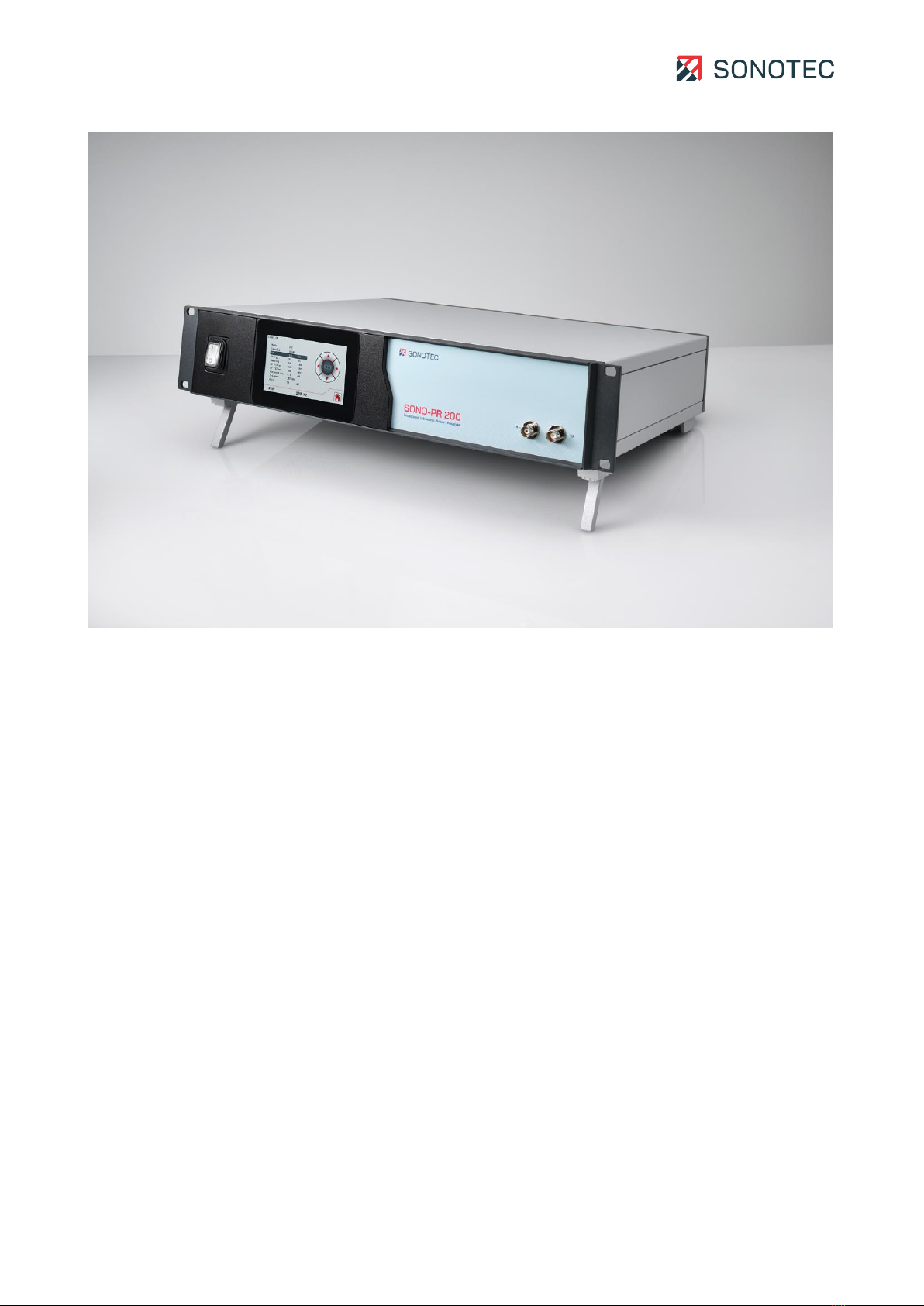
SONO-PR 200
Broadband ultrasonic pulser-receiver for nondestructive testing
Translation of the German Original
Revision: 2.0 | 2022-10-14

Operating Manual | Content
SONO-PR 200
2 / 47
Revision: 2.0 | 2022-10-14
Content
1Introduction...................................................................................................................... 4
1.1 Notes on this documentation.........................................................................................4
1.2 Representations in this documentation ........................................................................4
1.3 Identification of warning instructions............................................................................5
2Safety instructions ...........................................................................................................6
2.1 Introduction......................................................................................................................6
2.2 Basic hazards...................................................................................................................7
2.3 Personnel and qualifications ..........................................................................................8
2.4 Safety-conscious working practices.............................................................................9
2.5 Use of the product ..........................................................................................................9
2.6 Modifications and alterations.........................................................................................9
3Description of the device ............................................................................................... 11
3.1 Intended use ...................................................................................................................11
3.2 Prohibited use.................................................................................................................11
3.3 Scope of delivery........................................................................................................... 12
3.4 Device labeling ..............................................................................................................13
3.5 Front side of the device................................................................................................14
3.6 Back side of the device ................................................................................................15
3.7 Touch screen .................................................................................................................16
3.7.1 Main menu .........................................................................................................16
3.7.2 Settings ..............................................................................................................19
3.7.3 Setups ............................................................................................................... 20
3.7.4 Brightness..........................................................................................................21
3.8 RS-232 interface ...........................................................................................................22
3.8.1 RS-232 settings ................................................................................................22
3.8.2 Commands.........................................................................................................22
3.8.3 Queries .............................................................................................................. 24
3.8.4 Parameter dependencies................................................................................ 26
4Preparing a work order...................................................................................................27
4.1 Positioning......................................................................................................................27
4.2 Connecting external devices .......................................................................................28
4.3 Adjusting the brightness of the touch screen........................................................... 30
4.4 Setting the signal trigger ............................................................................................. 30
4.5 Setting the operation mode ........................................................................................ 32
4.6 Setting the transmitter pulse type.............................................................................. 33
5Performing a work order................................................................................................ 34
5.1 Connecting a probe (SONOTEC probes)................................................................... 34
5.2 Setting up parameters ................................................................................................. 36
5.3 Saving settings ..............................................................................................................37

Operating Manual | Content
SONO-PR 200
3 / 47
Revision: 2.0 | 2022-10-14
5.4 Overwriting an existing setup ..................................................................................... 38
5.5 Loading settings........................................................................................................... 39
6Maintaining the system ................................................................................................. 40
6.1 Replacing fuses ............................................................................................................ 40
6.2 Cleaning..........................................................................................................................41
6.3 Maintenance ..................................................................................................................41
7Technical data ............................................................................................................... 42
8Disposal.......................................................................................................................... 45
9Warranty ........................................................................................................................ 46
10 Manufacturer information ............................................................................................. 47
Operating Manual | 1 Introduction
SONO-PR 200
4 / 47
Revision: 2.0 | 2022-10-14
1Introduction
This section is intended to explain function, structure and representations of the document
to simplify handling of the document.
1.1 Notes on this documentation
Purpose
This document constitutes an integral part of the product and contains important advice on
safe operation as well as all information on intended and efficient use. Thus, any person
using the product must have read and understood this document.
Accessibility
The staff working with this product must have constant access to this document to prevent
handling errors and guarantee trouble-free operation.
Up-to-dateness
Every effort has been made to ensure that the information contained in this document is
complete and correct at the time of release. This document describes all units and functions
known of at the current point of time.
1.2 Representations in this documentation
Illustrations
Illustrations used in this document do not always contain all details or special cases. They
only represent the relevant information.
Tips
Tips are marked as follows:
Tips describe specific information or particular features that might not be evident, even
for experienced users. The neglect of a tip poses no direct safety risk. However, it can
lead to workflow disruptions.
General icons
The following general icons are used for visual emphasis:
Icon
Function
Indicates a link to external content.

Operating Manual | 1 Introduction
SONO-PR 200
5 / 47
Revision: 2.0 | 2022-10-14
1.3 Identification of warning instructions
Classes of danger, signal words and colors
This document contains warnings regarding hazards of different classifications. These
classes are characterized by signal words and colors. They include the following:
DANGER
Warns of immediate danger, which, if ignored, may lead to death or serious injury.
WARNING
Warns of possible immediate danger, which, if ignored, may lead to lasting damage to
health and/or property - including financial losses due to operational impairment.
ATTENTION
Warns of dangers, which, if ignored, may lead to damage to property –including damage
to property due to operational interruptions.

Operating Manual | 2 Safety instructions
SONO-PR 200
6 / 47
Revision: 2.0 | 2022-10-14
2Safety instructions
This section contains safety information relating to the protection of persons as well as safe
and fault-free operation. All user groups of the product must be aware of and follow these
safety provisions.
2.1 Introduction
Reliable and safe operation of the product depends on the careful handling and execution of
operational and setting tasks.
Ignoring these safety instructions and warning information may lead to serious injury with
lasting health consequences for personnel as well as damage or destruction of product
components.
During handling of the product, please observe all safety instructions and warning
information in all parts of this user documentation as well as the related codes of practice.
Ensure that all those working with the product are also aware of these instructions.
Generally applicable safety regulations (such as accident prevention and environmental
protection regulations, etc.) must also be observed.

Operating Manual | 2 Safety instructions
SONO-PR 200
7 / 47
Revision: 2.0 | 2022-10-14
2.2 Basic hazards
Definition
Basic hazards are residual risks that remain even with safety-conscious intended use.
State of the art
The product meets the current state of the art and applicable safety rules. All components
of the product are tested thoroughly before they leave the factory and are delivered in a
condition for safe operation.
WARNING
Danger of injury!
Improper use of the device may lead to injuries.
•Do not open the device.
•Protect the device against extreme heat (excessive sunlight, immediate vicinity of
open fire or heating devices) during operation and storage.
•Avoid strong impacts that could damage the device and/or its components.
ATTENTION
Possible damage of the device display!
Improper use may damage the device display.
•Do not use scratching or sharp objects to operate the device by touch screen.
Commercially available pens for touch screens are suitable.

Operating Manual | 2 Safety instructions
SONO-PR 200
8 / 47
Revision: 2.0 | 2022-10-14
2.3 Personnel and qualifications
Basic requirements
The product must only be used by operators that have completely read and understood the
safety instructions and all documents of the user documentation.
Personnel undergoing training or instructions or persons taking part in general vocational
training programs may only operate the device under the continuous supervision of
operating or technical personnel.
Responsibility of the operating company
Regarding the personnel authorized and/or trained by the operating company, the operating
company carries the following responsibilities:
•The necessary training and instruction of personnel must be guaranteed.
•All personnel's competences and responsibilities must be clearly stated and
documented.
•All user information on the product (operating manual, user documentation etc.) must
be kept in the immediate vicinity of the product and must be accessible at all times.
Requirements for ultrasonic testing
Operators must have thorough expertise, skills and experience to avoid errors that may lead
to unforeseeable consequences. SONOTEC recommends that operators should undergo
professional ultrasonic testing training according to applicable regulations.
Nondestructive ultrasonic testing may only be carried out when the following (minimum)
conditions are met:
•Selection of a suitable probe
•Complete and correct configuration of the device parameters
•Selection of a suitable testing method
•Correct interpretation of the generated echoes
Configuring the parameters and evaluating the test results require thorough knowledge of
the dissemination in space and time of ultrasound in a range of materials, the behavior of
ultrasonic waves at limit surfaces –such as material flaws or transition zones –and the
capabilities of ultrasonic equipment to optimally display echo patterns.

Operating Manual | 2 Safety instructions
SONO-PR 200
9 / 47
Revision: 2.0 | 2022-10-14
2.4 Safety-conscious working practices
Accident prevention and environmental protection
In addition to the instructions in this operating manual, please mind the generally applicable
legal and other regulations on accident prevention and environmental protection.
This may include, for example:
•Handling of hazardous materials
•Wearing the required and mandatory personal protective clothing and safety
equipment
•Observing of and complying with all national and regional industrial safety regulations
•Observing of and complying with all internal working, operating and safety regulations
2.5 Use of the product
General use
Improper use of the product may lead to injuries of operating personnel and/or product
damage. Damaged components may affect or distort the measurement result quality.
•During use, charging and storage, protect the device against extreme, unusual heat
(excessive sunlight, storage in heated cars or immediate vicinity of open fire or heating
devices). It is critical to stay within the temperature ranges given in the technical
specification.
•Do not use the product and its accessories if they display functional errors and/or
visible damage.
•Only connect the product to approved equipment received from SONOTEC GmbH or
its sales partners.
•Handle the product with care and protect it against major shocks.
•Do not use the product within strong electromagnetic fields.
•Do not use scratching or sharp objects to operate the touchscreen. Apart from
operation by finger touch, commercially available touchscreen pens or touchscreen
gloves are suitable.
Functionality of safety and protective devices
The full functionality of all safety and protective devices must be ensured at all times. All
equipment must regularly be checked for full functionality and completeness.
This applies to the device as single component as well as an overall system into which the
device is integrated as a component.
2.6 Modifications and alterations
No modifications on the product and/or accessories
The product and/or its accessories must not be opened or disassembled. The product does
not contain any components to be cleaned, maintained or repaired by operators.

Operating Manual | 2 Safety instructions
SONO-PR 200
10 / 47
Revision: 2.0 | 2022-10-14
Unauthorized modifications of the product and/or its accessories are prohibited and lead to
exclusion of liability by the manufacturer for resulting damage and consequences.
Spare parts and accessories
Spare parts and accessories must comply with the technical requirements specified by
SONOTEC GmbH and its suppliers. Whenever original parts are used, compliance is given.
No alterations to the software
Do not alter the supplied software or commission software alterations to third parties. The
software may not be disassembled, decrypted or decompiled in full or in part.

Operating Manual | 3 Description of the device
SONO-PR 200
11 / 47
Revision: 2.0 | 2022-10-14
3Description of the device
This section describes use, connections and operating elements of the SONO-PR 200.
3.1 Intended use
The SONO-PR 200 is a high-performance broadband pulser-receiver and intended for the
following applications:
•Nondestructive measurement/examination of wall thickness
•Nondestructive material testing
•Probe specification in R&D
•Immersion and squirter applications
•Acoustic microscopy
•Integration into automated testing systems
3.2 Prohibited use
Any use not approved by SONOTEC GmbH is prohibited and may lead to injury or damage to
property.
SONOTEC GmbH accepts no liability for damage caused by prohibited use of the product.
Prohibited are in particular:
•Use of equipment and/or accessories with visible damage
•Use in wet rooms
•Use in potentially explosive environments
•Use in environmental conditions that do not adhere to the stipulated requirements
•Unauthorized modifications of the equipment, the software and/or accessories
•Use of unauthorized spare parts and/or unauthorized accessories
Operating or using the product incorrectly and/or not in the sense of its intended use may
lead to risk of death and personal injury.

Operating Manual | 3 Description of the device
SONO-PR 200
12 / 47
Revision: 2.0 | 2022-10-14
3.3 Scope of delivery
The following components are part of the scope of delivery:
•SONO-PR 200 (configuration depending on the specific order)
•Power cord
•Operating Manual
The following configurations are available:
Designation
Article number
SONO-PR 200 Spike Pulser –Rack mount
200 09 0001
SONO-PR 200 Spike Pulser –Desktop
200 09 0009
SONO-PR 200 Combi Sender –Desktop
200 09 0015
SONO-PR 200 Combi Sender –Rack mount
200 09 0016
Optional
Designation
Article number
SONO-AMP Set (low noise pre-amplifier including power coupler)
700 01 0398
Operating Manual | 3 Description of the device
SONO-PR 200
13 / 47
Revision: 2.0 | 2022-10-14
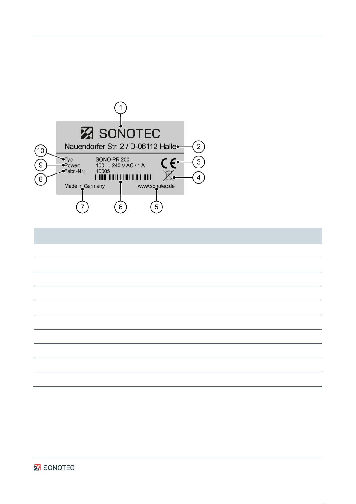
3.4 Device labeling
Identification plate
The identification plate is located on the back side of the device. Please keep the data on
the identification plate ready whenever you contact customer service.
Figure 1: Identification plate with its components
Nr.
Identification
1
Name of manufacturer
2
Manufacturer’s address
3
CE marking
4
Disposal symbol (see "8 Disposal", page 45)
5
Manufacturer's website
6
Bar code
7
Country of origin
8
Serial number
9
Power rating
10
Device designation
Operating Manual | 3 Description of the device
SONO-PR 200
14 / 47
Revision: 2.0 | 2022-10-14
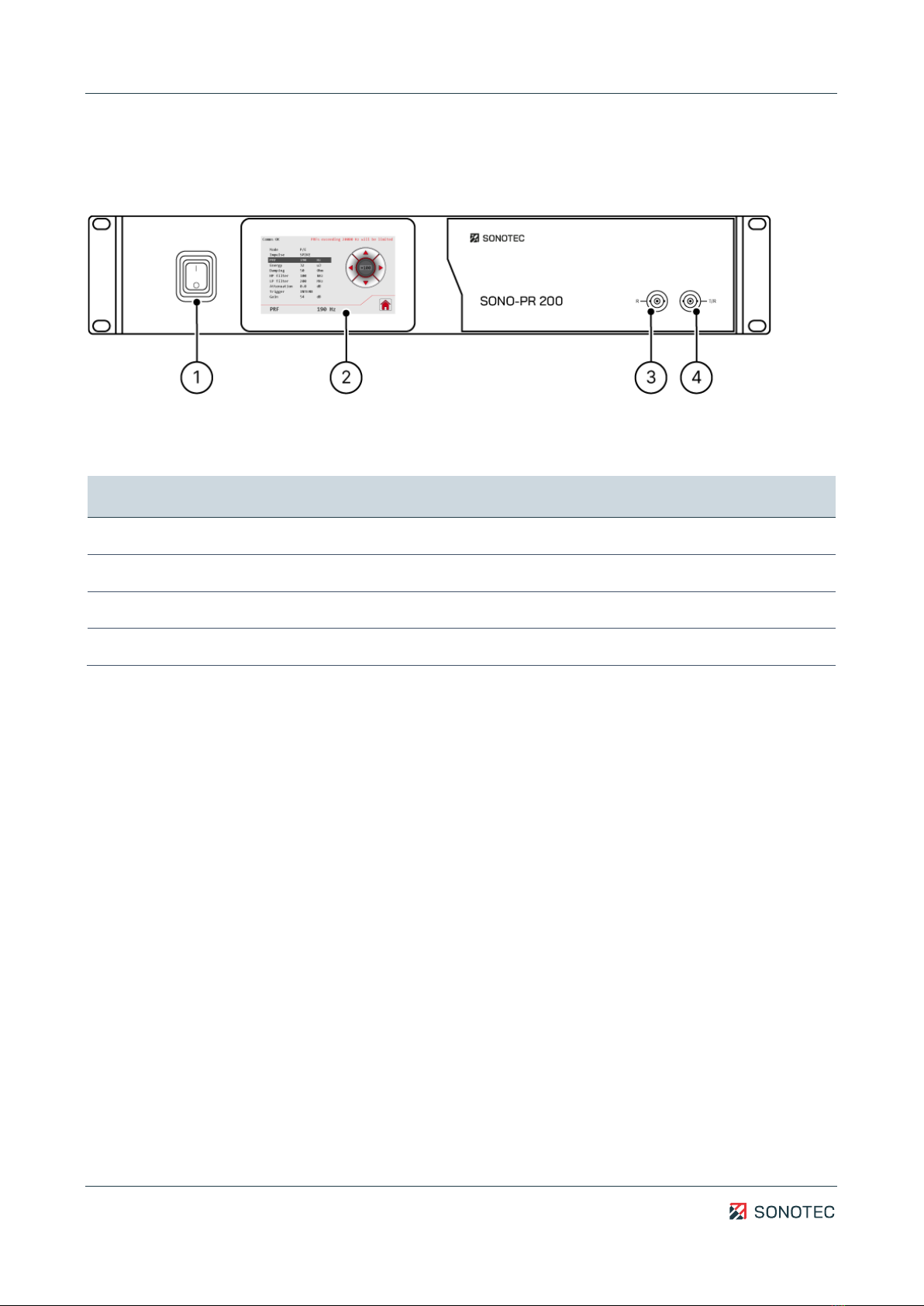
3.5 Front side of the device
Structure
Figure 2: Front side of the device with its components
Description
No.
Component
1
On/off switch
2
Touch screen (see "3.7 Touch screen", page 16)
3
Probe output (receiver)
4
Probe output (transmitter/receiver)

Operating Manual | 3 Description of the device
SONO-PR 200
15 / 47
Revision: 2.0 | 2022-10-14
3.6 Back side of the device
Structure
Figure 3: Back side of the device with connections
Description
No.
Component
1
Analog HF Out
•Analog high frequency signal output
•Type: BNC connector
2
RS-232 interface
•Connector for computer interface
•Type: 9 pin D-sub male
3
Trigger In
•Trigger signal input
•Type: BNC connector
4
Trigger Out
•Trigger signal output
•Type: BNC connector
5
Digital I/O
•Digital inputs and outputs
•Type: Phoenix MCV 1,5/ 8-GF-3,81
6
Mains voltage with fuses
•110/220 VAC, 1 A, 50/60 Hz
•Type: C14 male
•Fuses: 2, replaceable, type T1A (1 A, 250 V)
Operating Manual | 3 Description of the device
SONO-PR 200
16 / 47
Revision: 2.0 | 2022-10-14
3.7 Touch screen
The touch screen is used to set the parameters of SONO-PR 200. This section describes the
screens individual of the touch screen.
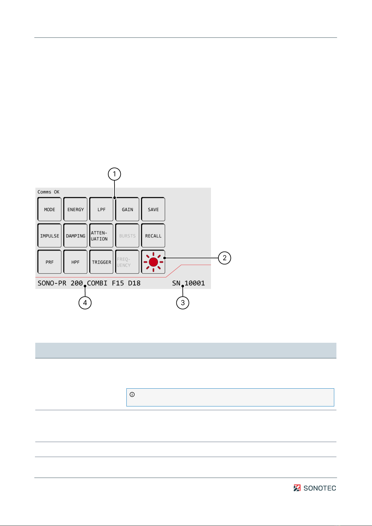
3.7.1 Main menu
Function
The “Main menu” screen contains a list of all configurable parameters as well as functions
for saving and loading settings.
Structure
Figure 4: “Main menu” screen with components
Description
No.
Type
Description/function
1
Parameter
Shows buttons for all parameters.
Tapping a parameter button opens the “Settings” screen for
customizing the respective parameter.
Parameter availability depends on the device configuration and/or
current device settings. Unavailable parameters will be grayed out.
Mode
Setting the operation mode:
P/E (Pulse/Echo)
T/R (Transmitter/Receiver)
Energy
Setting the energy output of the pulser output in the following steps:

Operating Manual | 3 Description of the device
SONO-PR 200
17 / 47
Revision: 2.0 | 2022-10-14
No.
Type
Description/function
1 | 2 | 4 | 8 | 16 | 32 μJ
Available for “SPIKE” pulse only.
Voltage
Setting the pulser output voltage:
•in “P/E” mode: 10 … 100 V (in 10 V increments)
•in “T/R” mode and 50 Ω impedance: 10 … 100 V (in 10 V
increments)
•in “T/R” mode and 1 kΩ impedance: 20 … 200 V (in 20 V
increments)
Available for “RECT” pulse only.
LPF
Setting the low-pass filter:
200 MHz | 100 MHz | 50 MHz | 20 MHz
Gain
Setting the receiver signal gain in the following steps:
26 | 40 | 54 dB
Save
Saving all current settings as a specific setup.
Opens the “Setups” screen.
Impulse
Setting the pulse type:
•RECT (unipolar-)
•RECT (unipolar+) (optional)
•RECT (bipolar) (optional)
•SPIKE (peak)
Damping
Setting the pulser output impedance in Ω.
Attenuation
Setting the receiver signal attenuation:
Range: 0 … 65.5 dB
Increment: 0.5 | 6 dB
Bursts
Setting the number of pulse repetitions:
Range: 1 … 10 impulses
Available for “RECT” pulse only.
Recall
Loading saved settings.
Opens the “Setups” screen.
PRF
Setting the pulse repetition frequency (frequency of generated pulses)
for internal signal trigger:
Range: 10 Hz … 20 kHz
Increment: 10 | 100 | 1000 Hz
HPF
Setting the high-pass filter.
100 kHz | 1 MHz | 3 MHz | 10 MHz

Operating Manual | 3 Description of the device
SONO-PR 200
18 / 47
Revision: 2.0 | 2022-10-14
No.
Type
Description/function
Trigger
Switching the signal triggering mode:
INTERN (internal trigger –PRF)
EXTERN (external trigger)
Frequency (Width)
Setting the pulse width:
Range: 63 … 1000 ns
Available for “RECT” pulse only.
2
Brightness
Adjusting screen brightness.
Opens the “Brightness” screen.
3
Serial number
Shows the device's serial number.
4
Device configuration
Shows the device name and configuration (Spike or Combi).
Automatic constraint of pulse repetition frequency (PRF)
When using the “RECT” pulse type, it will not be possible to simultaneously set
maximum values for “Voltage”, “Damping”, “Burst”, “Width” and “PRF”. Depending on the
particular settings, the software will automatically constraint the PRF. The maximum
permissible PRF for the current parameter settings is displayed the “Settings” screen.
Operating Manual | 3 Description of the device
SONO-PR 200
19 / 47
Revision: 2.0 | 2022-10-14
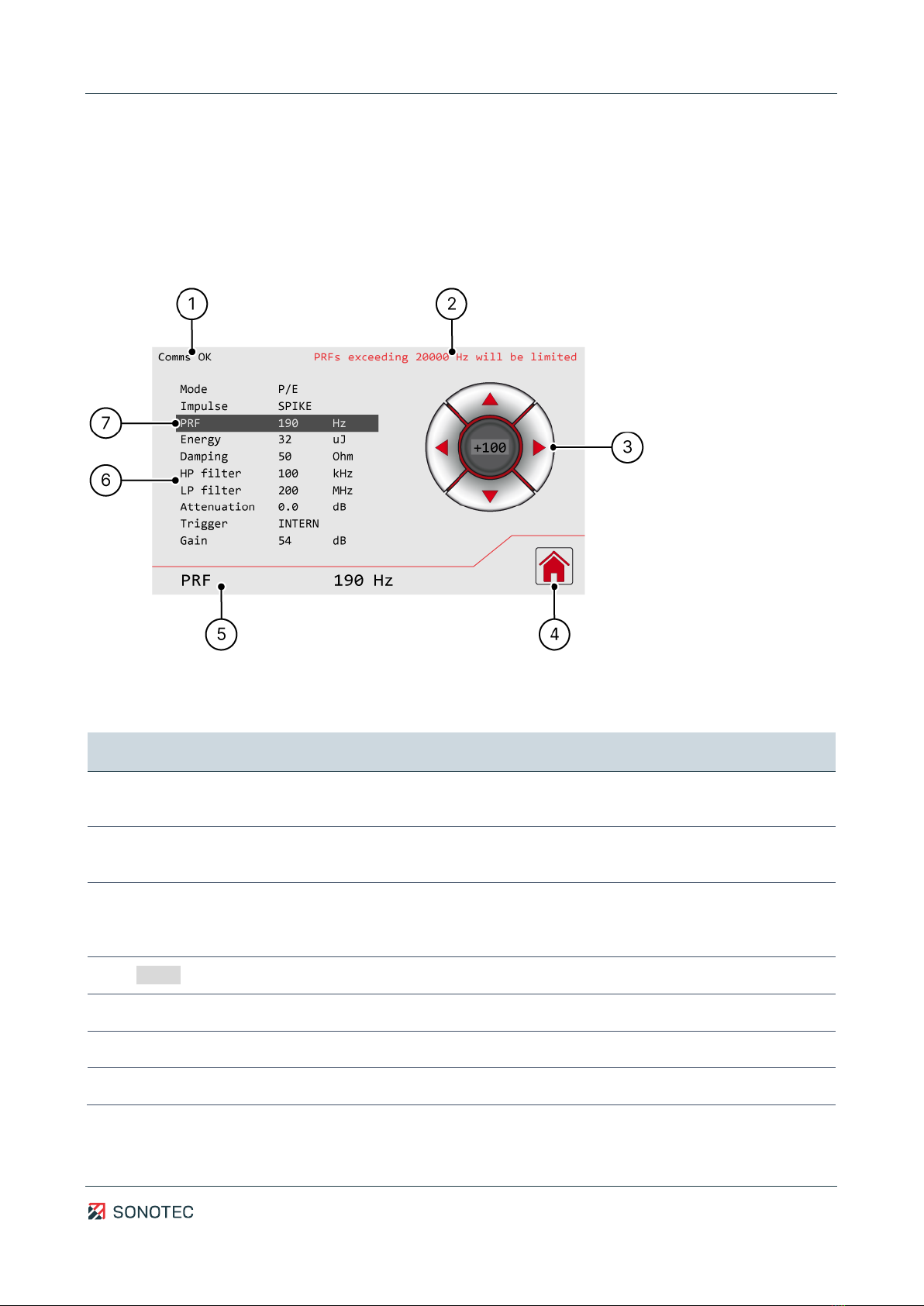
3.7.2 Settings
Function
The “Settings” screen is used to set parameter values.
Structure
Figure 5: “Settings“ screen with components
Description
No.
Type
Description/function
1
Device communication
status
•OK: Device communication okay
•NOK: Device communication faulty
2
PRF constraint
Shows the maximum permissible pulse repetition frequency (PRF) of
the current configuration.
3
Directional pad
•Top and bottom buttons: navigation between settings
•Left and right buttons: adjusting the selected parameter value
•Center button: setting the increments for PRF or attenuation
4
Home
Switching to the “Main menu” screen
5
Current setting
Shows the currently selected setting.
6
Parameter list
List of available settings with currently set values.
7
Current setting
Shows the currently selected setting.

Operating Manual | 3 Description of the device
SONO-PR 200
20 / 47
Revision: 2.0 | 2022-10-14
3.7.3 Setups
Function
In the “Setups” screen, all set parameters may be saved as one specific setup. In total, 15
setups may be saved. Existing setups may be overwritten with new settings.
Structure
Figure 6: “Setups”screen with components
Description
No.
Type
Description/function
1
Assigned setup
Setup with saved settings.
2
Available setup
Setup without saved settings.
3
Home
Switching to the “Main menu” screen
This manual suits for next models
4
Table of contents
Other Sonotec Test Equipment manuals

Sonotec
Sonotec Sonaphone Manual

Sonotec
Sonotec Sonaphone Manual

Sonotec
Sonotec SONASCREEN User manual

Sonotec
Sonotec SONAPHONE E User manual

Sonotec
Sonotec SONAPHONE E User manual

Sonotec
Sonotec Airborne Sound Sensor BS10 Operator's manual

Sonotec
Sonotec Sonaphone Pocket User manual

Sonotec
Sonotec Sonaphone Operator's manual

Sonotec
Sonotec Sonaphone User manual


