Sontay GS-S-CO-W User manual

UK Sales Tel: 0845 345 7253 International Tel: +44 1732 861225
Wall Mount Carbon Monoxide Sensor
Page 1 of 3
GS-S-CO-W
Issue: 5.0
Date Of Issue: 19/12/2011
© 2011 Sontay Limited. All rights reserved.
Features
Specification Product Codes
User selectable 0-10Vdc or 4-20mA output
Up to 5 year life time
Robust housing
Ranges:
GS-S-CO-W-K 0 to 100ppm
GS-S-CO-W-P 0 to 1000ppm
Output signals (jumper selectable):
0-10Vdc
4-20mA
Modbus RS485 19200bps, 15KV antistatic protection
Power supply:
Voltage output 24Vac/dc, ±10%
Current output 24Vdc only, ±10%
Consumption 2.8W
Sensor life 5 years, typical
Response time Within 60 seconds
Accuracy <1ppm @ 25°C
Stability ±5% (over 900 days)
Stabilization time 1 Hour
Environmental:
Operational:
Temp 0 to 50°C
RH 0 to 99% non-condensing
Storage:
Temp 10 to 50°C
RH 10 to 70% non-condensing
CE Conformity CE Marked
Housing dimensions:
Housing 100 x 80 x 50mm
Probe 69 x 26mm
Housing material ABS
Protection IP30
Country of origin China
GS-S-CO-W-K
Carbon Monoxide sensor, 0-100ppm selectable 0-
10Vdc or 4-20mA output
GS-S-CO-W-P
Carbon Monoxide sensor, 0-1000ppm selectable 0-
10Vdc or 4-20mA output
Please Note:
Current versions are NOT loop powered and will require a
common 0V connection.
Page 2 of 3
UK Sales Tel: 0845 345 7253 International Tel: +44 1732 861225
GS-S-CO-W
Issue: 5.0
Date Of Issue: 19/12/2011
© 2011 Sontay Limited. All rights reserved.
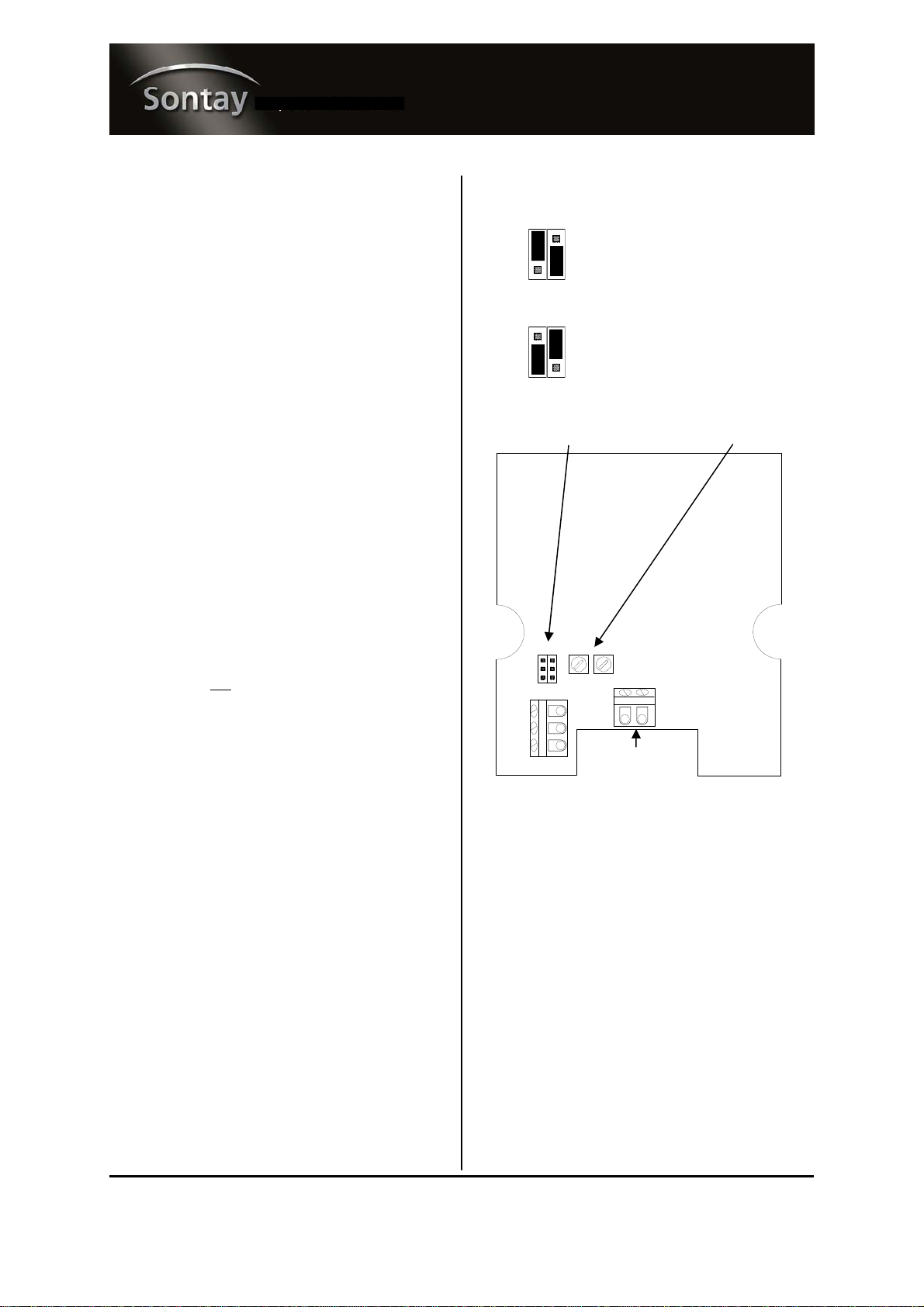
Technical Overview Jumper Settings
A user selectable 0-10Vdc, 4-20mA or optional Modbus
output is available with the GS-S-CO-W range. Using a
robust long life electrochemical Carbon Monoxide sensor,
the GS-CO-S-W is idea for many applications including
underground parking, loading bays and warehouses.
Installation
1. Select a location on a wall of the controlled space which
will give a representative sample of the prevailing room
condition.
Avoid sitting the sensor in direct sunlight, near
diffusers and steam sources.
2. Unscrew and remove the front panel from the base.
3. Using the base as a template mark the hole centres
(100mm) and fix to the wall with suitable screws. The
probe must be pointing downwards.
4. Feed cable through the knockout in the base of the
housing and terminate the cores at the terminal block.
Install wiring into terminal blocks as required.
5. Select output type, 0-10Vdc or 4-20mA the default is
0-10Vdc. Do not adjust the potentiometers W1 & W2,
as this will void warranty.
6. Ensure that the supply voltage is within the specified
tolerances.
7. Replace the front cover to the base plate, and tighten
thescrews.
8. Power the unit, pre-commissioning checks can be made
after 6 minutes. Full commissioning should not be
carried out for at least an hour.
9. It is recommended that screened cable be used and that
the screen should be earthed at the controller only. Care
should be taken not to lay control signal wiring in close
proximity to power or other cables which may produce
significant electromagnetic noise.
0-10Vdc
4-20mA
Connections
Terminals
1 24V (see below)
2 0V
3 Selectable output, 0-10Vdc or 4-20mA
7 A (TX+) RS 485
8 B (RX-) RS 485
Note:
Voltage output
This can be supplied with 24Vac/dc.
Current output
If using in current output mode, the sensor must only be
used with a 24Vdc supply. The sensor may be damaged if
supplied with AC.
When using current output mode they are NOT loop
powered and will require a common 0V connection.
W2 W1
S1 S2
B A
3
2
1
Do NOT adjust
Output jumpers
Optional RS-485
8 7

Whilst every effort has been made to ensure the accuracy of this specification, Sontay cannot accept responsibility for damage, injury, loss or
expense resulting from errors or omissions. In the interest of technical improvement, this specification may be altered without notice.
Page 3 of 3
UK Sales Tel: 0845 345 7253 International Tel: +44 1732 861225
For the latest information and product updates, register at www.sontay.com
GS-S-CO-W
Issue: 5.0
Date Of Issue: 19/12/2011
© 2011 Sontay Limited. All rights reserved.
Trend Scaling
IQ1xx and early IQ2x series (without type 5, characterise)
0-10Vdc 4-20mA
(0 to 100ppm)
Brange: -100 Brange: -150
Trange: 100 Trange: 100
Upper: 100 Upper: 100
Lower: 0 Lower: 0
Exponent: 3 Exponent: 3
(0 to 1000ppm)
Brange: -1000 Brange: -15000
Trange: 1000 Trange: 1000
Upper: 1000 Upper: 1000
Lower: 0 Lower: 0
Exponent: 4 Exponent: 4
Later IQ2x series and IQ3 (with type 5, characterise)
0-10Vdc 4-20mA
(0 to 100ppm)
Upper: 100 Upper: 100
Lower: 0 Lower: 0
Exponent: 4 Exponent: 4
Points Used: 2 Points Used: 2
I1: 0 I1: 4
O1: 0 O1: 0
I2: 10 I2: 20
O2: 100 O2: 100
0-10Vdc 4-20mA
(0 to 1000ppm)
Upper: 1000 Upper: 1000
Lower: 0 Lower: 0
Exponent: 4 Exponent: 4
Points Used: 2 Points Used: 2
I1: 0 I1: 4
O1: 0 O1: 0
I2: 10 I2: 20
O2: 1000 O2: 1000
Other Sontay Accessories manuals


