Sontay MW-U User manual

Page 1 of 8
MW-U
Date of Issue: 12
/
03/2013
Issue Number: 5.3
Tel: +44 (0) 1732 861200 - E-mail: [email protected] - Web: www.sontay.com
© 2012 Sontay Limited. All rights reserved
Features:
Ultrasonic flow sensors have no moving parts in the volume flow, this makes them almost wear free and
noiseless. They measure the flow by using the transit time principle, one ultrasonic signal is launched in the flow
direction and one against the flow direction. The flow rate is concluded by the delay time measured, this
information is then transmitted to the calculator by the way of electronic pulses.
The calculator uses the latest innovative technology to calculate heat usage from heating systems. With its
dynamic measuring cycle even the smallest energy consumptions are reliably collected. The large multifunction
display permanently shows the heat consumption total, and by using the button is it possible to scroll through
the display to show all data.
Technical Overview
MW-U
Ultrasonic Flow Sensors & Integrator (Calculator)
Simply operation
Integral wall and DIN-rail mounting bracket
Pulsed or M-Bus output options
Long life ultrasonic flow meter

Page 2 of 8
MW-U
Date of Issue: 12
/
03/2013
Issue Number: 5.3
Tel: +44 (0) 1732 861200 - E-mail: [email protected] - Web: www.sontay.com
© 2012 Sontay Limited. All rights reserved
Specification: Part Codes:
Meter:
Nominal flow rate qp 0.6 to qp 60m³/h
Max. static pressure:
Screwed 16bar
Flanged 25bar
Body materials Brass
Cable length 1.5m (meter to electronics)
Temperature range 1 to 130°C
Temperature diff 3 to 120K
Calculator
Supply 3.6V Lithium battery
Battery life 6 years
Display Multifunction 8-digit + characters
LCD
Cable length 2m (electronics to calculator)
Sensors & pockets
Sensor length:
Meter size 15-32mm 1.5 meters
Meter size 40-100mm 3 meters
Sensor pockets:
Meter size 15-32mm 45mm
Meter size 40-100mm 105mm
Sensor type PT500 Matched pair
Pocket thread ½” BSP
Output
Output pulse 30Vdc max. @ 20mA
Pulse duration 400m/s <TP<600m/s
M-Bus Baud rate 2400
General
Ambient range:
Temperature 5 to 55°C
RH 95% non-condensing
Measurement accuracy Class 2 (MID Annex MI-004)
Conformity MID (Annex B + Annex D)
Protection IP54
* The default location of installation of the flow sensor is in the
return. It can be programmed for the meter to be installed in the
flow, but this must clearly be stated at the time of order.
MW-U
Heat meter integrator
(build unit with following options)
Output type (add to above code)
-P Pulsed output
-M M-Bus output
Flow sensor (add to above code)
-4 Qp 0.6m³/h, G¾” (R½”) screwed
-5 Qp 1.5m³/h, G¾” (R½”) screwed
-6 Qp 2.5m³/h, G1” (R¾”) screwed
-7 Qp 3.5m³/h, G1 ¼” (R1”) screwed
-9 Qp 10m³/h, G2” (R1 ½”) screwed
-E Qp 10m³/h, DN40 flanged
-F Qp 15m³/h, DN50 flanged
-G Qp 25m³/h, DN65 flanged
-H Qp 40m³/h, DN80 flanged
-J Qp 60m³/h, DN100 flanged
System type (add to above code)
-4 Heating system
-5 Cooling system
Replacement items
MW-PKT-1
45mm Stainless steel pockets (pair)
MW-PKT-2
105mm Stainless steel pockets (pair)
MW-PKT-3
140mm Stainless steel pockets (pair)

Page 3 of 8
MW-U
Date of Issue: 12
/
03/2013
Issue Number: 5.3
Tel: +44 (0) 1732 861200 - E-mail: [email protected] - Web: www.sontay.com
© 2012 Sontay Limited. All rights reserved
General Information:
Initial verification
The MW-MD is produced and tested in compliance with the new European measuring instruments directive (MID). According to this
directive, devices do no longer carry an initial verification stamp, but rather the year of the device’s declaration of conformity
(recognizable on the front of the device, for example: M09). The MID controls the use of heat meters up to the moment they are placed
on the market resp. their first putting into use. After this, the national regulations for devices subject to legal verification apply within
the EU.
The duration of initial verification validity in Germany remains 5 years for heat meters. After this period has expired, the measuring
device may no longer be used for billing in commercial use. The regulations resp. validity period may vary in other countries of the EU.
Electro-magnetic interference
The MW-MD fulfils the national and international requirements for interference resistance. To avoid malfunctions due to other
interferences, do not install fluorescent lamps, switch cabinets or electric devices such as motors or pumps in the immediate vicinity of
the meter (minimum distance 1m). Cables leaving the meter should not be laid parallel to live cables (230V, minimum distance 0.2 m).
Care instructions
Clean plastic surfaces with a damp cloth only. Do not use any scouring or aggressive cleaning agents!
The device is maintenance-free during the service life. Repairs can only be made by the manufacturer.
Declaration of Conformity
Sontay Ltd declares that this product with the number of the EC type examination certificate DE-08-MI004-PTB012 complies with the
requirements of the EC directives 2004/22/EC (Measuring instruments directive) and 89/336/ EEC (electro-magnetic compatibility).
Safety instructions
The installation has to be done by qualified personnel. Read the instructions carefully right up to the end before starting to mount the
device.
The current laws and regulations have to be observed, especially EN 1434 part 1+6.
At devices with communication interfaces or mains supply the general technical rules and the correspondent regulations have to be
followed.
While demounting flow sensors and temperature sensors care should be taken to ensure that no heating water escapes from the pipe –
this can cause burns!
Close valves and release pressure before installation.
Take care of:
The display must readable at all times, to avoid malfunctions due to other interferences do not install fluorescent lamps, switch
cabinets or electric devices such as motors or pumps in the immediate vicinity of the meter (minimum distance 1 m).
All welding must be finished.
The ambient temperature must not exceed 55°C.
The type of temperature sensor must correspond with the calculator.
The pulse value of the flow sensor must correspond with the one from the calculator.
The calculator has 7 screwed cable glands for wires with a diameter between 4.2 and 10 mm. Keep unused glands closed.
Mind the connection order: temperature sensors first, flow sensor afterwards!
The MW-MD is delivered ready for operation. It does not need any settings or adjustment.
Installation:
Page 4 of 8
MW-U
Date of Issue: 12
/
03/2013
Issue Number: 5.3
Tel: +44 (0) 1732 861200 - E-mail: [email protected] - Web: www.sontay.com
© 2012 Sontay Limited. All rights reserved
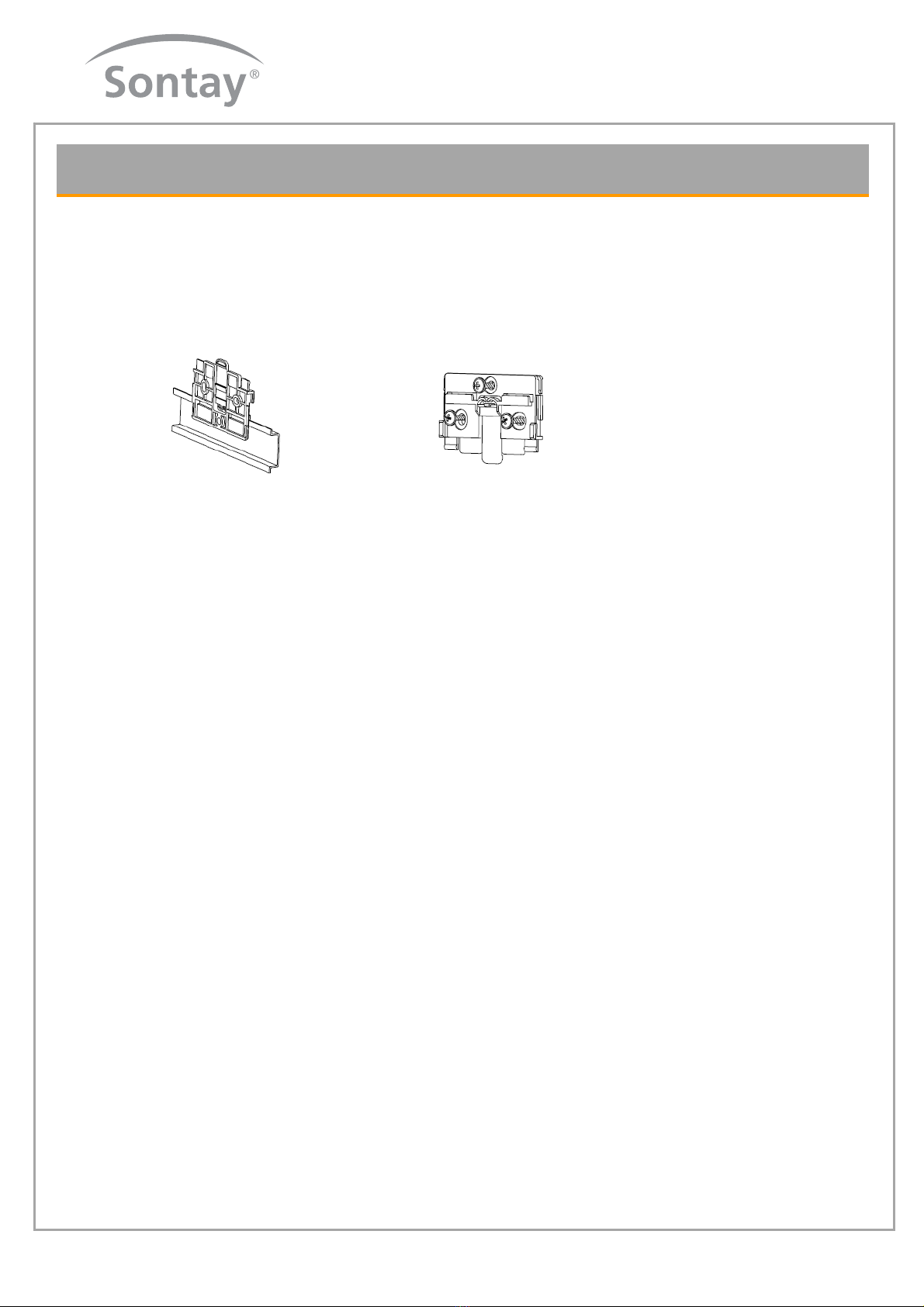
Installation (continued):
Installation heat calculator
Sontay recommends mounting the calculator on the wall. Do not mount the device at the pipe or attach it directly on the flow sensor.
The mounting adapter at the backside of the calculator can be used for DIN-rail mounting or “reverse” for wall mounting.
For wall mounting attach the adapter with at least two screws to the wall and clip the calculator on it.
For rail mounting lift the adapter a little bit, place the calculator on the rail and push the adapter back until it locks.
DIN-rail mounting Wall mounting
Connection sensors
The mounting of the temperature sensors should be done symmetrical with direct immersion. If immersion sleeves are used they have
to be checked for conformity to MID and have to be marked accordingly. The installation of immersion sleeves has to be done
according to DIN EN 1434-2.
The sensor cables are marked with colours (red = supply, blue = return). Do not buckle, extend or shorten the wire.
Do only use paired sensors with the same serial number on it.
Supply and return sensors must be inserted into the immersion sleeves completely.
Installation points in the flow sensor can be used for symmetrical installation of the temperature sensors.
Seal temperature sensor after installation to prevent unauthorized demounting (seals included).
Do not wrap or install wires along hot pipes.
Connection flow sensor
The total length of the wire between flow sensor and calculator should not exceed 2m. Mind the polarity at electronic flow sensors.
Operation test
Check the calculator for any error codes in the display after installation (see Page 5 for error codes). Most of the errors can be deleted
by pressing the button.
If the error appears permanently, it will be detected at the next measuring cycle and displayed again. Check whether the volume
information is updated and the displayed temperatures correspond to the present ones while the system is running (measuring cycle 2
minutes max.).
When attaching the top cover on the housing pulses on the inputs can possibly be generated. Check readings of the inputs and correct
if necessary.
Sealing
Seal the device with the included seals to prevent unauthorized opening.
Maintenance
Repairs or overhaul are only allowed by the manufacturer or companies authorized by the manufacturer.

Page 5 of 8
MW-U
Date of Issue: 12
/
03/2013
Issue Number: 5.3
Tel: +44 (0) 1732 861200 - E-mail: [email protected] - Web: www.sontay.com
© 2012 Sontay Limited. All rights reserved
Outputs:
Pulsed:
The pulse value of the outputs is permanently set and corresponds with the last position of the associated display value.
Example:
Output 1 = energy output
Energy display = XXXXX.XX MWh
Last position = 0.01 MWh = 10 kWh
Output pulse = 10 KWh
M-Bus:
The M-Bus interface complies with the norm EN 1434-3 and operates with 2400 baud fixed. It can be set to 300/6900 baud if
necessary.
Connections
Inputs:
Temperature sensors
Supply (hottest pipe) 1 & 2
Return (coolest pipe) 3 & 4
Flow sensor pulse 10 & 11 (GND)
If water meters with a potential free reed contact are connected to
the inputs the connection can be made in any direction.
Outputs:
Energy output pulse 52 & 53 (GND)
Volume output pulse 54 & 55 (GND)
Care must be taken when connection is made to a BMS.
M-Bus (M-Bus connections are given twice for incoming and outgoing of the M-Bus wires).
L1 24
L2 25
The symbols in the table below show the meter’s operational status. The status messages only appear in the main display (energy)! The
temporary display of the warning triangle can be caused by special operating states and does not always mean that the device is
malfunctioning. However, should the symbol be displayed over a longer period of time you should contact Sontay.
Symbol Status Event
Flow existent -
Attention Check for errors
Data transmission -
Emergency operation Exchange device
External power supply -
tp tp
3 ...30V
0V
400m/s < tp < 300m/s
Error Codes:
Error codes show faults detected by MW-MD. If more than one error
appears, the sum of the error codes is displayed: Error 1005 = error 1000
and error 5.
Code Error Event
1 Short-circuit return sensor Check sensors
2 Interruption return sensor “
3 Short circuit supply sensor “
4 Interruption supply sensor “
5 Hardware error Exchange device
6 Battery empty/wrong temp sensor Check
7 Temp. out of measuring range Correction of heating system
100 Emergency operation Exchange device
1000 Battery life time exceeded “
2000 Initial verification expired “
>8000 Internal hardware error “
Page 6 of 8
MW-U
Date of Issue: 12
/
03/2013
Issue Number: 5.3
Tel: +44 (0) 1732 861200 - E-mail: [email protected] - Web: www.sontay.com
© 2012 Sontay Limited. All rights reserved
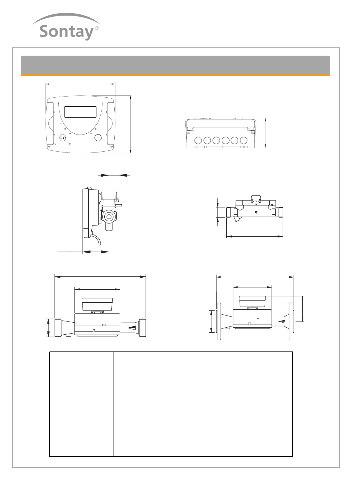
Dimensions:
126mm
106mm
54mm
22.6
59.5
L
GxB
L
150
GxB
L
H
DN
150
Nominal Flow qp m³/h 0,6 1 1,5 2,5 3,5 10 15 25 40 60
Nominal Diameter DN mm 15 15 15 20 25 40 50 65 80 100
lnch ½ ½ ½ ¾ 1 1 ½ - - - -
Inst. Length without conn. L mm 110 110 110 130 260 300 270 300 300 360
ThreadmeterGxB D1lnch¾¾¾11¼2FlangeFlangeFlangeFlange
Maximum Flow qi m³/h 1,2 2 3 5 7 20 30 50 80 120
Minimum Flow qs l/h 12 20 30 50 35 100 150 250 400 600
Operating Pressure, max. PN bar 16 16 16 16 16 16 25 25 25 16/25
Pressure loss at Qn bar 0,14 0,06 0,13 0,2 0,06 0,12 0,1 0,1 0,16 0,14
Weight kg 1 1 1 1,5 3 4 8 11 13 22

Page 7 of 8
MW-U
Date of Issue: 12
/
03/2013
Issue Number: 5.3
Tel: +44 (0) 1732 861200 - E-mail: [email protected] - Web: www.sontay.com
© 2012 Sontay Limited. All rights reserved
Display Loops:
Energy (main display)
Volume
Volume external counter 1
Volume external counter 2
Segment test
Supply temperature
Return temperature
Temperature difference
Flow
Maximum flow
Instantaneous power
Pulse value counter 1
Pulse value counter 2
Energy at SRD
Date SRD
SRD value external counter 1
SRD value external counter 2
Monthly values input 1
Monthly values input 2
Serial number
Customer number
Input 1 device number
Input 2 device number
Date month 1 energy consumption
Date month val. Input 1
Date month val. Input 1
Hold down the button (H)
until the device switches
to another level or
switches back from the
sub-menu.
Level 1 Level 2
Maximum power

Page 8 of 8
MW-U
Date of Issue: 12
/
03/2013
Issue Number: 5.3
Tel: +44 (0) 1732 861200 - E-mail: [email protected] - Web: www.sontay.com
© 2012 Sontay Limited. All rights reserved
Display Loops (continued)
Whilst every effort has been made to ensure the accuracy of this specification, Sontay cannot accept responsibility for damage, injury, loss or
expense from errors or omissions. In the interest of technical improvement, this specification may be altered without notice.
Level 1
1st monthly value heat energy
1st monthly value input 1
1st monthly value input 2
Sensor type & installation point
Pulse value
Basic configuration
Model number
Date battery end
Time
Datum
M-Bus address
Baud rate
Input display
Error status
Software version
Legend
Press the button briefly (S) to switch
through the display from top to
bottom. When you have reached the
last menu item the device
automatically jumps back to the menu
item at the top (loop).
Press the button for about 2 seconds
(L), wait for the door symbol to appear
(upper right corner of the display) and
then release the button. The menu is
then updated resp. switches to the
sub-menu.
Hold down the button (H) until the
device switches to another level or
switches back from the sub-menu.
Table of contents
Other Sontay Accessories manuals


