Sontay SonNet Trend Quick start guide

sip
SonNet-Trend
Interface Range
Technical Guide
Issue 1, Jun. 2014

© Sontay Limited
All rights reserved. No part of this document may be reproduced in any form or by any means - graphic,
electronic, or mechanical, including photocopying, recording, taping, or information storage and
retrieval systems - without the written permission of the publisher.
Products that are referred to in this document may be either trademarks and/or registered trademarks
of the respective owners. The publisher and the author make no claim to these trademarks.
While every precaution has been taken in the preparation of this document, the publisher and the
author assume no responsibility for errors or omissions, or for damages resulting from the use of
information contained in this document or from the use of the software that may accompany it. In no
event shall the publisher and the author be liable for any loss of profit or any other commercial damage
caused or alleged to have been caused directly or indirectly by the information contained in this
document.
Printed: Jun. 2014 in England

SIP SonNet-Trend - Interface Range
Error! Reference source not found. - Technical Guide
I
Contents
1INTRODUCTION......................................................................................................................................1
1.1THE UNIT 5
1.1.1 Front Panel Annunciation ............................................................................................................... 5
1.1.2 Button and Switches....................................................................................................................... 6
1.2SYSTEM OVERVIEW ..............................................................................................................................6
1.2.1 SonNet Network ............................................................................................................................. 8
1.2.2 Trend Network................................................................................................................................ 8
2HARDWARE GUIDE................................................................................................................................1
3INSTALLATION GUIDE...........................................................................................................................1
3.1INSTALLING THE UNIT ........................................................................................................................11
3.2HARDWARE CONTROL .......................................................................................................................13
3.2.1 Connections and Wiring................................................................................................................ 13
3.2.2 Power Supply ............................................................................................................................... 13
3.2.3 Communications........................................................................................................................... 14
3.2.4 Hardware Expansion .................................................................................................................... 16
4CONFIGURATION GUIDE.......................................................................................................................1
4.1THE CONFIGURATION PAGES ...........................................................................................................17
4.2CONNECT TO THIS PRODUCT............................................................................................................18
4.3CONFIGURE THE COMMS INTERFACE.............................................................................................20
4.3.1 Configure the Local IP Settings.................................................................................................... 20
4.3.2 Configure the Comms Settings..................................................................................................... 22
4.3.3 Configure the Map points.............................................................................................................. 24
4.3.4 Configure the Back up and Restore.............................................................................................. 28
4.4MANAGE THE LOGIN SECURITY........................................................................................................30

SIP SonNet-Trend - Interface Range
Error! Reference source not found. - Technical Guide
II
5VIQ CONFIGURATION GUIDE ...............................................................................................................1
5.1.1 Configure the VCNCs................................................................................................................... 33
5.1.2 Configure the Time and Date........................................................................................................ 34
5.1.3 Configure the UDP Group............................................................................................................. 35
5.1.4 Configure the GUID...................................................................................................................... 35
5.1.5 Save Plots to Flash....................................................................................................................... 36
5.1.6 Check the Network Status............................................................................................................ 38
5.1.7 Configure the Address Module..................................................................................................... 40
5.1.8 Configure a Sensors Module........................................................................................................ 41
5.1.9 Configure a Digital Inputs Module................................................................................................. 44
5.1.10 Configure a Knobs Module........................................................................................................... 44
5.1.11 Configure a Switches Module....................................................................................................... 47
5.1.12 Configure the Pin Level Authorisation .......................................................................................... 48
5.2USE THE VIQ CALCULATOR...............................................................................................................49
5.2.1 Create the vIQ Calculation............................................................................................................ 51
5.2.2 Configure the vIQ Calculation....................................................................................................... 53
5.2.3 Configure the ‘Frequency’ schedule ............................................................................................. 56
5.2.4 Replicate an Existing vIQ Calculation........................................................................................... 57
5.3TROUBLESHOOTING.............................................................................................................................1
6ORDER CODE.........................................................................................................................................1
6.1ACCESSORIES .....................................................................................................................................63

SIP SonNet-Trend - Interface Range
Contents
1INTRODUCTION......................................................................................................................................1
1.1THE UNIT 3
1.1.1 Front Panel Annunciation ............................................................................................................... 3
1.1.2 Button and Switches....................................................................................................................... 4
1.2SYSTEM OVERVIEW ..............................................................................................................................5
1.2.1 SonNet Network ............................................................................................................................. 6
1.2.2 Trend Network................................................................................................................................ 6
2HARDWARE GUIDE................................................................................................................................7
3INSTALLATION GUIDE...........................................................................................................................9
3 Issue 1, Jun. 2014
1 INTRODUCTION
This is a miniature computing platform that can be installed as part of a Trend BeMS (Building
energy Management System). It has been specifically designed to easily interface between the
Sontay SonNet Wireless Receiver, and a Trend BeMS (Building energy Management System). It
supports
SonNet proprietary protocol via P1
direct connection to Trend network allowing devices to appear as a Trend IQ3 controller via
the Ethernet port
standard or IP alarm conditions
Note We also provide an interface to a BACnet BeMS.
SIP SonNet-Trend - Interface Range
Contents
1INTRODUCTION......................................................................................................................................1
1.1THE UNIT 3
1.1.1 Front Panel Annunciation ............................................................................................................... 3
1.1.2 Button and Switches....................................................................................................................... 4
1.2SYSTEM OVERVIEW ..............................................................................................................................5
1.2.1 SonNet Network ............................................................................................................................. 6
1.2.2 Trend Network................................................................................................................................ 6
2HARDWARE GUIDE................................................................................................................................7
3INSTALLATION GUIDE...........................................................................................................................9
4 Issue 1, Jun. 2014
Remember Energy metering is compulsory for buildings of a floor area >500M2. The owner
must be able to account for 90% of the consumed energy from each system, i.e.
heat, gas, lighting, water and electricity.
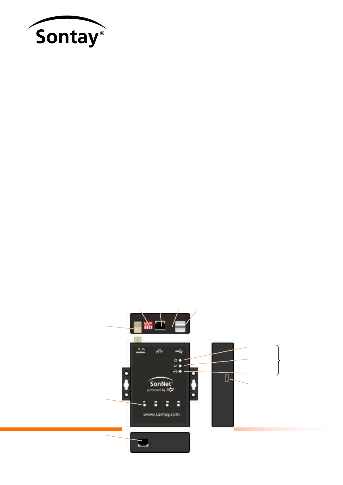
Ethernet
Port
USB2.0
Port (x2)
Reset
Button
DIP
Switch
24VDC
Power Supply
Serial Port LED’s
(P1 to P4)
Serial Port
1 port per LED
Status
LEDs
Power LED
Ready LED
LAN Activity
LED
Mini-USB Port

SIP SonNet-Trend - Interface Range
Contents
1INTRODUCTION......................................................................................................................................1
1.1THE UNIT 3
1.1.1 Front Panel Annunciation ............................................................................................................... 3
1.1.2 Button and Switches....................................................................................................................... 4
1.2SYSTEM OVERVIEW ..............................................................................................................................5
1.2.1 SonNet Network ............................................................................................................................. 6
1.2.2 Trend Network................................................................................................................................ 6
2HARDWARE GUIDE................................................................................................................................7
3INSTALLATION GUIDE...........................................................................................................................9
5 Issue 1, Jun. 2014
Remember Typically, individual systems (energy control, lighting, boiler and air conditioning
system, etc.) are individually measured for CO2 accountability. So, installing this
unit and combining the individual systems can help an effective BMS be more
energy efficient and comply with April 2006 Part L2 Building Regulations.
This product exposes information from SonNet ‘End devices’via its connection to a single
SonNet RF-RXS wireless receiver to the Trend BMS. Selected data, e.g. Amps, Voltage or
Temperature, from battery or permanently powered ‘End devices’ can be retrieved, logged (‘Map
points’ page), and presented (‘vIQ’ configuration pages’) allowing building managers prevent
outages, optimise the energy distribution and maintain building systems before any serious
problem occurs.
Each unit variant determines the maximum number of connected SonNet ‘End devices’,
including a default of 20 points per ‘End device’(see Error! Not a valid bookmark self-
reference.).
It is designed and manufactured to comply with CE Class A, FCC Class A, WEEE (Waste
Electrical and Electronic Equipment), RoHS (Restriction of Hazardous Substances) regulations
and the identification of a substance as Substance of Very High Concern (REACH).

SIP SonNet-Trend - Interface Range
Contents
1INTRODUCTION......................................................................................................................................1
1.1THE UNIT 3
1.1.1 Front Panel Annunciation ............................................................................................................... 3
1.1.2 Button and Switches....................................................................................................................... 4
1.2SYSTEM OVERVIEW ..............................................................................................................................5
1.2.1 SonNet Network ............................................................................................................................. 6
1.2.2 Trend Network................................................................................................................................ 6
2HARDWARE GUIDE................................................................................................................................7
3INSTALLATION GUIDE...........................................................................................................................9
6 Issue 1, Jun. 2014
It also complies with the requirements defined in the Council Directive on the Approximation of
the Laws of the Member States relating to Electromagnetic Compatibility (89/336/EEC). For the
evaluation regarding the electromagnetic compatibility, the following standards were applied
EN55022:1998/A1:2000+A2:2003 (class A)
EN61000-3-2:2000
EN61000-3-3:1995/A1:2001
EN55024:1998/A1:2001+A2:2003
IEC61000-4-2:1995+A1:1998+A2:2000
IEC61000-4-3:1995+A2:2002
IEC61 000-4-4:1995+A1:2000+A2:2001
IEC61000-4-5:1995+A1:2000
IEC61000-4-6:1996+A1:2000
IEC61 000-4-8:1993+A1:2000
IEC61000-4-11:1994+A1:2000

SIP SonNet-Trend - Interface Range
Contents
1INTRODUCTION......................................................................................................................................1
1.1THE UNIT 3
1.1.1 Front Panel Annunciation ............................................................................................................... 3
1.1.2 Button and Switches....................................................................................................................... 4
1.2SYSTEM OVERVIEW ..............................................................................................................................5
1.2.1 SonNet Network ............................................................................................................................. 6
1.2.2 Trend Network................................................................................................................................ 6
2HARDWARE GUIDE................................................................................................................................7
3INSTALLATION GUIDE...........................................................................................................................9
7 Issue 1, Jun. 2014
1.1 THE UNIT
The unit includes internal web based (html5) Configuration pages, designed to simplify the
engineering and configuration of the unit. The SIP SonNet-Trend displays each Sontay SonNet
wireless ‘End device’ communicating with the SonNet RF-RXS wireless receiver (connected at
P1) as a Trend IQ3 controller on the Trend BMS Supervisor.
It includes a set of pages that simplifies the
configuration of the IP settings for identifying the SIP on the IP network
configuration of communication requirements between the SIP and the SonNet RF-RXS
wireless receiver, and the SIP and the Trend BMS
configuration of the required ‘End device’ points and the mapping to the required vIQ OS
Note This product does not support alarms and plots.
1.1.1 Front Panel Annunciation
The LEDs on the unit are arranged in a group that indicate the general status of this product,
including Power, Ready and LAN communication activity and a group that shows the
communications activity with slave devices on the Sontay SonNet RF-RXS wireless receiver.
SIP SonNet-Trend - Interface Range
Contents
1INTRODUCTION......................................................................................................................................1
1.1THE UNIT 3
1.1.1 Front Panel Annunciation ............................................................................................................... 3
1.1.2 Button and Switches....................................................................................................................... 4
1.2SYSTEM OVERVIEW ..............................................................................................................................5
1.2.1 SonNet Network ............................................................................................................................. 6
1.2.2 Trend Network................................................................................................................................ 6
2HARDWARE GUIDE................................................................................................................................7
3INSTALLATION GUIDE...........................................................................................................................9
8 Issue 1, Jun. 2014
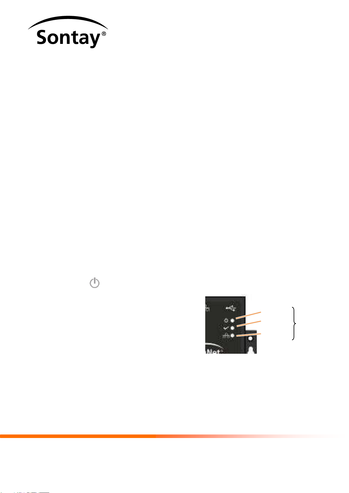
Power LED
This LED indicates the current status of
the power applied to the unit.
When continuously illuminated the 24VDC
power is supplied. If the LED is off, the power is
not supplied or has failed.
LAN
Activity
Statu
s
Power
LED
Ready

SIP SonNet-Trend - Interface Range
Contents
1INTRODUCTION......................................................................................................................................1
1.1THE UNIT 3
1.1.1 Front Panel Annunciation ............................................................................................................... 3
1.1.2 Button and Switches....................................................................................................................... 4
1.2SYSTEM OVERVIEW ..............................................................................................................................5
1.2.1 SonNet Network ............................................................................................................................. 6
1.2.2 Trend Network................................................................................................................................ 6
2HARDWARE GUIDE................................................................................................................................7
3INSTALLATION GUIDE...........................................................................................................................9
9 Issue 1, Jun. 2014
Ready LED
This LED indicates the current status of the boot up process.
When illuminated continuously the required files have been loaded to the RAM disk and the
unit has successfully booted up. If the LED is off, the unit is not ready or has failed to boot
up.
Ethernet (Activity) LED
This LED indicates the communication between this unit and the supervisory
computer or controller connected via the Ethernet.
When continuously illuminated the unit is currently connected to a device on the appropriate
Ethernet cable. If general Ethernet communications traffic is detected, the LED will
extinguish irregularly as communications traffic is detected. The LED is off (extinguished) if a
valid Ethernet connection is not detected.
Serial Ports LEDs
The P1 to P4 LEDs show the communication traffic between the unit and Sontay SonNet
RF-RXS wireless receiver connected via the corresponding Serial port, P1.

SIP SonNet-Trend - Interface Range
Contents
1INTRODUCTION......................................................................................................................................1
1.1THE UNIT 3
1.1.1 Front Panel Annunciation ............................................................................................................... 3
1.1.2 Button and Switches....................................................................................................................... 4
1.2SYSTEM OVERVIEW ..............................................................................................................................5
1.2.1 SonNet Network ............................................................................................................................. 6
1.2.2 Trend Network................................................................................................................................ 6
2HARDWARE GUIDE................................................................................................................................7
3INSTALLATION GUIDE...........................................................................................................................9
10 Issue 1, Jun. 2014
If outgoing communications traffic is detected, the LED will extinguish irregularly as
communications traffic is detected.
1.1.2 Button and Switches
The unit is fitted with a recessed button for controlling
the hardware and a Serial Interface switch for defining
the Sontay SonNet RF-RXS wireless receiver
communications standard.
Reset Button
This recessed button is used to reboot the unit. Operating this button will perform a reboot
that will restart the unit if the software fails.
Caution Only use the Reset button if the software reboot fails.
DIP Switches
The bank of 4 DIP switches is used to configure the Communications Standard used at P1
(see Hardware Control).
DIP
Reset

SIP SonNet-Trend - Interface Range
Contents
1INTRODUCTION......................................................................................................................................1
1.1THE UNIT 3
1.1.1 Front Panel Annunciation ............................................................................................................... 3
1.1.2 Button and Switches....................................................................................................................... 4
1.2SYSTEM OVERVIEW ..............................................................................................................................5
1.2.1 SonNet Network ............................................................................................................................. 6
1.2.2 Trend Network................................................................................................................................ 6
2HARDWARE GUIDE................................................................................................................................7
3INSTALLATION GUIDE...........................................................................................................................9
11 Issue 1, Jun. 2014
Note The unit is also fitted with connections that support power, communications, and
hardware expansion (see Hardware Control).
1.2 SYSTEM OVERVIEW
SIP SonNet-Trend - Interface Range
Contents
1INTRODUCTION......................................................................................................................................1
1.1THE UNIT 3
1.1.1 Front Panel Annunciation ............................................................................................................... 3
1.1.2 Button and Switches....................................................................................................................... 4
1.2SYSTEM OVERVIEW ..............................................................................................................................5
1.2.1 SonNet Network ............................................................................................................................. 6
1.2.2 Trend Network................................................................................................................................ 6
2HARDWARE GUIDE................................................................................................................................7
3INSTALLATION GUIDE...........................................................................................................................9
12 Issue 1, Jun. 2014
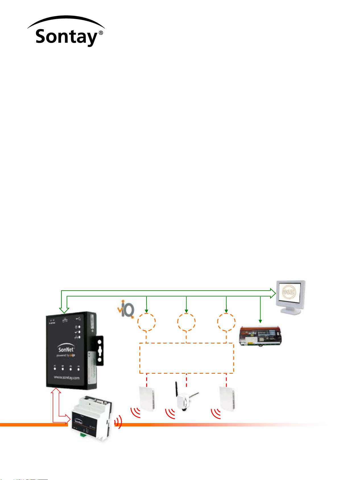
The system architecture is shown below.
Serial Network
IP Network
Each vIQ presents the configured SonNet
wireless ‘End device’ as Trend controller.
SonNet wireless ‘End device’ values are
transferred as Trend Sensor, Knob, Digital
Input and Switch Modules
OS26
OS11
OS50

SIP SonNet-Trend - Interface Range
Contents
1INTRODUCTION......................................................................................................................................1
1.1THE UNIT 3
1.1.1 Front Panel Annunciation ............................................................................................................... 3
1.1.2 Button and Switches....................................................................................................................... 4
1.2SYSTEM OVERVIEW ..............................................................................................................................5
1.2.1 SonNet Network ............................................................................................................................. 6
1.2.2 Trend Network................................................................................................................................ 6
2HARDWARE GUIDE................................................................................................................................7
3INSTALLATION GUIDE...........................................................................................................................9
13 Issue 1, Jun. 2014

SIP SonNet-Trend - Interface Range
Contents
1INTRODUCTION......................................................................................................................................1
1.1THE UNIT 3
1.1.1 Front Panel Annunciation ............................................................................................................... 3
1.1.2 Button and Switches....................................................................................................................... 4
1.2SYSTEM OVERVIEW ..............................................................................................................................5
1.2.1 SonNet Network ............................................................................................................................. 6
1.2.2 Trend Network................................................................................................................................ 6
2HARDWARE GUIDE................................................................................................................................7
3INSTALLATION GUIDE...........................................................................................................................9
14 Issue 1, Jun. 2014
1.2.1 SonNet Network
The Sontay® SonNet radio system is a proprietary protocol solely for use with SonNet wireless
‘End devices’ It. is comprised of a receiver, battery powered sensors and permanently powered
routers. Routers, though permanently powered, can also have sensing elements, accomplishing
both router and sensors functions.
Note This unit is connected directly to the SonNet RF-RXS wireless receiver.
The SonNet RF-RXS wireless receiver supports a maximum of 16 directly connected ‘child’
devices (max. 12 battery powered nodes, and max. 4 routers). Routers support a maximum of 16
directly connected ‘child’devices (max. 8 battery powered nodes, and max. 8 routers).
Caution A maximum depth of 8 layers of routers in a network and a maximum of 50 nodes
per network is permitted, but is dependent on the SIP SonNet-BACnet product.
Note Battery powered devices can only route their signals to the receiver directly or
through routers, and not through other battery powered devices.
Contact Sontay for a list of compatible ‘End devices’.

SIP SonNet-Trend - Interface Range
Contents
1INTRODUCTION......................................................................................................................................1
1.1THE UNIT 3
1.1.1 Front Panel Annunciation ............................................................................................................... 3
1.1.2 Button and Switches....................................................................................................................... 4
1.2SYSTEM OVERVIEW ..............................................................................................................................5
1.2.1 SonNet Network ............................................................................................................................. 6
1.2.2 Trend Network................................................................................................................................ 6
2HARDWARE GUIDE................................................................................................................................7
3INSTALLATION GUIDE...........................................................................................................................9
15 Issue 1, Jun. 2014
1.2.2 Trend Network
The vIQ (Virtual IQ) software enables this unit to present each SonNet wireless ‘End device’ as a
Trend IQ3 controller (OS (out-station)), directly onto the Trend network via a defined VCNC Node
and Port. The defined VCNC Node also represents a Node (OS) on the network.
Remember OSs (and VCNCs) are subject to the constraints imposed by the Trend network,
e.g. Node 2, Node 3 and Node 10 are reserved.
Each transferred SonNet wireless ‘End device’ value has a default configuration which relates to
a standard Trend module (sensor, digital Input, knob, and switch). The vIQ has the full
complement of functionality such as labels, alarms and plots.

SIP SonNet-Trend - Interface Range
Contents
1INTRODUCTION......................................................................................................................................1
1.1THE UNIT 3
1.1.1 Front Panel Annunciation ............................................................................................................... 3
1.1.2 Button and Switches....................................................................................................................... 4
1.2SYSTEM OVERVIEW ..............................................................................................................................5
1.2.1 SonNet Network ............................................................................................................................. 6
1.2.2 Trend Network................................................................................................................................ 6
2HARDWARE GUIDE................................................................................................................................7
16 Issue 1, Jun. 2014
2 HARDWARE GUIDE
This hardware provides an interface between devices communicating via an identified protocol,
i.e. SonNet, and Trend products communicating including 963, IQ4, IQ3 or IQ2 and EINC or
XTEND via Ethernet protocol. The unit should be installed in systems for monitoring and control
purposes.
General
Ethernet
Port
USB2.0
Port (x2)
Reset
Button
DIP
Switch
24VDC
Power Supply
Serial Port LEDs
(P1 to P4)
Serial Port
Status
LEDs
Power LED
Ready LED
LAN Activity
LED
Mini-USB Port
78mm
90mm
102mm
108mm
32mm
7mm
4mm
25mm
12.5mm

SIP SonNet-Trend - Interface Range
Contents
1INTRODUCTION......................................................................................................................................1
1.1THE UNIT 3
1.1.1 Front Panel Annunciation ............................................................................................................... 3
1.1.2 Button and Switches....................................................................................................................... 4
1.2SYSTEM OVERVIEW ..............................................................................................................................5
1.2.1 SonNet Network ............................................................................................................................. 6
1.2.2 Trend Network................................................................................................................................ 6
2HARDWARE GUIDE................................................................................................................................7
17 Issue 1, Jun. 2014
Weight 330g per unit including DIN Rail clips
410g shipped including DIN Rail clips
Power Input 24VDC ±15V regulated
Power Consumption 300mA@12VDC, 150mA@24VDC
Default User name Admin (case-sensitive)
Default Password password (case-sensitive)
Hardware Details
Button Reset
DIP Switch 1 bank of 4 switches
Indicators Power, System Ready, Ethernet LAN Activity, 4 x Serial
Communications Activity (one per port)
Ethernet 1 x 10/100Mbps port via RJ45 connector with 1.5KV
magnetic isolation
Serial 1 x TTY port via RJ45 connector, supporting connection to
Sontay SonNet RF-RXS wireless receiver
Note Only P1 is configured via the DIP Switch.
USB 2 x USB2.0 compliant host ports supporting low-speed
(1.5Mbps) and full-speed (12Mbps) data rate

SIP SonNet-Trend - Interface Range
Contents
1INTRODUCTION......................................................................................................................................1
1.1THE UNIT 3
1.1.1 Front Panel Annunciation ............................................................................................................... 3
1.1.2 Button and Switches....................................................................................................................... 4
1.2SYSTEM OVERVIEW ..............................................................................................................................5
1.2.1 SonNet Network ............................................................................................................................. 6
1.2.2 Trend Network................................................................................................................................ 6
2HARDWARE GUIDE................................................................................................................................7
18 Issue 1, Jun. 2014
SD Memory Card 1 x internal 2GB slot for storage expansion
Environmental
Storage Temperature -20 to 80C (-4 to 176F), 0 to 90% Relative Humidity
Operating Temperature 0 to 70C (32 to 158F), 0 to 90% Relative Humidity
Regulations CE Class A, FCC Class A, REACH (Regulation on
Registration, Evaluation, Authorisation and Restriction of
Chemicals - European Chemicals Agency), RoSH
(Restriction of the Use of Certain Hazardous Substances in
Electrical and Electronic Equipment - EU Directive
2002/95/EC)
RoHS BANNED SUBSTANCES
MAXIMUM
LIMIT (PPM)
Cadmium (Cd)
100
Lead (Pb)
1000
Mercury (Hg)
1000
Hexavalent Chromium (Cr6+)
1000
Poly Brominate Byphenyls (PBB)
100
Table of contents
Popular Recording Equipment manuals by other brands

TC-Helicon
TC-Helicon Play Electric manual

Sonance
Sonance Automatic Speaker Level Source Selector AS2 instruction manual

Omnitronic
Omnitronic KEY-288 user manual

Squarp Instruments
Squarp Instruments HAPAX manual

Delta
Delta UT-4 user manual

National Instruments
National Instruments NI PCIe-8233 Getting started

PIONEER DJ
PIONEER DJ DJS-1000 operating instructions

ICS ELECTRONICS
ICS ELECTRONICS 4809A instruction manual

Qu-Bit Electronix
Qu-Bit Electronix RT60 user manual

Tascam
Tascam Portastudio MF-P01 owner's manual

Elson
Elson CBi Installation & servicing instructions

Wheatstone
Wheatstone TV 1000 Technical manual


