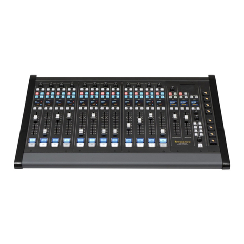
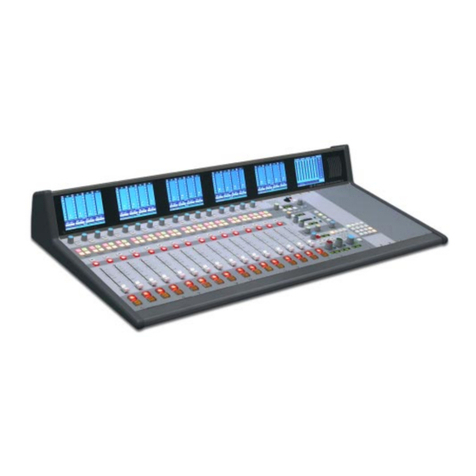
Wheatstone TV 1000 User manual

TV-1000Audio Console
TECHNICALMANUAL
600 Industrial Drive, New Bern, North Carolina, USA 28562

WHEATSTONE CORPORATION
600 Industrial Drive
New Bern, North Carolina 28562
tel 252-638-7000 / fax 252-637-1285
TV-1000 Live Television Audio Console Technical Manual - 2nd Edition (revised)TV-1000 Live Television Audio Console Technical Manual - 2nd Edition (revised)
TV-1000 Live Television Audio Console Technical Manual - 2nd Edition (revised)
©1998 Wheatstone Corporation
TV-1000 / Oct 98

Addenda
TV-1 / June 00
IMPORTANT:
Please note the following updates
to this technical manual:
ROUTER CONTROLLER RACKMOUNT POWER SUPPLY
SCHEMATIC & PARTS LIST (PCS-125):
Slow Blow Fuse F1 is now 1.25AMP.
SMARTSELECTCAGE(monoswitchercard)SCHEMATIC&PARTS
LIST (SS-MI-8S):
Regulator Q1 has been changed to a PQ05 SZ1 5V 1A.
Resistors R1-R9 are now 619 OHM 1% .25W.
!
Addenda - Page 1

INSERT POINT SHIPPING SHEET
ATTENTION!
Signal Path Insert Points
This TV-1000 audio console is equipped with insert
patch points on the following modules:
Submasters
AUX master signals
SUBMASTER signals
StereoMasters
STEREO MASTER output signals
Unless these points are jumpered (either internally via
PCB-mounted jumpers OR looped through at each
module’s DB-25 rear panel connector) audio signal
will not pass.
As shipped from the factory, PCB-mounted insert
jumpers have already been installed. If you intend to
use outboard signal loops at these points, you must
remove the factory installed jumpers.
See“SubmasterModuleInternalProgramming”
(Chapter 3) and “Master Module Internal Program–
ming”(Chapter 4) inthe TV-1000 Technical Manual for
details.
NOTE: While input modules also have insert points, these may simply be front panel
bypassed by an “insert” switch at the top of each module.

DUAL FAILSAFE POWER SUPPLIES
WHEATSTONE AUDIO CONSOLESMay 1998
ATTENTION!
DualRedundantPowerSupplies
If your Wheatstone audio console has been ordered
and shipped with a failsafe power supply system, it
usesTWOseparate rackmount power supplies. Though
either is capable of running the console on its own, in
failsafe operation both units run in tandem: if one fails,
the other takes over, assuring uninterrupted console
operation.
Dual failsafe supplies have their output trimmed to
entirely different settings than stand-alone single units,
and are MEANT to be run in tandem. If they are not, and
you attempt to “save” one supply by powering it down and
holding it in reserve until you run into an actual failure
condition, you could shorten the life expectancy of the
working unit.
!
In order for the failsafe system to perform as
designed,alwayshaveBOTH rackmount
supplies powered up and connected to the
console.

MAIN CONSOLE POWER
PSC-1000
#1
PSC-1000
#2
PWR IN 1A
PWR IN 1B
PWR IN 2A
PWR IN 2B
5 RU
5 RU
PSC-1000's connect to the
Power Interface Module
PWR-1000
SMART SELECT
RCC / BUTTON
POWER
PSC-125 #1 PWR IN 1
PWR IN 2
2 RU
PSC-125's connect to the
optional RCC-1000 or the
Smart Select Button power
connectors
PSC-125 #2
2 RU
SMART SELECT
CAGE POWER
PSC-340 #1
3 RU
PSC-340 #2
3 RU
CAGE #1
CAGE #2
5 RU
5 RU
*SPLITTERS
#1
#2
*NOTE: If installing redundant
cage power to a single cage,
the two splitters are not
required.
DEVICE RACKUNITS TOTAL POWER REQUIREMENTS
PSC-1000 #1
PSC-1000 #2 5 (8 3/4")
5 (8 3/4") 1500W TOTAL
PSC-125 #1
PSC-125 #2 2 (3 1/2")
2 (3 1/2") 200W TOTAL
PSC-340 #1
PSC-340 #2 3 (5 1/4")
3 (5 1/4") 400W TOTAL
SPLITTER #1
SPLITTER #2 1 (1 3/4")
1 (1 3/4") N / A
CAGE #1
CAGE #2 5 (8 3/4")
5 (8 3/4") N / A
NOTES: •Power totals assume redundant power supplies are installed.
•Complete system should be run from two 120 VAC/20 AMP circuits.
POWER SUPPLY AND SMART SELECT
INSTALLATION GUIDE
TV-1000 / Oct 00
SYSTEM TOTAL = 2100W

EXTRACTOR TOOLS
Your Wheatstone TV-1000 audio console is equipped with two
"module extractor tools" which are mounted underneath the
console armrest, to the far right (just in front of the operator’s
mainframe headphone jack).
Main module faceplates are held into the console mainframe by three
fasteners: a lower rear panel screw (below the module’s I/O connectors,
located at the rear of the console beneath the meterbridge assembly) and
two faceplate mounting screws (top and bottom) located on the control
surface of the console. The faceplate mounting screws, when removed,
leave specially threaded holes that accept the two extractor tools.
To remove a module faceplate from the mainframe:
Remove the rear panel screw, then the front top and bottom mounting
screws. Remove the extractor tools from underneath the armrest, and
screw each tool into a module faceplate mounting hole. Use only four or
five turns (do not over-insert; you may damage the threaded mainframe
hole underneath). Using the extractor tools as handles, pull the module
straight up out of the mainframe.
ModuleRemovalTools

CONTENTS
Contents – 1
TV1 / May 98
Table of Contents
Chapter 1 — Installation
Console Placement .................................................................... 1-2
Factory Leg Support System .................................................... 1-2
System Ground .......................................................................... 1-2
Power Supplies .......................................................................... 1-4
Failsafe Dual Redundant Supply............................................................................ 1-5
Energizing the Supplies.......................................................................................... 1-5
Audio and Control Wiring.......................................................... 1-6
The Insulation Displacement Connector System ................................................... 1-6
ConnectionProcedures .......................................................................................... 1-7
Insert Points............................................................................................................ 1-8
UnbalancedConnections ....................................................................................... 1-8
Quick Reference Module Pinouts........................................................................... 1-8
Chapter 2 — Stereo Mic/Line Inputs
General........................................................................................ 2-5
Main Module ............................................................................... 2-6
Input section ........................................................................................................... 2-6
AUX section ............................................................................................................ 2-6
BAL/MIX Control - Mode Switch ............................................................................. 2-6
Bus Assign .............................................................................................................. 2-7
Equalizationsection................................................................................................ 2-7
Peak LED................................................................................................................ 2-7
Cue and Solo .......................................................................................................... 2-7
Direct Out................................................................................................................ 2-7
Preselector Panel ....................................................................... 2-8
Input Fader Panel ....................................................................... 2-8
Fader....................................................................................................................... 2-8
Mute Groups ........................................................................................................... 2-8
Mix Minus................................................................................................................ 2-9
Ready LED.............................................................................................................. 2-9
Channel ON ............................................................................................................ 2-9
Bus Minus®Foldback.............................................................................................. 2-9
Metering .................................................................................... 2-10
Input Module External Control Ports...................................... 2-11
Remote On and Off............................................................................................... 2-11
Ready LED............................................................................................................ 2-11
On Tally................................................................................................................. 2-12
TV1 / Aug 99

CONTENTS
Contents – 2
TV1 / May 98
EFS On/Off ........................................................................................................... 2-12
Machine Start and Stop ........................................................................................ 2-12
Cough ................................................................................................................... 2-12
Talkback to Control Room .................................................................................... 2-12
Input Module Logic Programming.......................................... 2-13
Mute/Tally ............................................................................................................. 2-13
Cue Dropout.......................................................................................................... 2-13
Timer Restart ........................................................................................................ 2-14
Mix Minus.............................................................................................................. 2-14
Bus Minus®.............................................................................................................................................................................2-14
Sum LED VU ladder ............................................................................................. 2-14
AUX sends ............................................................................................................ 2-15
Mute Link .............................................................................................................. 2-15
Event Computer Start/Stop/Timer Enable ............................................................ 2-16
Mute Follow Connector ........................................................... 2-16
Input Module Audio Wiring ..................................................... 2-16
I/O Pinout Drawing................................................................................................ 2-17
Parts Lists (located in Chapter 10)
MLS-1000 module .............................................................................................. 10-15
main card (MLS-1000) ................................................................................. 10-17
switch card (MLSW-1000)............................................................................ 10-19
Fader panel......................................................................................................... 10-23
main card (FPI-1000) ................................................................................... 10-24
switch card (FPSW-1000; optional) ............................................................. 10-26
Printed Circuit Board Load Sheets
(TECHNICAL DRAWINGS booklet)
MLS-1000 main PCB ......................................................................................... TD-16
MLSW-1000 switchcard PCB ............................................................................ TD-22
FPI-1000 fader panel main PCB........................................................................ TD-49
Schematics
(TECHNICAL DRAWINGS booklet)
MLS-1000 main PCB ........................................................................................... TD-9
MLSW-1000 switchcard PCB ............................................................................ TD-17
FPI-1000 fader panel main PCB........................................................................ TD-46
Chapter 2 — Mono Mic/Line Inputs
General...................................................................................... 2-18
Main Module ............................................................................. 2-19
Input section ......................................................................................................... 2-19
AUX section .......................................................................................................... 2-19
PAN Control .......................................................................................................... 2-19
Bus Assign ............................................................................................................ 2-19
Equalizationsection.............................................................................................. 2-19
Peak LED.............................................................................................................. 2-19

CONTENTS
Contents – 3
TV1 / May 98
Cue and Solo ........................................................................................................ 2-20
Direct Out.............................................................................................................. 2-20
Preselector Panel ..................................................................... 2-20
Input Fader Panel ..................................................................... 2-21
Fader..................................................................................................................... 2-21
Mute Groups ......................................................................................................... 2-21
Mix Minus.............................................................................................................. 2-21
Ready LED............................................................................................................ 2-21
Channel ON .......................................................................................................... 2-22
Bus Minus®Foldback............................................................................................ 2-22
Metering .................................................................................... 2-22
Input Module External Control Ports...................................... 2-23
Remote On and Off............................................................................................... 2-23
Cough ................................................................................................................... 2-23
Talkback to Control Room .................................................................................... 2-23
On Tally................................................................................................................. 2-24
Machine Start and Stop ........................................................................................ 2-24
EFS On/Off ........................................................................................................... 2-24
Machine Remote ON and OFF............................................................................. 2-24
Ready LED............................................................................................................ 2-24
Input Module Logic Programming.......................................... 2-25
Mute/Tally ............................................................................................................. 2-25
Cue Dropout.......................................................................................................... 2-25
Timer Restart ........................................................................................................ 2-26
Mix Minus.............................................................................................................. 2-26
Bus Minus®.............................................................................................................................................................................2-26
LED VU ladder...................................................................................................... 2-26
AUX sends ............................................................................................................ 2-27
Mute Link .............................................................................................................. 2-27
Event Computer Start/Stop/Timer Enable ............................................................ 2-27
Mute Follow Connector ........................................................... 2-28
Input Module Audio Wiring ..................................................... 2-28
I/O Pinout Drawing................................................................................................ 2-29
Parts Lists (located in Chapter 10)
MI-1000 module.................................................................................................. 10-27
main card (MI-1000)..................................................................................... 10-29
switch card (SISW-1000) ............................................................................. 10-32
Fader panel......................................................................................................... 10-23
main card (FPI-1000) ................................................................................... 10-24
switch card (FPSW-1000; optional) ............................................................. 10-26
Printed Circuit Board Load Sheets
(TECHNICAL DRAWINGS booklet)
MI-1000 main PCB ............................................................................................ TD-30
CONTENTS
Contents – 4
TV1 / May 98
MI-1000 switchcard PCB (“SISW-1000”)........................................................... TD-35
FPI-1000 fader panel main PCB........................................................................ TD-46
Schematics
(TECHNICAL DRAWINGS booklet)
MI-1000 main PCB ............................................................................................ TD-23
MI-1000 switchcard PCB (“SISW-1000”)........................................................... TD-31
FPI-1000 fader panel main PCB........................................................................ TD-46
Chapter 2 — Stereo Line Inputs
General...................................................................................... 2-30
Main Module ............................................................................. 2-31
Input section ......................................................................................................... 2-31
AUX section .......................................................................................................... 2-31
BAL/MIX Control - Mode Switch ........................................................................... 2-31
Bus Assign ............................................................................................................ 2-32
Equalizationsection.............................................................................................. 2-32
Peak LED.............................................................................................................. 2-32
Cue and Solo ........................................................................................................ 2-32
Direct Out.............................................................................................................. 2-32
Preselector Panel ..................................................................... 2-33
Input Fader Panel ..................................................................... 2-33
Fader..................................................................................................................... 2-33
Mute Groups ......................................................................................................... 2-33
Mix Minus.............................................................................................................. 2-34
Ready LED............................................................................................................ 2-34
Channel ON .......................................................................................................... 2-34
Bus Minus®Foldback............................................................................................ 2-34
Metering .................................................................................... 2-35
Input Module Control Port....................................................... 2-36
Machine Start and Stop ........................................................................................ 2-36
Remote On and Off............................................................................................... 2-36
Ready LED............................................................................................................ 2-36
Input Module Logic Programming.......................................... 2-37
Mute/Tally ............................................................................................................. 2-37
Cue Dropout.......................................................................................................... 2-37
Timer Restart ........................................................................................................ 2-38
Mix Minus.............................................................................................................. 2-38
Bus Minus®.............................................................................................................................................................................2-38
Sum LED VU ladder ............................................................................................. 2-38
AUX sends ............................................................................................................ 2-39
Mute Link .............................................................................................................. 2-39
Event Computer Start/Stop/Timer Enable ............................................................ 2-40
Mute Follow Connector ........................................................... 2-40

CONTENTS
Contents – 5
TV1 / May 98
Input Module Audio Wiring ..................................................... 2-40
I/O Pinout Drawing................................................................................................ 2-41
Parts Lists (located in Chapter 10)
SI-1000 module .................................................................................................. 10-35
main card (SI-1000) ..................................................................................... 10-37
switch card (SISW-1000) ............................................................................. 10-39
Fader panel......................................................................................................... 10-23
main card (FPI-1000) ................................................................................... 10-24
switch card (FPSW-1000; optional) ............................................................. 10-26
Printed Circuit Board Load Sheets
(TECHNICAL DRAWINGS booklet)
SI-1000 main PCB ............................................................................................. TD-44
SISW-1000 switchcard PCB.............................................................................. TD-35
FPI-1000 fader panel main PCB........................................................................ TD-49
Schematics
(TECHNICAL DRAWINGS booklet)
SI-1000 main PCB ............................................................................................. TD-37
SISW-1000 switchcard PCB.............................................................................. TD-31
FPI-1000 fader panel main PCB........................................................................ TD-46
Chapter 3 — Stereo Submasters
General........................................................................................ 3-3
Main Module Controls................................................................ 3-3
Aux Master Section................................................................................................. 3-3
Mix Minus Master Section ...................................................................................... 3-3
Mix Minus Confidence Feed ................................................................................... 3-4
Vu Trims.................................................................................................................. 3-4
Aux Section............................................................................................................. 3-4
Balance Pot ............................................................................................................ 3-4
Master Assign ......................................................................................................... 3-4
Talkback.................................................................................................................. 3-4
LED VU Ladders..................................................................................................... 3-4
Sub Peak LED ........................................................................................................ 3-4
Solo and Cue .......................................................................................................... 3-5
Fader Panel Controls ................................................................. 3-5
Submaster Insert Point ........................................................................................... 3-5
Fader....................................................................................................................... 3-5
Mix Minus Assign (optional).................................................................................... 3-5
Channel ON ............................................................................................................ 3-5
Sum VU................................................................................................................... 3-5
Mute Groups ........................................................................................................... 3-6
Metering ...................................................................................... 3-6
Submasters............................................................................................................. 3-6
Mix-Minus and Auxiliary Sends .............................................................................. 3-6

CONTENTS
Contents – 6
TV1 / May 98
Submaster Module Internal Programming............................... 3-6
AUX Solo ................................................................................................................ 3-6
AUX Insert Bypass.................................................................................................. 3-6
Mix Minus Solo ....................................................................................................... 3-7
Submaster Insert Bypass ....................................................................................... 3-7
Mix Minus................................................................................................................ 3-7
Sum LED VU........................................................................................................... 3-7
AUX Sends ............................................................................................................. 3-7
Cue Dropout............................................................................................................ 3-8
Submaster Module Audio Wiring.............................................. 3-8
I/O Pinout Drawing.................................................................................................. 3-9
Parts Lists (located in Chapter 10)
SUB-1000 module .............................................................................................. 10-45
Main card (SG-1000) ................................................................................... 10-47
Switch card (SGSW-1000)........................................................................... 10-50
Confidence feed card (SGCF-1000) ............................................................ 10-53
Fader panel......................................................................................................... 10-54
main card (FPO-1000) ................................................................................. 10-55
switch card (FPSW-1000) ............................................................................ 10-57
Printed Circuit Board Load Sheets
(TECHNICAL DRAWINGS booklet)
SG-1000 main PCB ........................................................................................... TD-60
SGSW-1000 switchcard PCB ............................................................................ TD-65
SGCF-1000 confidence feed PCB..................................................................... TD-67
FPO-1000 fader panel main PCB...................................................................... TD-75
FPSW-1000 fader panel switchcard PCB ......................................................... TD-77
Schematics
(TECHNICAL DRAWINGS booklet)
SG-1000 main PCB ........................................................................................... TD-53
SGSW-1000 switchcard PCB ............................................................................ TD-61
SGCF-1000 confidence feed PCB..................................................................... TD-66
FPO-1000 fader panel main PCB...................................................................... TD-72
FPSW-1000 fader panel switchcard PCB ......................................................... TD-76
Chapter 4 — Stereo Masters
General........................................................................................ 4-3
Main Module Controls................................................................ 4-3
Vu Trims.................................................................................................................. 4-3
Aux Section............................................................................................................. 4-3
Balance Pot ............................................................................................................ 4-4
Master Assign ......................................................................................................... 4-4
Outputs ................................................................................................................... 4-4
Tone Interrupt ......................................................................................................... 4-4
Peak LED................................................................................................................ 4-4
Solo and Cue .......................................................................................................... 4-4

CONTENTS
Contents – 7
TV1 / May 98
Fader Panel Controls ................................................................. 4-5
Insert Point.............................................................................................................. 4-5
Fader....................................................................................................................... 4-5
Mix Minus Assign (optional).................................................................................... 4-5
Channel ON ............................................................................................................ 4-5
Sum VU................................................................................................................... 4-5
Mute Group Assign ................................................................................................. 4-5
Metering ...................................................................................... 4-6
Stereo Masters ....................................................................................................... 4-6
Master Module Internal Programming...................................... 4-6
Master Insert Bypass .............................................................................................. 4-6
Mix Minus................................................................................................................ 4-6
Sum LED VU........................................................................................................... 4-6
AUX Sends ............................................................................................................. 4-7
Cue Dropout............................................................................................................ 4-7
Master Module Input/Output Wiring ......................................... 4-8
I/O Pinout Drawing (Master 1) ................................................................................ 4-9
I/O Pinout Drawing (Masters 2-4)......................................................................... 4-10
Parts Lists (located in Chapter 10)
MSTR-1000 module............................................................................................ 10-58
Main card (SG-1000) ................................................................................... 10-60
Switch card (SGSW-1000)........................................................................... 10-63
Confidence feed card (SGCF-1000) ............................................................ 10-66
Fader panel......................................................................................................... 10-67
main card (FPI-1000) ................................................................................... 10-68
switch card (FPSW-1000) ............................................................................ 10-70
Printed Circuit Board Load Sheets
(TECHNICAL DRAWINGS booklet)
SG-1000 main PCB ........................................................................................... TD-60
SGSW-1000 switchcard PCB ............................................................................ TD-65
SGCF-1000 tone interrupt PCB......................................................................... TD-71
FPO-1000 fader panel main PCB...................................................................... TD-75
FPSW-1000 fader panel switchcard PCB ......................................................... TD-77
Schematics
(TECHNICAL DRAWINGS booklet)
SG-1000 main PCB ........................................................................................... TD-53
SGSW-1000 switchcard PCB ............................................................................ TD-61
SGCF-1000 master interrupt PCB..................................................................... TD-70
FPO-1000 fader panel main PCB...................................................................... TD-72
FPSW-1000 fader panel switchcard PCB ......................................................... TD-76

CONTENTS
Contents – 8
TV1 / May 98
Chapter 5 — Control Room Monitor Module
General........................................................................................ 5-2
Controls ...................................................................................... 5-2
VU Trims ................................................................................................................. 5-2
Solo/Cue/ExternalCue ........................................................................................... 5-2
Monitor Select......................................................................................................... 5-2
Headphone Section ................................................................................................ 5-3
CR Section.............................................................................................................. 5-3
Mode Switch ........................................................................................................... 5-3
Tally Ports ............................................................................................................... 5-3
Metering ...................................................................................... 5-3
Solo/External .......................................................................................................... 5-3
Solo/Cue Logic Programming................................................... 5-4
HDPN/CR Interrupt Select...................................................................................... 5-4
Cue Enable ............................................................................................................. 5-4
CR/HDPN Dim ....................................................................................................... 5-5
CR/HDPN Mute ..................................................................................................... 5-5
Cue Speaker Output mode..................................................................................... 5-5
Headphone Output Options ...................................................... 5-5
HDPN Amp Output Mode ....................................................................................... 5-5
HDPN Line Output Pre/Post Select........................................................................ 5-5
“On-Air” Tally Port ..................................................................... 5-6
Control Room Module Audio Wiring ........................................ 5-6
I/O Pinout Drawing.................................................................................................. 5-7
Parts Lists (located in Chapter 10)
CRM-1000 module.............................................................................................. 10-71
Main card (CR-1000) .......................................................................................... 10-73
Switch card (CRSW-1000) ................................................................................. 10-75
Solo feed card (FPI-1000) .................................................................................. 10-77
Printed Circuit Board Load Sheets
(TECHNICAL DRAWINGS Booklet)
CR-1000 main PCB ........................................................................................... TD-89
CRSW-1000 switchcard PCB ............................................................................ TD-94
FPI-1000 PCB (solo ACN feed to CRM module) .............................................. TD-96
Schematics
(TECHNICAL DRAWINGS Booklet)
CR-1000 main PCB ........................................................................................... TD-85
CRSW-1000 switchcard PCB ............................................................................ TD-90
FPI-1000 PCB (solo ACN feed to CRM module) .............................................. TD-95

CONTENTS
Contents – 9
TV1 / May 98
Chapter 6 — Studio Monitor Module
General........................................................................................ 6-2
Controls ...................................................................................... 6-2
Studio VU Trims...................................................................................................... 6-2
Talkback Dim Trims ................................................................................................ 6-2
Monitor Select......................................................................................................... 6-2
Headphone Section ................................................................................................ 6-3
Studio Section......................................................................................................... 6-3
Mode Switch ........................................................................................................... 6-3
Tally Ports ............................................................................................................... 6-3
Studio Module Logic Programming ......................................... 6-4
HDPN Talkback Interrupt........................................................................................ 6-4
STUDIO/HDPN Dim ............................................................................................... 6-4
STUDIO/HDPN Mute ............................................................................................. 6-4
HDPN Amp Output Mode ....................................................................................... 6-4
HDPN Line Output Pre/Post Select........................................................................ 6-4
Studio “On-Air” Tally Port......................................................... 6-5
Studio Module Audio Wiring ..................................................... 6-5
I/O Pinout Drawing.................................................................................................. 6-6
Parts Lists (located in Chapter 10)
STM-1000 module .............................................................................................. 10-78
Main card (CR-1000) .......................................................................................... 10-80
Switch card (CRSW-1000) ................................................................................. 10-82
Printed Circuit Board Load Sheets
(TECHNICAL DRAWINGS Booklet)
CR-1000 main PCB ........................................................................................... TD-89
CRSW-1000 switchcard PCB ..........................................................................TD-94A
Schematics
(TECHNICAL DRAWINGS Booklet)
CR-1000 main PCB ........................................................................................... TD-85
CRSW-1000 switchcard PCB ............................................................................ TD-90
Chapter 7 — VU/Oscillator Module
General........................................................................................ 7-2
Module Controls......................................................................... 7-2
External Oscillator Enable ...................................................................................... 7-2
VU Trims ................................................................................................................. 7-2
Talkback.................................................................................................................. 7-3
External Meter Select ............................................................................................. 7-3
Oscillator Section.................................................................................................... 7-3
Timer Control .......................................................................................................... 7-3
Solo/Cue Master Dropout ....................................................................................... 7-3

CONTENTS
Contents – 10
TV1 / May 98
VO Module Input/Output Wiring................................................ 7-4
I/O Pinout Drawing.................................................................................................. 7-5
Parts Lists (located in Chapter 10)
VO-1000 module................................................................................................. 10-84
Main card (MO-1000).......................................................................................... 10-86
Switch card (MOSW-1000)................................................................................. 10-89
Timer control card (TCS-60)............................................................................... 10-90
Printed Circuit Board Load Sheets
(TECHNICAL DRAWINGS Booklet)
MO-1000 main PCB......................................................................................... TD-102
MOSW-1000 switchcard PCB ......................................................................... TD-104
TM-6SB Timer PCB ......................................................................................... TD-168
Solo/Cue Dropout Panel.................................................................................. TD-106
Schematics
(TECHNICAL DRAWINGS Booklet)
MO-1000 main PCB........................................................................................... TD-98
MOSW-1000 switchcard PCB ......................................................................... TD-103
TM-6 Timer ...................................................................................................... TD-169
Solo/Cue Dropout Panel.................................................................................. TD-105
Chapter 8 — Options
RCC Event Computer................................................................. 8-3
Event Computer Wiring........................................................................................... 8-4
Parts Lists (located in Chapter 10)
System access panel (RCC-1000) ............................................................ 10-100
Switch controller card (DSC-1000) ............................................................ 10-102
Buffer card (RBUF-6A)............................................................................... 10-104
Display strip card (DISP-8) ........................................................................ 10-105
Power Supply (PS-RC rackmount unit) ..................................................... 10-106
Backup Battery Charger (BB-1000) ........................................................... 10-108
Printed Circuit Board Load Sheets
(TECHNICAL DRAWINGS booklet)
RC-600 main PCB .................................................................................... TD-139
Switch controller card (DSC-1000) ........................................................... TD-143
Buffer card (RBUF-6A).............................................................................. TD-137
Display strip card (DISP-8) ....................................................................... TD-141
Power Supply (PSC-125 rackmount unit)................................................. TD-164
Schematics (TECHNICAL DRAWINGS booklet)
RC-600 main PCB .................................................................................... TD-138
Switch controller card (DSC-1000) ........................................................... TD-142
Buffer card (RBUF-6A).............................................................................. TD-136
Display strip card (DISP-8) ....................................................................... TD-140
Power Supply (PSC-125 rackmount unit)................................................. TD-165
Backup Battery Charger (BB-1000) .......................................................... TD-163

CONTENTS
Contents – 11
TV1 / May 98
Smart Select®Cage.................................................................... 8-5
Smart Select Audio Wiring...................................................................................... 8-5
Audio Connector Pinouts (stereo line).................................................................... 8-7
Audio Connector Pinouts (mono mic/line).............................................................. 8-8
Parts Lists (located in Chapter 10)
Rackmount unit (includes SS-MB-1 PCB) ................................................... 10-94
Stereo line switcher card (SS-SI-8) ............................................................. 10-95
Mono mic/line switcher card (SS-MI-8)........................................................ 10-96
Controller card (SS-C-1A)............................................................................ 10-97
Power Supply (PS-300 rackmount unit) ...................................................... 10-98
Printed Circuit Board Load Sheets (TECHNICAL DRAWINGS booklet)
Stereo line switcher card (SS-SI-8) .......................................................... TD-158
Mono mic/line switcher card (SS-MI-8)..................................................... TD-155
Smart Cage motherboard (SS-MB-1) ....................................................... TD-160
Power Supply (PS-300 rackmount unit) ................................................... TD-166
Schematics (TECHNICAL DRAWINGS booklet)
Stereo line switcher card (SS-SI-8) .......................................................... TD-156
Mono mic/line switcher card (SS-MI-8)..................................................... TD-153
Smart Cage motherboard (SS-MB-1) ....................................................... TD-159
Power Supply (PS-300 rackmount unit) ................................................... TD-167
Confidence Module .................................................................... 8-9
Mix-Minus Interrupt ................................................................................................. 8-9
Stereo Master 1 Interrupt........................................................................................ 8-9
External Control .................................................................................................... 8-10
Internal Programming Options.............................................................................. 8-10
Confidence Module Wiring Diagram..................................................................... 8-11
Confidence Module Pinout Drawing ..................................................................... 8-12
Parts List (located in Chapter 10)..................................................................... 10-109
Schematic (TECHNICAL DRAWINGS booklet) ................................................ TD-78
Load Sheet Drawing (TECHNICAL DRAWINGS booklet) ................................ TD-81
Mute Master Panel.................................................................... 8-13
Mute Masters A thru D.......................................................................................... 8-13
Studio Mute Link ................................................................................................... 8-13
Parts List (located in Chapter 10)....................................................................... 10-93
Load Sheet Drawing (TECHNICAL DRAWINGS booklet) .............................. TD-110
Schematic (TECHNICAL DRAWINGS booklet) .............................................. TD-109
Tape Remote Panel .................................................................. 8-15
Timer ......................................................................................... 8-16
Parts List (located in Chapter 10)....................................................................... 10-90
Load Sheet Drawing (TECHNICAL DRAWINGS booklet) .............................. TD-168
Schematic (TECHNICAL DRAWINGS booklet) .............................................. TD-169
Chapter 9 — TV-1000 Power Systems
General........................................................................................ 9-2
PSC-1000 Console Power Supply............................................. 9-2
Alarm Circuit ........................................................................................................... 9-3
Thermal Protection ................................................................................................. 9-3
Rear Panel Wiring and Pinouts .............................................................................. 9-4
TV1 / Oct 98

CONTENTS
Contents – 12
TV1 / May 98
Parts Lists (located in Chapter 10)
Rackmount unit ............................................................................................ 10-10
Main PCB (PS-410) ..................................................................................... 10-12
Alarm PCB (PSA-1000) ............................................................................... 10-13
Printed Circuit Board Load Sheets (TECHNICAL DRAWINGS booklet)
PS-410 main PCB ..................................................................................... TD-128
PSA-1000 alarm PCB ............................................................................... TD-131
Schematics (TECHNICAL DRAWINGS booklet)
PS-410 main PCB ..................................................................................... TD-129
PSA-1000 alarm PCB ............................................................................... TD-130
Power Interface Module............................................................. 9-5
Rear Panel Pinouts................................................................................................. 9-5
Parts List – PWI-1000 Module (located in Chapter 10)..................................... 10-92
PWI-1000 PCB Load Sheet (TECHNICAL DRAWINGS booklet) ................... TD-108
PWI-1000 PCB Schematic (TECHNICAL DRAWINGS booklet)..................... TD-107
PS-RC Event Computer Power Supply .................................... 9-6
Wiring and Pinout Details ....................................................................................... 9-6
Parts List (located in Chapter 10)..................................................................... 10-106
Load Sheet Drawing (TECHNICAL DRAWINGS booklet) .............................. TD-164
Schematic (TECHNICAL DRAWINGS booklet) .............................................. TD-165
PS-300 Smart Select Cage Power Supply................................ 9-7
Wiring and Pinout Details ....................................................................................... 9-7
Parts List (located in Chapter 10)....................................................................... 10-98
Component Pictorials (TECHNICAL DRAWINGS booklet)............................. TD-166
Schematic (TECHNICAL DRAWINGS booklet) .............................................. TD-167
Chapter 10 — Parts Lists
Console Mainframe
Mainframe (typical, 71-Position) .................................................................. 10-3
Main module motherboards (MBM-1000).................................................... 10-5
Fader panel motherboards (MBF-1000) ...................................................... 10-6
Preselector panel motherboards (MBS-1000) ............................................. 10-7
Meter LED lamp card (LED-3) ..................................................................... 10-8
Extender module service card (EXT-1000) ................................................. 10-9
Console Power Supply
Rackmount unit (PSC-1000)...................................................................... 10-10
Main card (PS-410).................................................................................... 10-12
Alarm card (PSA-1000).............................................................................. 10-14
Relay card (PSR-1000)................................................................................ 14-a
Stereo Mic/Line Input Module
MLS-1000 module...................................................................................... 10-15
main card (MLS-1000) ........................................................................ 10-17
switch card (MLSW-1000)................................................................... 10-19
Fader panel ................................................................................................ 10-23
main card (FPI-1000) .......................................................................... 10-24
switch card (FPSW-1000; optional) .................................................... 10-26
TV1 / Apr 99

CONTENTS
Contents – 13
TV1 / May 98
Mono Mic/Line Input Module
MI-1000 module ......................................................................................... 10-27
main card (MI-1000)............................................................................ 10-29
switch card (SISW-1000) .................................................................... 10-32
Stereo Line Input Module
SI-1000 module.......................................................................................... 10-35
main card (SI-1000) ............................................................................ 10-37
switch card (SISW-1000) .................................................................... 10-39
Input Preselector
Overbridge panel (SB-1000)...................................................................... 10-42
Panel card (SB-1000) ................................................................................ 10-43
Controller Card (SBC-1000) ...................................................................... 10-44
Stereo Submaster Module
SUB-1000 module...................................................................................... 10-45
Main card (SG-1000) ................................................................................. 10-47
Switch card (SGSW-1000)......................................................................... 10-50
Confidence feed card (SGCF-1000).......................................................... 10-53
Fader panel ................................................................................................ 10-54
main card (FPI-1000) .......................................................................... 10-55
switch card (FPSW-1000) ................................................................... 10-57
Stereo Master Module
MSTR-1000 module ................................................................................... 10-58
Main card (SG-1000) ................................................................................. 10-60
Switch card (SGSW-1000)......................................................................... 10-63
Confidence feed card (SGCF-1000) .......................................................... 10-66
Fader panel ................................................................................................ 10-67
main card (FPI-1000) .......................................................................... 10-68
switch card (FPSW-1000) ................................................................... 10-70
Control Room Monitor Module
CRM-1000 module ..................................................................................... 10-71
Main card (CR-1000) ................................................................................. 10-73
Switch card (CRSW-1000)......................................................................... 10-75
Solo feed card (FPI-1000) ......................................................................... 10-77
Studio Monitor Module
STM-1000 module ..................................................................................... 10-78
Main card (CR-1000) ................................................................................. 10-80
Switch card (CRSW-1000)......................................................................... 10-82
VU/OscillatorModule
VO-1000 module ........................................................................................ 10-84
Main card (MO-1000)................................................................................. 10-86
Switch card (MOSW-1000) ........................................................................ 10-89
Timer control card (TCS-60) ...................................................................... 10-90
Solo/Cue Dropout Master
Switch panel............................................................................................... 10-91
TV1 / Apr 99
Table of contents
Other Wheatstone Recording Equipment manuals

Wheatstone
Wheatstone D-5000 User manual

Wheatstone
Wheatstone TV-80 User manual

Wheatstone
Wheatstone E-5 User manual

Wheatstone
Wheatstone D-8000 User manual

Wheatstone
Wheatstone ARCUS User manual

Wheatstone
Wheatstone A-6000 User manual

Wheatstone
Wheatstone GSX User manual

Wheatstone
Wheatstone E-Series Guide

Wheatstone
Wheatstone ARCUS User manual

Wheatstone
Wheatstone M-2 User manual
Popular Recording Equipment manuals by other brands

Korg
Korg DRV-1000 Service manual

SMC Networks
SMC Networks EX120-SDN1-X2 Operation manual

Daktronics
Daktronics SPORTS WIRE 4000 INTERFACE Installation & operation manual

Alpine
Alpine KCX-C2600B owner's manual

Musicom Lab
Musicom Lab EFX MK-V owner's manual

Pepperl+Fuchs
Pepperl+Fuchs IDENTControl IC-KP2-2HB18-2V1 manual