Sony Ericsson MZ-E35 User manual

MICROFILM
SERVICE MANUAL
PORTABLE MINIDISC PLAYER
US Model
AEP Model
UK Model
E Model
Model Name Using Similar Mechanism NEW
MD Mechanism Type MT-MZE35-140
Optical Pick-up Type ODX-1B
SPECIFICATIONS
MZ-E35
US and foreign patents licensed from Dolby
Laboratories Licensing Corporation.

– 2 –
TABLE OF CONTENTS
1. GENERAL ................................................................... 3
2. DISASSEMBLY ......................................................... 5
3. TEST MODE.............................................................. 8
4. ELECTRICAL ADJUSTMENTS......................... 11
5. DIAGRAMS
5-1. Block Diagram ................................................................ 13
5-2. Printed Wiring Board
(US, Hong Kong Model)................................................. 15
5-3. Printed Wiring Board
(AEP, UK, E, French Model).......................................... 19
5-4. Schematic Diagram ......................................................... 21
5-5. IC Pin Function Description ........................................... 30
6. EXPLODED VIEWS................................................ 33
7. ELECTRICAL PARTS LIST ............................... 35
SERVICING NOTES
Flexible Circuit Board Repairing
• Keep the temperature of the soldering iron around 270 ˚C dur-
ing repairing.
• Do not touch the soldering iron on the same conductor of the
circuit board (within 3 times).
• Be careful not to apply force on the conductor when soldering
or unsoldering.
Notes on chip component replacement
• Never reuse a disconnected chip component.
• Notice that the minus side of a tantalum capacitor may be dam-
aged by heat.
SAFETY-RELATED COMPONENT WARNING!!
COMPONENTS IDENTIFIED BY MARK !OR DOTTED
LINE WITH MARK !ON THE SCHEMATIC DIAGRAMS
AND IN THE PARTS LIST ARE CRITICAL TO SAFE
OPERATION. REPLACE THESE COMPONENTS WITH
SONY PARTS WHOSE PART NUMBERS APPEAR AS
SHOWN IN THIS MANUAL OR IN SUPPLEMENTS PUB-
LISHED BY SONY.
CAUTION
Use of controls or adjustments or performance of procedures
other than those specified herein may result in hazardous ra-
diation exposure.
This MiniDisc player is classified as a CLASS 1
LASER product.
The CLASS 1 LASER PRODUCT label is located
on the bottom exterior.

– 3 –
SECTION 1
GENERAL This section is extracted from
instruction manual.

– 4 –

– 8 –
SECTION 3
TEST MODE
300 V3.000
300
Remote controller LCD
Main unit LCD
ROM version
display (Ver3.00
or Ver3.20)
General
• In the TEST mode, this set provides the Auto mode in which
both CD and MO are adjusted automatically. In theAuto mode,
whether a disc is CD or MO is discriminated, then each
adjsutment is automatically executed sequentially. If a fault is
found, it is displayed.Also, in the Servo mode, each item can be
adjusted automatically.
EnteringTEST Mode
Bridge theTAP801 (TEST) on MAIN board (connect IC801 #™ to
GND), and turn the power on.
Then, press (key and the TEST mode is activated.
ReleasingTEST Mode
Turn the power off, and remove the bridge from TAP801 (TEST)
on MAIN board.
Operation inTEST Mode
In the TEST mode, the LCD display is as shown below:
• ROM version display → All ON → All OFF are repeated.
• To hold the display for confirmation, press the PLAY MODE
key.
Display in TEST Mode
+key
–key
+,
–
key
+,
–
key
+,
–
key
p
key
p
key
p
key
(
key
(
key
p
key
AUTO Mode
(Auto?)
SERVO Mode
0 0 0
AUDIO Mode
1 0 0
POWER Mode
3 0 0
MANUAL
Mode
(Manu?)
( ) for Remote controller LCD display
(Start?)
+,–key +,–key
p
key
p
key
p
key
p
key
p
key
p
key
123
(To page 9 )
SERVO Mode
0 0 0
OFFSET Adj.
0 1 0
Each time
(
key is press-
ed,
011-013
modes
are switched. (For each
mode, see relevant table)
Each time
(
key is press-
ed,
021-024
modes
are switched. (For each
mode, see relevant table)
Each time
(
key is press-
ed,
031-039
modes
are switched. (For each
mode, see relevant table)
LASER
POWER Adj.
0 2 0
MO Adj.
0 3 0
(
key
(
key
(
key
(
key
(
key
(
key
(
key
Configuration ofTEST Mode
The TEST mode configuration of this set is as follows:
SERVO Mode
• Enter the TEST mode, press VOL −key and (key to select
the SERVO mode.
• When the second digit of mode number is not 0 and the first
digit is 0 (010, 020, 030, etc.), the optical pickup moves to out-
side track or inside track with +key or =key respec-
tively.
• To select other modes, refer to the TEST mode configuration.
1. Configuration of SERVO Mode

– 9 –
+,–key+,–key+,–key+,–key
+,–key
p
key
p
key
p
key
p
key
p
key
p
key
p
key
p
key
p
key
p
key
123
(To page 8 )
(
key
(
key
(
key
(
key
(
key
(
key
(
key
(
key
(
key
(
key
LOW REF CD Adj.
0 4 0
CD Adj.
0 5 0
SLED Move
0 6 0
AUTO Adj.
0 7 0
NV
0 9 0
Each time
(
key is
pressed,
041-048
modes are switched.
(For each mode, see
relevant table)
Each time
(
key is
pressed,
051-058
modes are switched.
(For each mode, see
relevant table)
Each time
(
key is
pressed,
061
and
062
modes are switched.
(For each mode, see
relevant table)
Each time
(
key is
pressed,
071-074
modes are switched.
(For each mode, see
relevant table)
Each time
(
key is
pressed,
091-093
modes are switched.
(For each mode, see
relevant table)
Return to OFFSET Adj.
(
010
)
2. Description of Each Mode
010 Offset Adjustment
Mode Description
011 Focus error offset
012 Tracking error offset
013 All servo ON
020 Laser Power Adjustment
Mode Description
021 MO power A
022 MO power E
023 CDL power
024 CD power
030 MO Adjustment
Mode Description
031 MO EF balance (MO traverse)
032 MO EF gain
033 MO ABCD gain
034 MO focus gain
035 MO tracking gain
036 MO RF gain
037 MO ADIP gain
038 MO focus bias E
039 MO focus bias A
040 Low Reflection CD Adjustment
Mode Description
041 Low reflection CD EF balance
(CD traverse)
042 Low reflection CD EF gain
043 Low reflection CDABCD gain
044 Low reflection CD focus gain
045 Low reflection CD tracking gain
046 Low reflection CD RF offset
047 Low reflection CD RF gain
048 Low reflection CD focus bias
050 CD Adjustment
Mode Description
051 CD EF balance
052 CD EF gain
053 CD ABCD gain
(CD RF level check)
054 CD focus gain
055 CD tracking gain
056 CD RF offset
057 CD RF gain
058 CD focus bias

– 10 –
060 Sled Movement
Mode Description
061 Sled IN
062 Sled OUT 5
070 Auto Adjustment
Mode Description
071 Focus search
072 Access 32
073 ADER check
074 Tracking gain correction
090 NV
Mode Description
091 NV clear
092 Power OFF
093 Model discrimination code
AUDIO Mode
• Enter the TEST mode, and press VOL −key, (key, and VOL
+ key in this order to select the AUDIO mode.
• To select other modes, refer to the TEST mode configuration.
1. Configuration of AUDIO Mode
• The mode No.111 is for S/N and cross talk, and 115 for distor-
tion factor and frequency characteristic.
• When VOL + / −key is pressed in any mode, the headphone
volume changes every step.
Also,When +or =key is pressed, the headphone volume
becomes maximum or minimum.
• Once the volume level was changed, fundamentally it contin-
ues, but it returns to default value when the mode is changed
from 114 to 115, or 118 to 119.
p
key
p
key
p
key
p
key
p
key
p
key
p
key
p
key
p
key
p
key
(
key
(
key
(
key
(
key
(
key
(
key
(
key
(
key
(
key
(
key
(
key
1kHz 0dB L/R
1 1 1
Headphone
output
–– 12dB
––
∞
–– 12dB
–– 12dB
–– 20dB
–– 20dB
–– 20dB
–– 20dB
–– 40dB
Infinity Zero
1 1 2
1kHz 0dB L
1 1 3
1kHz 0dB R
1 1 4
1kHz 0dB L/R
1 1 5
20Hz 0dB L/R
1 1 6
20kHz 0dB L/R
1 1 7
100kHz De-Emphasis
1 1 8
100kHz 0dB L/R
1 1 9
AUDIO Mode
1 0 0
PLAY TEST
1 1 0

– 11 – – 12 –
SECTION 4
ELECTRICAL ADJUSTMENTS
p
key
(
key
p
key
(
key
(
key
POWER Mode
3 0 0
UNREG Check
3 1 0
POWER OFF
3 1 1
215 Auto?
Precautions on Adjustment
• In this set, the CD and MO adjsutment can be executed auto-
matically by selecting the TEST mode.
• Execute adjustment in the AUTO mode, then if NG occurred,
readjust faulty item in the SERVO mode.
Adjustment in AUTO Mode
1. Enter the TEST mode, and pressVOL + key to select theAUTO
mode.
2. Insert the CD Test disc (TDYS-1) or commercially available
SONY MO disc (already recorded).
3. Press (key twice, and the CD or MO is discriminated, then
respective items are automatically adjusted in the order as listed
in tables below.
• CD AUTO Adjustment
No. Mode Description
1061 Sled IN
2071 Focus search
3062 Sled OUT 5
4051 CD EF balance
5052 CD EF gain
6051 CD EF balance
7053 CD ABCD gain
8054 CD focus gain
9055 CD tracking gain
10 056 CD RF offset
11 057 CD RF gain
12 056 CD RF offset
13 058 CD focus bias
14 073 ADER check
15 074 Biaxial gain correction
POWER Mode
•Enter the TEST mode, and pressVOL −key, (key, and VOL
−key in this order to select the POWER mode.
•To select other modes, refer to the TEST mode configuration.
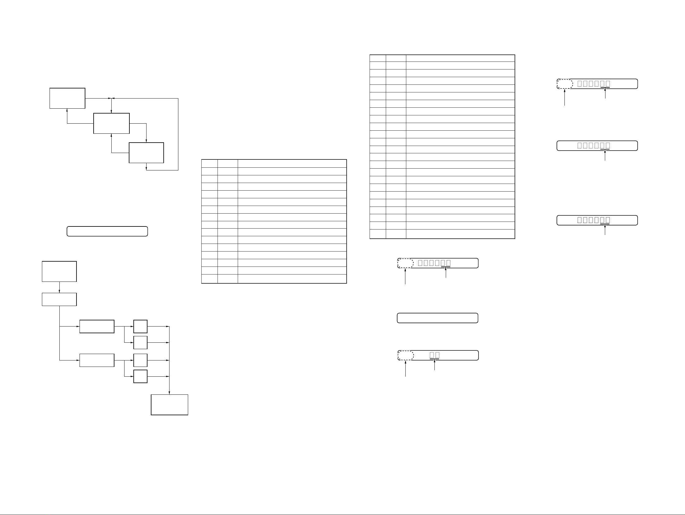
1. Configuration of POWER Mode
AUTO Mode
•Enter the TEST mode, and pressVOL + key to select theAUTO
mode.
•To select other modes, refer to the TEST mode configuration.
•In the AUTO mode, the Remote controller LCD display is as
shown below:
1.Configuration of AUTO Mode
p
key
p
key
p
key
p
key
(
key
(
key
(CD, MO discrimination)
CD Auto Adj.
MO Auto Adj.
Start?
OK
NG
OK
NG
MANUAL Mode
Manu?
AUTO Mode
Auto?
• MO AUTO Adjustment
No. Mode Description
1061 Sled IN
2071 Focus search
3062 Sled OUT
4031 MO EF balance
5032 MO EF gain
6031 MO EF balance
7033 MO ABCD gain
8034 MO focus gain
9035 MO tracking gain
10 036 MO RF gain
11 037 MO ADIP gain
12 039 MO focus bias A
13 073 ADER check
14 061 Sled IN
15 071 Focus search
16 041 Low reflection CD EF balance
17 042 Low reflection CD EF gain
18 041 Low reflection CD EF balance
19 043 Low reflection CD ABCD gain
20 044 Low reflection CD focus gain
21 045 Low reflection CD tracking gain
22 046 Low reflection CD RF offset
23 047 Low reflection CD RF gain
* Remote controller display during automatic adjustment.
4. If automatic adjustment result is OK, the display is as follows:
5. If automatic adjustment result is NG, the display is as follows:
* In case of NG, select the SERVO mode, and readjust NG item
automatically.
Adjustment in SERVO Mode
1. Select each adjusting mode following the configuration of
SERVO mode, and the lower 2 digits of mode number and the
adjusted value written to the EEPROM are displayed on the
LCD.
2. Press Pkey, and the display changes as shown below and
automatic adjustment is executed.
Note: Though the adjusted value can be changed to any value with VOL
+ or −key, avoid frequent change.
3. Whem automatic adjustment is finished, the adjusted value
changes from blinking to lighting.
057
Mode No. being adjusted
Adjusted value (blinking)
074 End-OK
051
NG mode No. Error code
NG
052
Mode No. Adjusted value (lighting)
052
Adjusted value (blinking)
052
Adjusted value (lighting)

– 21 –
Approx. 280 mVp-p
1IC501 6,7(V1, VJ) (Play Mode)
500 mV/DIV, 500 ns/DIV
Approx. 43 mVp-p
2IC501 0(IA) (Play Mode)
20 mV/DIV, 1 µs/DIV
3IC501 1,4(IE, IF) (Play Mode)
10 mV/DIV, 500 ns/DIV
Approx. 23 mVp-p
4IC501 #¶ (RF-OUT) (Play Mode)
200 mV/DIV, 500 ns/DIV
Approx. 760 mVp-p
5IC601 #ª (LRCK) (Play Mode)
1 mV/DIV, 10 µs/DIV
2.8 Vp-p
23
µ
s
6IC601 $¡ (BCK) (Play Mode)
1 V/DIV, 200 ns/DIV
2.8 Vp-p
355 ns
7IC301 5(XT1) (Play Mode)
500 mV/DIV, 20 ns/DIV
1.4 Vp-p
16.9344 MHz
• Waveforms

– 22 –
IC301 AK4334-VF-E2
IC302 BA3577FS-E2
• IC Block Diagrams

– 23 –
IC551 MPC17A55FTA

– 24 –
IC601 µPD63730AGC-9EU
IC901 MPC1830VMEL

– 25 –
5-5. IC PIN FUNCTION DESCRIPTION
•MAIN BOARD IC501 SN761050A (RF AMPLIFIER)
Pin No. Pin Name I/O Function
1 to 4 IE, ID, IC, IF I Signal input from the optical pick-up detector
5 AGND — Ground terminal (analog system)
6VII
I-V converted RF signal I input from the optical pick-up block detector
7VJI
I-V converted RF signal J input from the optical pick-up block detector
8 AVCC — Power supply terminal (+2.5V) (analog system)
9, 10 IB, IA I Signal input from the optical pick-up detector
11 PD-IN + I Light amount monitor input terminal (non-invert input)
12 PD-IN – I Light amount monitor input terminal (invert input)
13 PD-OUT O Light amount monitor output terminal
14 LD-DRV O Laser amplifier output terminal to the automatic power control circuit
15 LD-SNS I Laser drive current detector input terminal
16 LD-VDD I Laser power supply voltage detector input terminal
17 DVA1 I Serial device code A1 (fixed at “L” in this set)
18 VTEMP O Temperature sensor detection signal output to the system controller (IC801)
19 REXT1 — Connected to external resistor for the temperature sensor control
20 DVDD — Power supply terminal (+3V) (digital system)
21 SBUS I Serial data input from the system controller (IC801)
22 SCK I Serial data transfer clock signal input from the system controller (IC801)
23 DGND — Ground terminal (digital system)
24 RESET I System reset signal input from the MPC1830VMEL (IC901) “L”: reset
For several hundreds msec. after the power supply rises, “L” is input, then it changes to “H”
25 OFTRK O Oftrack detection signal output to the D.S.P. (IC601)
26 DFCT O Defect detection signal output to the D.S.P. (IC601)
27 EXT-IN I External timing count signal input terminal Not used (open)
28 T-COUNT O Timing count signal output to the D.S.P. (IC601)
29 ADIP O ADIP duplex signal (22.05 kHz ±1 kHz) output to the D.S.P. (IC601)
30 BPFC1 — Connected to the external capacitor for cutting the low band of the ADIP amplifier
31 BPFC0 — Connected to the external capacitor for cutting the low band of the ADIP amplifier
32 REXT2 — Connected to external resistor for the ADIP amplifier control
33 TE O Tracking error signal output to the D.S.P. (IC601)
34 OFTIN I Oftrack detection signal input terminal
35 ABCD O Light amount signal (ABCD) output to the D.S.P. (IC601)
36 FE O Focus error signal output to the D.S.P. (IC601)
37 RF-OUT O Playback EFM RF signal output to the D.S.P. (IC601)
38 MIRR-VTH I Threshold setting terminal for the mirror comparator
39 PS — Phase shifter for the RF amplifier
40 AGND — Ground terminal (analog system)
41 EQ-2 — Center frequency setting terminal for the internal circuit (RF EQ)
42 EQ-1 — Center frequency setting terminal for the internal circuit (RF EQ)
43 AVCC — Power supply terminal (+2.5V) (analog system)
44 OFC-C1 — Connected to the external capacitor for DC canceller
45 OFC-C2 — Connected to the external capacitor for DC canceller
46 VREF2-OUT O Reference voltage output terminal Not used (open)
47 VREF-OUT O Reference voltage output terminal (+1.25V)
48 AGND — Ground terminal (analog system)

– 31 –
•MAIN BOARD IC801 RU6715MF-0007 (SYSTEM CONTROLLER)
Pin No. Pin Name I/O Function
1 CHG MON I Charge voltage monitor input terminal Not used (fixed at “L”)
2 UREG MON I Un-regulator voltage monitor input terminal
3 VTEMP I Temperature sensor detection sigal input from the RF amplifier (IC501)
4 VREF I Reference voltage (+1.25V) input from the RF amplifier (IC501)
5 PLAY KEY I 9PLAY (S811) switch input terminal “L” active
6 OPEN/CLS SW I Upper panel open/close detection input from the open/close detect switch (S801)
“L”: close, “H”: open
7 RMC KEY I Key input from the headphone with remote commander
8 SET KEY I Key input terminal (A/D input) +, =, p, VOL –, VOL +, PLAY MODE (S812 to 816,
803) keys input
9 XRESET I System reset signal input from the MPC1830VMEL (IC901) “L”: reset
For several hundreds msec. after the power supply rises, “L” is input, then it changes to “H”
10 AVDD — Power supply terminal (+3V) (analog system)
11 AVSS — Ground terminal (analog system)
12 TYPE 0 I Destination setting terminal (fixed at “L”)
13 TYPE 1 I Destination setting terminal (US and Hong Kong models: fixed at “H”, AEP, UK, E and French
models: fixed at “L”)
14 HOLD SW I Hold switch input terminal Not used (fixed at “L”)
15 MODEL I Destination setting terminal (fixed at “L”)
16 TYPE 2 I Destination setting terminal (US and Hong Kong models: fixed at “L”, AEP, UK, E and French
models: fixed at “H”)
17 VREG CON O +2.5V power supply on/off control signal output to the optical pick-up driver (IC551)
“H”: power on
18 XWK CLR O Enable signal output to the optical pick-up driver (IC551) and MPC1830VMEL (IC901)
19 SLEEP O System sleep control signal output to the MPC1830VMEL (IC901)
20 MCK I Master clock input from the D/A converter (IC301)
21 NC O Master clock output terminal Not used (open)
22 VDD — Power supply terminal (+3V) (digital system)
23 SXIN I Sub system clock input terminal Not used (fixed at “L”)
24 SXOUT O Sub system clock output terminal Not used (open)
25 VSS — Ground terminal (digital system)
26
UREG CHK CON
OUn-regulator voltage monitor control signal output terminal Not used (open)
27 DSP SINT I Interrupt signal input from the D.S.P. (IC601)
28 DBB OFF I Digital mega-bass on/off detection input from the DIGITAL MEGA BASS switch (S301)
“L”: digital mega-bass off
29 AVLS SW I AVLS (Automatic Volume Limiter System) switch (S805) input terminal
“L”: limit, “H”: normal
30 OPR LED O Operation LED drive signal output terminal Not used (open)
31 NC O Not used (open)
32 ADJUST I Setting terminal for the test mode “L”: test mode, “H”: normal mode
33 NC O Not used (open)
34 SBUS CLK O Serial data transfer clock signal output to the RF amplifier (IC501) and D.S.P. (IC601)
35 SBUS DATA O Serial data output to the RF amplifier (IC501) and D.S.P. (IC601)
36 FR CAP I Free-run counter capture input terminal
37 SLD 1 MON I Sled servo timing signal input terminal
38 SLD 2 MON I Sled servo timing signal input terminal
39 CLV VCON O Spindle servo drive voltage control signal output to the optical pick-up driver (IC551)
40 V28 CON O Error correction control signal output for the power supply voltage Not used (open)

– 32 –
Pin No. Pin Name I/O Function
41 APC REF O Laser automatic power control signal output to the RF amplifier (IC501)
42 CLV U MON I Spindle servo (U) timing signal input from the optical pick-up driver (IC551)
43 CLV V MON I Spindle servo (V) timing signal input from the optical pick-up driver (IC551)
44 CLV W MON I Spindle servo (W) timing signal input from the optical pick-up driver (IC551)
45 CLV U CON O Spindle servo (U) drive signal output to the optical pick-up driver (IC551)
46 CLV V CON O Spindle servo (V) drive signal output to the optical pick-up driver (IC551)
47 CLV W CON O Spindle servo (W) drive signal output to the optical pick-up driver (IC551)
48 NC O Not used (open)
49 FR TRG O Free-run counter capture output terminal
50 VDD — Power supply terminal (+3V) (digital system)
51 VPP — Test terminal Connected to ground
52 VSS — Ground terminal (digital system)
53 SLD 1R CON O
54 SLD 1F CON O
55 SLD 2R CON O
56 SLD 2F CON O
57 SLD DLY4 O
58 SLD DLY5 O
59 SLD DLY6 O
60 SLD MODE O
61 SPCK O Serial data transfer clock signal output terminal Not used (open)
62 RMC DTCLK I/O Two-way data bus for the headphone with remote commander
63 to 65 NC O Not used (open)
66 SLD DIR O Motor direction signal output to the sled motor control (IC803)
67 SLD VCON O Sled servo voltage control signal output to the optical pick-up driver (IC551)
68 SLD PWR UP O By-pass transistor control signal output for the sled drive power supply
69 HP MUTE O Muting on/off control signal output to the headphone amplifier (IC302) “H”: muting on
70 HP STBY O Standby signal output to the headphone amplifier (IC302) “L”: standby
71 RMC SEL O TSB/SSB selection signal output terminal Not used (open)
72 NV D0 O Serial data output to the EEPROM (IC802)
73 NV D1 I Serial data input from the EEPROM (IC802)
74 NV CLK O Serial data transfer clock signal output to the EEPROM (IC802)
75 NV CS1 O Serial chip select signal output to the EEPROM (IC802)
76 VDD — Power supply terminal (+3V) (digital system)
77 to 79 LCD VL2 to
LCD VL0 IPower supply input for the liquid crystal display bias
80 VSS — Ground terminal (digital system)
81 to 87 NC O Not used (open)
88 to 96 LCD SEG0 to
LCD SEG8 OSegment drive signal output to the liquid crystal display (LCD801)
97 to 100 LCD COM0 to
LCD COM3 OCommon drive signal output to the liquid crystal display (LCD801)
Sled motor diver signal output to the sled motor control (IC803)

– 33 –
SECTION 6
EXPLODED VIEWS
The components identified by
mark !or dotted line with mark
!are critical for safety.
Replace only with part number
specified.
• Items marked “*” are not stocked since they
are seldom required for routine service. Some
delay should be anticipated when ordering
these items.
• The mechanical parts with no reference num-
ber in the exploded views are not supplied.
• Accessories and packing materials are given
in the last of the electrical parts list.
NOTE:
• -XX and -X mean standardized parts, so they
may have some difference from the original
one.
• Color Indication of Appearance Parts
Example:
KNOB, BALANCE (WHITE) . . . (RED)
↑↑
Parts Color Cabinet's Color
• Abbreviation
FR : French
HK : Hong Kong
Ref. No. Part No. Description Remark Ref. No. Part No. Description Remark
(1) MAIN SECTION
1 4-995-271-01 SCREW (MD), STEP
2 X-4949-064-1 CHASSIS ASSY
3 4-995-274-01 SPRING (O-C), TORSION
4 4-982-418-01 DAMPER
5 X-4949-266-1 BELT ASSY, ORNAMENTAL
6 X-4949-068-1 PANEL ASSY, UPPER
7 4-963-883-41 SCREW (M1.4), PRECISION PAN
8 X-4949-066-1 CASE ASSY, BATTERY
9 4-982-381-01 TERMINAL
10 A-3306-925-A MAIN BOARD, COMPLETE (HK)
10 A-3321-176-A MAIN BOARD, COMPLETE (US)
10 A-3321-178-A MAIN BOARD, COMPLETE (AEP, UK, E, FR)
11 3-703-502-01 SCREW
12 4-984-017-21 SCREW (1.7), TAPPING
13 3-335-797-21 SCREW (M1.4X3), TOOTHED LOCK
14 4-997-454-01 LID, BATTERY CASE
15 A-3320-286-A PANEL BLOCK ASSY, BOTTOM
16 3-916-290-01 PLATE (TERMINAL), ORNAMENTAL
17 3-938-805-72 KNOB (DOLBY)
18 3-309-595-11 SHEET, INSULATING, PACK
*19 3-846-067-21 SPACER (C)
1
2
3
4
5
6
7
7
7
7
7
7
8
9
10
11
12
13
14 15
16
17
A
B
A
B
not supplied
MT-MZE35-140
18
19

– 34 –
Ref. No. Part No. Description Remark Ref. No. Part No. Description Remark
51 X-4948-010-1 HOLDER ASSY
52 4-982-563-01 SPRING, THRUST
53 X-4948-794-1 CHASSIS ASSY
54 4-986-811-01 SPRING (EJECT), TENSION
55 4-995-532-01 COVER, MD
!56 X-4949-164-1 OPTICAL PICK-UP (ODX-1B) BLOCK ASSY
57 4-982-555-01 GEAR (A)
58 4-965-893-01 WASHER, GEAR (A) STOPPER
59 4-982-561-11 SPRING, RACK
60 3-349-825-82 SCREW, PRECISION
61 4-993-251-01 SHAFT, MAIN
62 1-666-784-11 FLEXIBLE BOARD (CLV)
63 4-963-883-61 SCREW (M1.4), PRECISION PAN
64 4-963-883-21 SCREW (M1.4), PRECISION PAN
65 3-309-595-11 SHEET, INSULATING, PACK
M901 1-698-991-11 MOTOR, DC (SPINDLE)
M902 1-698-764-21 MOTOR, SLED
(2) MECHANISM DECK SECTION
(MT-MZE35-140)
51
52
53
54
55
56
57
58
59
65 60 61
62
63
64
64
64
not supplie
d
not supplied
M901
M902
The components identified by mark !or dotted
line with mark !are critical for safety.
Replace only with part number specified.

– 35 –
SECTION 7
ELECTRICAL PARTS LIST
Ref. No. Part No. Description Remark
NOTE:
• Due to standardization, replacements in the
parts list may be different from the parts speci-
fied in the diagrams or the components used
on the set.
• -XX and -X mean standardized parts, so they
may have some difference from the original
one.
• RESISTORS
All resistors are in ohms.
METAL: Metal-film resistor.
METAL OXIDE: Metal oxide-film resistor.
F: nonflammable
• Abbreviation
FR : French
HK : Hong Kong
• Items marked “*” are not stocked since they
are seldom required for routine service.
Some delay should be anticipated when order-
ing these items.
• SEMICONDUCTORS
In each case, u: µ, for example:
uA. . : µA. . uPA. . : µPA. .
uPB. . : µPB. . uPC. . : µPC. .
uPD. . : µPD. .
• CAPACITORS
uF: µF
• COILS
uH: µH
Ref. No. Part No. Description Remark
The components identified by
mark !or dotted line with mark
!are critical for safety.
Replace only with part number
specified.
A-3306-925-A MAIN BOARD, COMPLETE (HK)
A-3321-176-A MAIN BOARD, COMPLETE (US)
A-3321-178-A MAIN BOARD, COMPLETE (AEP, UK, E, FR)
*********************
1-694-342-11 CONDUCTIVE BOARD, CONNECTION
4-995-250-01 HOLDER (LCD)
< CAPACITOR >
C101 1-135-181-21 TANTALUM CHIP 4.7uF 20% 6.3V
C102 1-115-585-11 TANTAL. CHIP 220uF 20% 4V
C103 1-107-826-11 CERAMIC CHIP 0.1uF 10% 16V
C201 1-135-181-21 TANTALUM CHIP 4.7uF 20% 6.3V
C202 1-115-585-11 TANTAL. CHIP 220uF 20% 4V
C203 1-107-826-11 CERAMIC CHIP 0.1uF 10% 16V
C301 1-110-569-11 TANTAL. CHIP 47uF 20% 6.3V
C302 1-162-915-11 CERAMIC CHIP 10PF 0.5PF 50V
C303 1-162-915-11 CERAMIC CHIP 10PF 0.5PF 50V
C304 1-162-970-11 CERAMIC CHIP 0.01uF 10% 25V
C305 1-135-259-11 TANTAL. CHIP 10uF 20% 6.3V
C307 1-135-259-11 TANTAL. CHIP 10uF 20% 6.3V
C308 1-135-259-11 TANTAL. CHIP 10uF 20% 6.3V
C309 1-162-970-11 CERAMIC CHIP 0.01uF 10% 25V
C311 1-109-982-11 CERAMIC CHIP 1uF 10% 10V
C312 1-135-149-21 TANTALUM CHIP 2.2uF 20% 10V
C313 1-107-826-11 CERAMIC CHIP 0.1uF 10% 16V
C314 1-104-852-11 TANTAL. CHIP 22uF 20% 6.3V
C315 1-109-982-11 CERAMIC CHIP 1uF 10% 10V
C316 1-104-912-11 TANTAL. CHIP 3.3uF 20% 6.3V
C317 1-109-982-11 CERAMIC CHIP 1uF 10% 10V
C318 1-135-259-11 TANTAL. CHIP 10uF 20% 6.3V
C320 1-107-826-11 CERAMIC CHIP 0.1uF 10% 16V
C321 1-107-826-11 CERAMIC CHIP 0.1uF 10% 16V
C322 1-162-964-11 CERAMIC CHIP 0.001uF 10% 50V
C323 1-162-964-11 CERAMIC CHIP 0.001uF 10% 50V
C324 1-162-964-11 CERAMIC CHIP 0.001uF 10% 50V
C501 1-164-156-11 CERAMIC CHIP 0.1uF 25V
C502 1-164-156-11 CERAMIC CHIP 0.1uF 25V
C503 1-162-919-11 CERAMIC CHIP 22PF 5% 50V
C504 1-162-919-11 CERAMIC CHIP 22PF 5% 50V
C505 1-162-917-11 CERAMIC CHIP 15PF 5% 50V
C506 1-164-227-11 CERAMIC CHIP 0.022uF 10% 25V
C507 1-162-962-11 CERAMIC CHIP 470PF 10% 50V
C508 1-107-826-11 CERAMIC CHIP 0.1uF 10% 16V
C509 1-117-720-11 CERAMIC CHIP 4.7uF 10V
C510 1-164-227-11 CERAMIC CHIP 0.022uF 10% 25V
C511 1-162-970-11 CERAMIC CHIP 0.01uF 10% 25V
C513 1-164-156-11 CERAMIC CHIP 0.1uF 25V
C514 1-107-826-11 CERAMIC CHIP 0.1uF 10% 16V
C515 1-162-908-11 CERAMIC CHIP 3PF 0.25PF 50V
C516 1-162-910-11 CERAMIC CHIP 5PF 0.25PF 50V
C551 1-162-964-11 CERAMIC CHIP 0.001uF 10% 50V
C552 1-162-964-11 CERAMIC CHIP 0.001uF 10% 50V
C553 1-117-720-11 CERAMIC CHIP 4.7uF 10V
C554 1-117-720-11 CERAMIC CHIP 4.7uF 10V
C555 1-107-765-11 TANTAL. CHIP 3.3uF 20% 16V
C556 1-107-765-11 TANTAL. CHIP 3.3uF 20% 16V
C557 1-104-850-11 TANTAL. CHIP 6.8uF 20% 10V
C558 1-104-850-11 TANTAL. CHIP 6.8uF 20% 10V
C559 1-117-720-11 CERAMIC CHIP 4.7uF 10V
C560 1-117-370-11 CERAMIC CHIP 10uF 10V
C561 1-117-370-11 CERAMIC CHIP 10uF 10V
C564 1-115-566-11 CERAMIC CHIP 4.7uF 10% 10V
C565 1-115-566-11 CERAMIC CHIP 4.7uF 10% 10V
C566 1-115-566-11 CERAMIC CHIP 4.7uF 10% 10V
C567 1-109-982-11 CERAMIC CHIP 1uF 10% 10V
C601 1-164-156-11 CERAMIC CHIP 0.1uF 25V
C602 1-117-720-11 CERAMIC CHIP 4.7uF 10V
C603 1-164-156-11 CERAMIC CHIP 0.1uF 25V
(US, HK)
C604 1-164-156-11 CERAMIC CHIP 0.1uF 25V
C605 1-164-156-11 CERAMIC CHIP 0.1uF 25V
C606 1-164-156-11 CERAMIC CHIP 0.1uF 25V
C607 1-162-970-11 CERAMIC CHIP 0.01uF 10% 25V
C608 1-162-970-11 CERAMIC CHIP 0.01uF 10% 25V
C609 1-107-826-11 CERAMIC CHIP 0.1uF 10% 16V
C610 1-107-826-11 CERAMIC CHIP 0.1uF 10% 16V
C802 1-164-156-11 CERAMIC CHIP 0.1uF 25V
C803 1-164-156-11 CERAMIC CHIP 0.1uF 25V
C804 1-162-964-11 CERAMIC CHIP 0.001uF 10% 50V
C805 1-162-970-11 CERAMIC CHIP 0.01uF 10% 25V
C806 1-162-962-11 CERAMIC CHIP 470PF 10% 50V
C807 1-164-156-11 CERAMIC CHIP 0.1uF 25V
C808 1-164-227-11 CERAMIC CHIP 0.022uF 10% 25V
C809 1-162-962-11 CERAMIC CHIP 470PF 10% 50V
MAIN
When indicating parts by reference
number, please include the board.

– 36 –
Ref. No. Part No. Description Remark Ref. No. Part No. Description Remark
C810 1-164-156-11 CERAMIC CHIP 0.1uF 25V
C811 1-107-826-11 CERAMIC CHIP 0.1uF 10% 16V
C901 1-162-964-11 CERAMIC CHIP 0.001uF 10% 50V
C902 1-162-970-11 CERAMIC CHIP 0.01uF 10% 25V
C903 1-107-826-11 CERAMIC CHIP 0.1uF 10% 16V
C905 1-107-826-11 CERAMIC CHIP 0.1uF 10% 16V
C906 1-107-826-11 CERAMIC CHIP 0.1uF 10% 16V
C907 1-164-156-11 CERAMIC CHIP 0.1uF 25V
C908 1-109-982-11 CERAMIC CHIP 1uF 10% 10V
C909 1-135-259-11 TANTAL. CHIP 10uF 20% 6.3V
C910 1-162-970-11 CERAMIC CHIP 0.01uF 10% 25V
C911 1-117-232-11 TANTALUM 22uF 20% 4V
C912 1-162-970-11 CERAMIC CHIP 0.01uF 10% 25V
C913 1-107-826-11 CERAMIC CHIP 0.1uF 10% 16V
C914 1-126-246-11 ELECT CHIP 220uF 20% 4V
C915 1-109-982-11 CERAMIC CHIP 1uF 10% 10V
C916 1-135-259-11 TANTAL. CHIP 10uF 20% 6.3V
C917 1-162-964-11 CERAMIC CHIP 0.001uF 10% 50V
C918 1-107-826-11 CERAMIC CHIP 0.1uF 10% 16V
C919 1-107-826-11 CERAMIC CHIP 0.1uF 10% 16V
< CONNECTOR >
CN501 1-573-360-21 CONNECTOR, FFC/FPC 20P
CN551 1-784-226-21 CONNECTOR, FFC/FPC 8P
< DIODE >
D101 8-719-017-58 DIODE MA8068
D201 8-719-017-58 DIODE MA8068
D301 8-719-066-17 DIODE FTZ6.8E-T148
D302 8-719-017-58 DIODE MA8068
D901 8-719-420-51 DIODE MA729
D902 8-719-066-16 DIODE RB491D-T146
< FERRITE BEAD >
FB301 1-216-864-11 METAL CHIP 0 5% 1/16W
(AEP, UK, E, FR, HK)
FB301 1-469-092-11 INDUCTOR 0uH (US)
FB3004 1-414-228-11 INDUCTOR CHIP 0UH
< IC >
IC301 8-759-493-46 IC AK4334-VF-E2
IC302 8-759-431-56 IC BA3577FS-E2
IC501 8-759-458-04 IC SN761050A
IC551 8-759-390-25 IC MPC17A55FTA
IC552 8-759-358-40 IC TLC372CPW-E20
IC601 8-759-481-76 IC uPD63730AGC-9EU
IC602 8-759-334-38 IC MSM51V4400-70TS-K (AEP, UK, E, FR)
IC602 8-759-487-12 IC MN41V17400BTT-10 (US, HK)
IC801 8-759-525-09 IC RU6715MF-0007
IC802 8-759-449-23 IC AK93C55AV-L
IC803 8-759-441-35 IC BU12101-E2
IC901 8-759-457-81 IC MPC1830VMEL
< JACK >
J301 1-778-179-11 JACK (2/REMOTE)
< COIL >
L301 1-414-754-11 INDUCTOR 10uH
L502 1-414-754-11 INDUCTOR 10uH
L551 1-412-031-11 INDUCTOR CHIP 47uH
L552 1-412-031-11 INDUCTOR CHIP 47uH
L553 1-414-400-11 INDUCTOR 22uH
L554 1-414-400-11 INDUCTOR 22uH
L555 1-412-031-11 INDUCTOR CHIP 47uH
L556 1-414-410-21 INDUCTOR 10uH
L601 1-414-754-11 INDUCTOR 10uH
L901 1-412-031-11 INDUCTOR CHIP 47uH
L902 1-411-804-21 INDUCTOR 0uH
L903 1-414-410-21 INDUCTOR 10uH
< LIQUID CRYSTAL DISPLAY >
LCD801 1-801-899-11 LCD
< TRANSISTOR >
Q501 8-729-922-10 TRANSISTOR 2SA1577-QR
Q551 8-729-904-87 TRANSISTOR 2SB1197K-R
Q552 8-729-929-11 TRANSISTOR DTC143ZE-TL
< RESISTOR >
R101 1-216-837-11 METAL CHIP 22K 5% 1/16W
R102 1-216-831-11 METAL CHIP 6.8K 5% 1/16W
R105 1-216-829-11 METAL CHIP 4.7K 5% 1/16W
R201 1-216-837-11 METAL CHIP 22K 5% 1/16W
R202 1-216-831-11 METAL CHIP 6.8K 5% 1/16W
R205 1-216-829-11 METAL CHIP 4.7K 5% 1/16W
R301 1-216-845-11 METAL CHIP 100K 5% 1/16W
R302 1-216-845-11 METAL CHIP 100K 5% 1/16W
R303 1-216-833-11 METAL CHIP 10K 5% 1/16W
R304 1-216-857-11 METAL CHIP 1M 5% 1/16W
R305 1-216-809-11 METAL CHIP 100 5% 1/16W
R306 1-216-821-11 METAL CHIP 1K 5% 1/16W
R307 1-216-809-11 METAL CHIP 100 5% 1/16W
(AEP, UK, E, FR, HK)
R307 1-216-813-11 METAL CHIP 220 5% 1/16W
(US)
R501 1-216-827-11 METAL CHIP 3.3K 5% 1/16W
R503 1-216-833-11 METAL CHIP 10K 5% 1/16W
R504 1-216-853-11 METAL CHIP 470K 5% 1/16W
R505 1-216-809-11 METAL CHIP 100 5% 1/16W
R506 1-216-793-11 RES, CHIP 4.7 5% 1/16W
R507 1-216-849-11 METAL CHIP 220K 5% 1/16W
R508 1-216-841-11 METAL CHIP 47K 5% 1/16W
R509 1-216-864-11 METAL CHIP 0 5% 1/16W
R510 1-216-864-11 METAL CHIP 0 5% 1/16W
R511 1-216-817-11 METAL CHIP 470 5% 1/16W
R513 1-216-853-11 METAL CHIP 470K 5% 1/16W
R553 1-216-833-11 METAL CHIP 10K 5% 1/16W
R560 1-216-833-11 METAL CHIP 10K 5% 1/16W
R561 1-216-853-11 METAL CHIP 470K 5% 1/16W
R562 1-216-809-11 METAL CHIP 100 5% 1/16W
R601 1-216-864-11 METAL CHIP 0 5% 1/16W
R801 1-216-841-11 METAL CHIP 47K 5% 1/16W
R802 1-216-841-11 METAL CHIP 47K 5% 1/16W
MAIN

– 37 –
Ref. No. Part No. Description Remark Ref. No. Part No. Description Remark
R803 1-216-853-11 METAL CHIP 470K 5% 1/16W
R804 1-216-853-11 METAL CHIP 470K 5% 1/16W
R808 1-216-841-11 METAL CHIP 47K 5% 1/16W
R809 1-216-825-11 METAL CHIP 2.2K 5% 1/16W
R810 1-216-829-11 METAL CHIP 4.7K 5% 1/16W
R811 1-216-831-11 METAL CHIP 6.8K 5% 1/16W
R812 1-216-835-11 METAL CHIP 15K 5% 1/16W
R813 1-216-839-11 METAL CHIP 33K 5% 1/16W
R818 1-216-853-11 METAL CHIP 470K 5% 1/16W
R820 1-216-845-11 METAL CHIP 100K 5% 1/16W
R823 1-216-857-11 METAL CHIP 1M 5% 1/16W
R831 1-216-853-11 METAL CHIP 470K 5% 1/16W
R833 1-216-827-11 METAL CHIP 3.3K 5% 1/16W
R835 1-216-853-11 METAL CHIP 470K 5% 1/16W
R836 1-216-853-11 METAL CHIP 470K 5% 1/16W
R838 1-216-833-11 METAL CHIP 10K 5% 1/16W
R901 1-216-863-11 RES, CHIP 3.3M 5% 1/16W
R903 1-216-845-11 METAL CHIP 100K 5% 1/16W
R905 1-216-845-11 METAL CHIP 100K 5% 1/16W
R906 1-216-847-11 METAL CHIP 150K 5% 1/16W
R909 1-216-833-11 METAL CHIP 10K 5% 1/16W
R914 1-216-864-11 METAL CHIP 0 5% 1/16W
R1001 1-216-864-11 METAL CHIP 0 5% 1/16W
(AEP, UK, E, FR, HK)
R1001 1-414-385-11 INDUCTOR 0uH (US)
R2001 1-216-864-11 METAL CHIP 0 5% 1/16W
(AEP, UK, E, FR, HK)
R2001 1-414-385-11 INDUCTOR 0uH (US)
R3001 1-216-864-11 METAL CHIP 0 5% 1/16W
R3002 1-216-809-11 METAL CHIP 100 5% 1/16W
R3003 1-216-809-11 METAL CHIP 100 5% 1/16W
< COMPOSITION CIRCUIT BLOCK >
RB551 1-233-961-11 RES, NETWORK (CHIP TYPE) 1Kx4
RB552 1-233-979-11 RES, NETWORK (CHIP TYPE) 1Mx4
RB802 1-233-973-11 RES, NETWORK (CHIP TYPE) 100Kx4
< SWITCH >
S301 1-762-079-11 SWITCH, SLIDE (DIGITAL MEGA BASS)
S801 1-572-688-11 SWITCH, PUSH (1 KEY) (OPEN/CLOSE)
S803 1-771-053-21 SWITCH, KEY BOARD (PLAY/MODE)
S805 1-762-078-11 SWITCH, SLIDE (AVLS)
S811 1-771-053-21 SWITCH, KEY BOARD (()
S812 1-771-053-21 SWITCH, KEY BOARD (+)
S813 1-771-053-21 SWITCH, KEY BOARD (=)
S814 1-771-053-21 SWITCH, KEY BOARD (p)
S815 1-771-053-21 SWITCH, KEY BOARD (VOL −)
S816 1-771-053-21 SWITCH, KEY BOARD (VOL +)
< VIBRATOR >
X301 1-767-124-11 VIBRATOR, CRYSTAL (16.9344MHz)
************************************************************
MISCELLANEOUS
**************
!56 X-4949-164-1 OPTICAL PICK-UP (ODX-1B) BLOCK ASSY
62 1-666-784-11 FLEXIBLE BOARD (CLV)
M901 1-698-991-11 MOTOR, DC (SPINDLE)
M902 1-698-764-21 MOTOR, SLED
************************************************************
ACCESSORIES & PACKING MATERIALS
********************************
1-475-375-11 REMOTE CONTROL UNIT (RM-MZ35)
1-528-539-31 BATTERY CASE
!1-528-580-21 BATTERY CHARGER (BC-7HT) (E)
1-528-743-11 BATTERY, NICKEL HYDROGEN
!1-528-865-11 BATTERY CHARGER (BC-9HY2) (AEP, FR)
!1-528-866-11 BATTERY CHARGER (BC-9HP2) (UK, HK)
!1-528-891-11 BATTERY CHARGER (BC-9HU2) (US)
!1-569-007-11 ADAPTOR, CONVERSION 2P (E)
3-008-521-01 CASE, BATTERY CHARGE
3-861-297-11 MANUAL, INSTRUCTION
(ENGLISH, FRENCH) (AEP, UK, FR, E)
3-861-297-21 MANUAL, INSTRUCTION
(SPANISH, CHINESE) (AEP, E)
3-861-297-31 MANUAL, INSTRUCTION
(GERMAN, DUTCH) (AEP, FR)
3-861-297-41 MANUAL, INSTRUCTION
(SWEDISH, FINNISH) (AEP)
3-861-297-51 MANUAL, INSTRUCTION
(ITALIAN, PORTUGUESE) (AEP)
3-861-297-61 MANUAL, INSTRUCTION (ENGLISH) (US, HK)
4-972-888-01 CASE, CARRYING
8-953-218-90 HEADPHONE MDR-E838SP SET
X-3329-657-1 ATTACHMENT ASSY
MAIN
The components identified by mark !or dotted
line with mark !are critical for safety.
Replace only with part number specified.
Table of contents