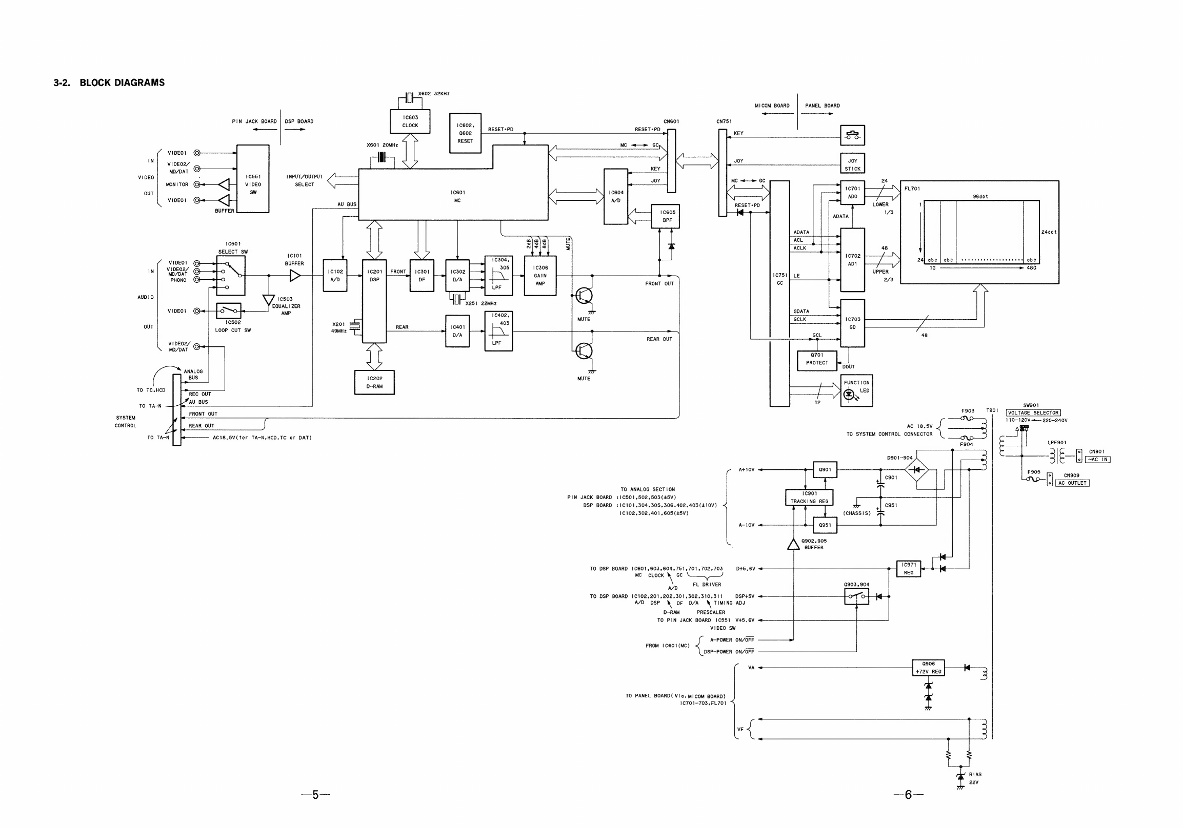
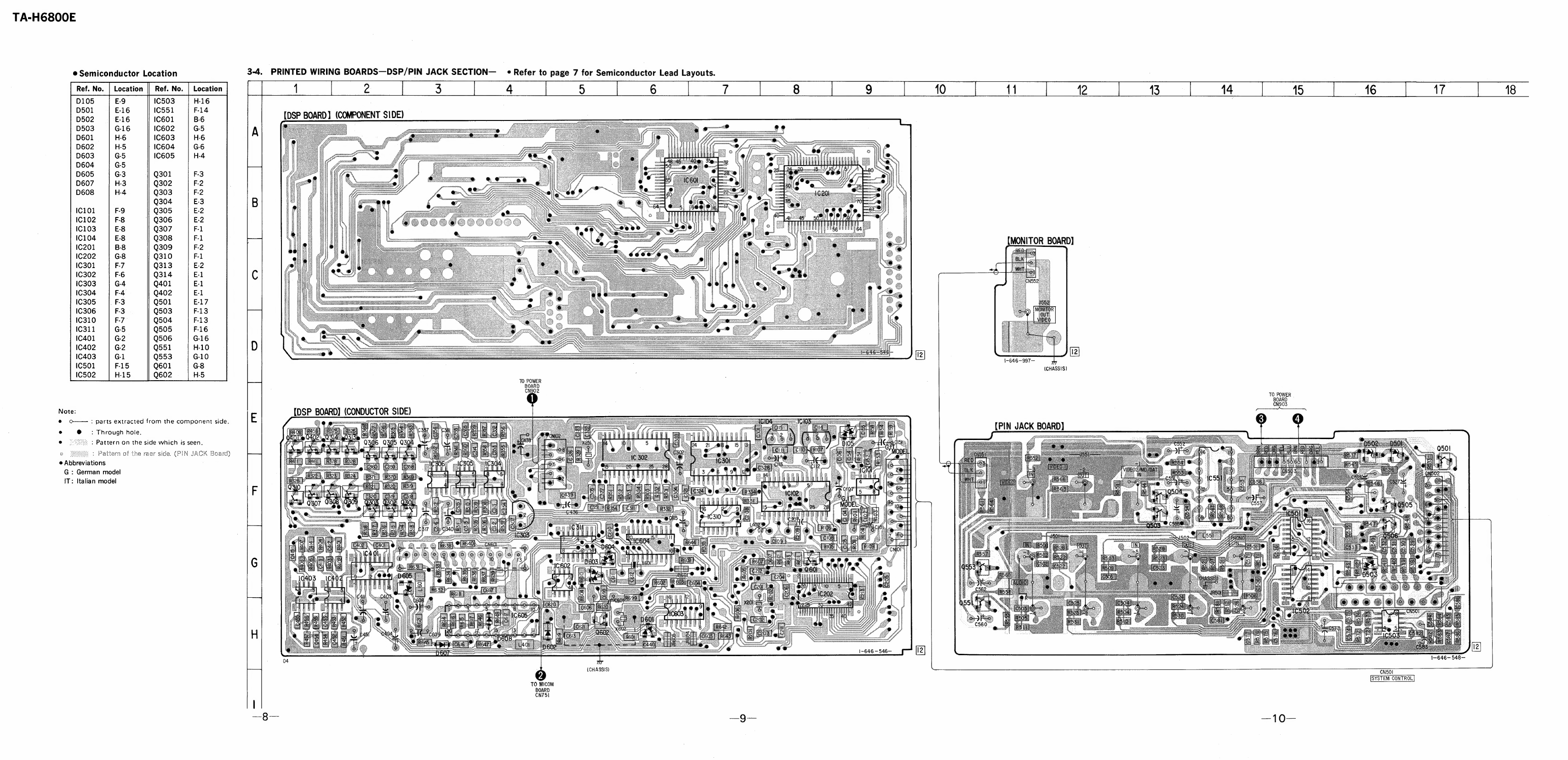
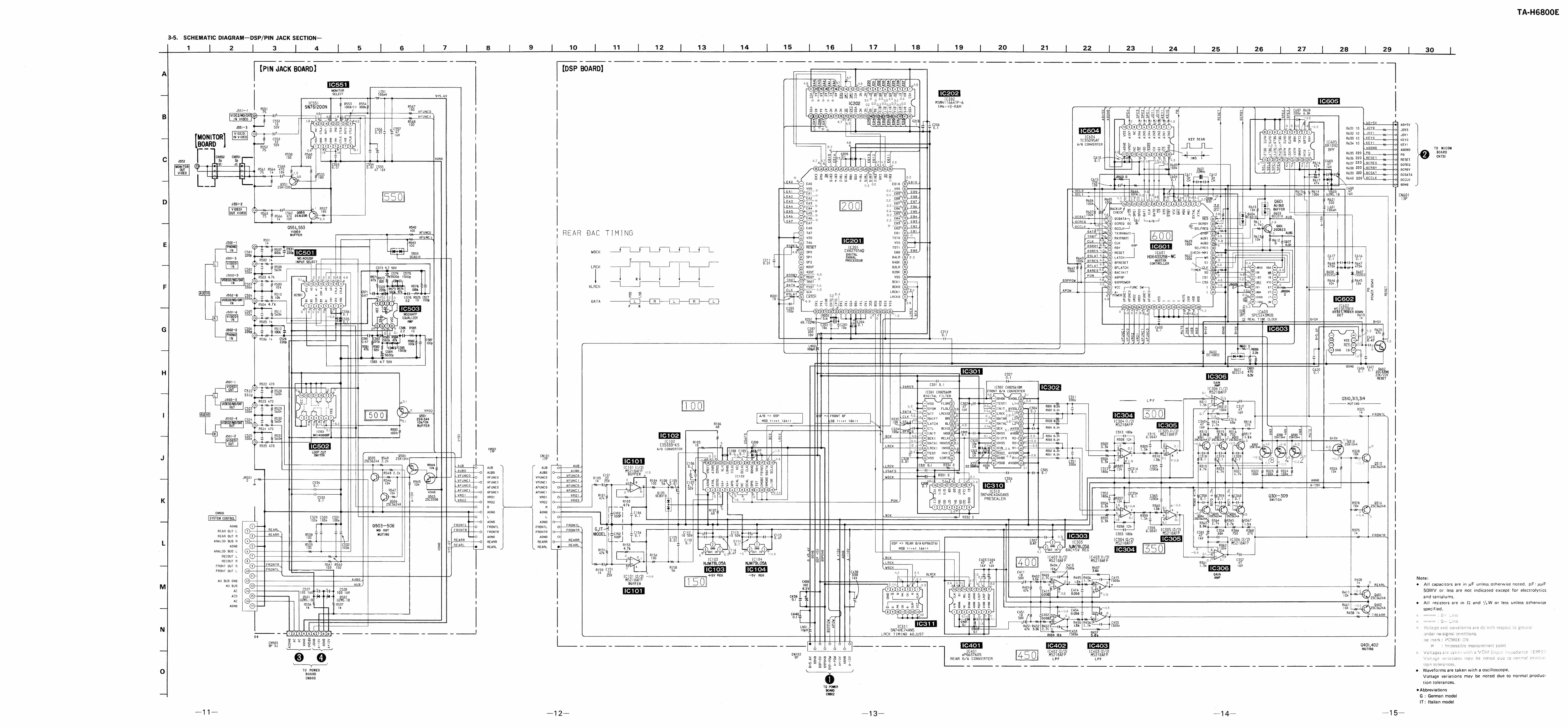
Sony TA-H6800E User manual
Other Sony Amplifier manuals

Sony
Sony TA-EX660 User manual

Sony
Sony XM-5150GSX Marketing Specifications, Connections... User manual

Sony
Sony TA-FE610R User manual

Sony
Sony XM-440EX Primary User manual

Sony
Sony TA-N9000ES User manual

Sony
Sony XM-SD46X - Stereo Power Amplifier User manual

Sony
Sony XM-ZR1252 User manual

Sony
Sony TA-AX350 User manual

Sony
Sony XM-6020 User manual

Sony
Sony EXM-302 User manual

Sony
Sony TA-FLX9W User manual

Sony
Sony TA-N55ES User manual

Sony
Sony XM-D500X Operating & Mounting User manual

Sony
Sony TA-FA5ES User manual

Sony
Sony TA-AV571 - Integrated A/v Amplifier User manual

Sony
Sony XM-1002HX User manual

Sony
Sony XM-1502SX - Stereo Power Amplifier User manual

Sony
Sony XM-GS100 User manual

Sony
Sony TA-E80ES User manual

Sony
Sony TA-DK2 User manual