manuals.online logo
Brands
  1. Home
  2. •
  3. Brands
  4. •
  5. Sony
  6. •
  7. Car Receiver
  8. •
  9. Sony XR-C102 Product guide

Sony XR-C102 Product guide

Parts for Installation and Connections
Pièces de montage et de raccordement
Montageteile und Anschlußzubehör
Componenti per installazione e collegamenti
The numbers in the list are keyed to those in the instructions.
Les numéros de la liste correspondent à ceux des instructions.
Die Nummern in der Liste sind dieselben wie im Erläuterungstext.
I numeri nella lista corrispondono a quelli riportati nelle istruzioni.
1
FM/AM
Cassette Car
Stereo
Installation/Connections
Installation/Connexions
Installation/Anschluß
Installazione/Collegamenti
3-856-659-31 (1)
XR-C102
×1×1
23
×1
Sony Corporation 1996
456
×1×1 ×1
7
×1
The release key 4is used for dismounting the unit. See the operating instructions manual for details.
La clé de déverrouillage 4est nécessaire pour démonter l’appareil. Consulter le mode d’emploi pour
plus de détails.
Zum Ausbau des Geräts wird der Freigabeschlüssel 4benötigt. Einzelheiten entnehmen Sie bitte der
Bedienungsanleitung.
La chiave di rilascio 4è usata per smontare l’apparecchio. Per dettagli, fare riferimento al manuale
d’uso.
Caution
•This unit is designed for negative ground
12 V DC operation only.
•Before making connections, disconnect the
ground terminal of the car battery to avoid short
circuits.
•Connect the yellow and red power input leads
only after all other leads have been connected.
•Be sure to connect the red power input lead to
the positive 12 V power terminal which is
energized when the ignition key is in the
accessory position.
•Run all ground wires to a common ground
point.
Précautions
•Cet appareil est conçu pour fonctionner sur
courant continu de 12 V avec masse négative.
•Avant d’effectuer les connexions, débrancher la
borne de terre de la batterie du véhicule pour
éviter tout court-circuit.
•Brancher les fils d’entrée d’alimentation jaune et
rouge seulement après avoir terminé tous les
autres branchements.
•Veiller à ne pas raccorder le fil rouge d’entrée
d’alimentation à la borne positive de 12 V qui est
alimentée quand la clé de contact est sur la
position accessoire.
•Rassembler tous les fils de terre en un point
de masse commun.
Vorsicht
•Dieses Gerät ist ausschließlich für eine negativ
geerdete 12-V-Autobatterie bestimmt.
•Trennen Sie vor dem Anschließen des Geräts die
Erdungsklemme der Batterie ab, um einen
Kurzschluß zu vermeiden.
•Schließen Sie das gelbe und rote
Stromversorgungskabel erst an, wenn alle
anderen Kabel bereits angeschlossen sind.
•Leiten Sie das rote Stromversorgungskabel an
einen positiven 12-V-Kontakt, an dem Spannung
anliegt, wenn sich das Zündschloß in der
Position I bzw. ACC (Position vor der
Zündposition) befindet.
•Schließen Sie alle Erdungskabel an einen
gemeinsamen Massepunkt an.
Attenzione
•Questo apparecchio è stato progettato per l’uso
solo a 12 V CC con massa negativa.
•Prima di eseguire i collegamenti, scollegare il
terminale di massa della batteria dell’auto per
evitare cortocircuiti.
•Collegare i cavi di ingresso alimentazione rosso
e giallo solo dopo aver collegato tutti gli altri
cavi.
•Assicurarsi di collegare il cavo rosso di ingresso
alimentazione al terminale di alimentazione 12 V
positivo, che è sotto tensione quando la chiave di
accensione è in posizione accessoria.
•Portare tutti i cavi di massa a un punto di
massa comune.
Connections Connexions CollegamentiAnschluß
Reset Button
When the installation and connections are over, be
sure to press the reset button with a ball-point pen
etc.
Rücksetztaste
Nach der Installation und dem Anschluß muß die
Rücksetztaste mit einem Kugelschreiber o.ä.
gedrückt werden.
Touche de réinitialisation
Quand l’installation et les connexions sont
terminées, appuyer sur la touche de
réinitialisation avec un stylo bille ou un objet
pointu.
Pulsante di azzeramento
Dopo avere terminato l’installazione e i
collegamenti, assicurarsi di premere il pulsante di
azzeramento con la punta di una penna a sfera.
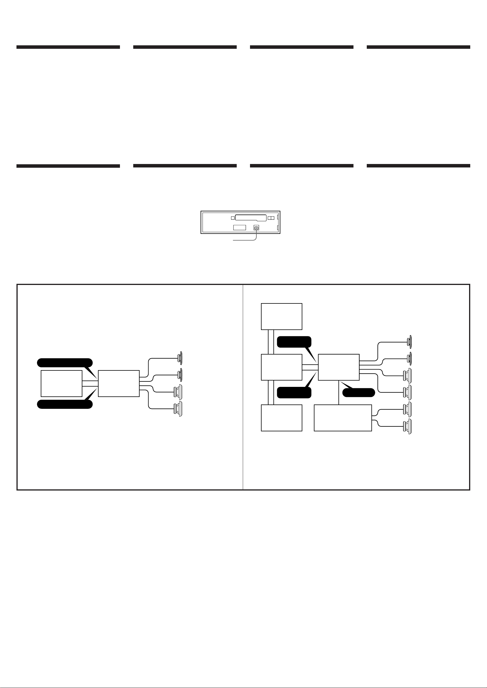
Schema di collegamentoAnschlußdiagrammSchémas de connexionConnection Diagram
Example 1/Exemple 1/Beispiel 1/Esempio 1 Example 2/Exemple 2/Beispiel 2/Esempio 2
Reset button
Touche de réinitialisation
Rücksetztaste
Pulsante di azzeramento
Rear speakers
Haut-parleurs arrière
Hecklautsprecher
Diffusori posteriori
Front speakers
Haut-parleurs avant
Frontlautsprecher
Diffusori anteriori
Power amplifier
Amplificateur de puissance
Endverstärker
Amplificatore di potenza
Rear speakers
Haut-parleurs arrière
Hecklautsprecher
Diffusori posteriori
Source selector
Sélecteur de source
Signalquellenwähler
Selettore di fonte
CD Changer
Changeur de CD
CD-Wechsler
Cambia CD
CD Changer
Changeur de CD
CD-Wechsler
Cambia CD
LINE OUT
XR-C102
BUS
CONTROL IN
BUS
AUDIO IN
Front speakers
Haut-parleurs avant
Frontlautsprecher
Diffusori anteriori
Rear speakers
Haut-parleurs arrière
Hecklautsprecher
Diffusori posteriori
XR-C102
BUS IN AUDIO
BUS IN CONTROL
CD Changer
Changeur de CD
CD-Wechsler
Cambia CD
Note sui cavi di collegamento
Ilcavo(blu)dicontrollodell’antennaforniscealimentazione
CD12quandosiaccendeilsintonizzatore.
Note sul collegamento dei diffusori
• Usarediffusoridiimpedenzacompresatra4e8ohmecon
capacitàdipotenzaadeguata,altrimentipotrebbero
danneggiarsi.
• Noncollegareiterminalidelsistemadiffusorialtelaio
dell’autoenoncollegareiterminalideldiffusoredestroa
quellideldiffusoresinistro.
• Noncollegareidiffusoriinparallelo.
• Noncollegarediffusoriattivi(conamplificatoriincorporati)
aiterminalideidiffusoridell’apparecchio,perchéidiffusori
attivipotrebberodanneggiarsi.Collegaresolodiffusori
passiviaquestiterminali.
Avvertenza
Sel’antennachecollegal’apparecchioalcavodialimentazione
in dotazione 5nonhala scatola direlè, l’antenna. sipuò
danneggiare.
Hinweise zu den Steuerleitungen
DieSteuerleitung(blau)derMotorantennelieferteine
Gleichspannungvon12Volt,wennSiedasGeräteinschalten.
Hinweise zum Lautsprecheranschluß
• VerwendenSieLautsprechermiteinerImpedanzzwischen4
und8OhmundausreichenderBelastbarkeit.Ansonsten
könnendieLautsprecherbeschädigtwerden.
• VerbindenSiedieLautsprecheranschlüssenichtmitdem
Wagenchassis,undverbindenSieauchnichtdieAnschlüsse
desrechtenmitdenendeslinkenLautsprechers.
• SchließenSieniemalsLautsprecherparallelan.
• AndieLautsprecheranschlüssedürfennur
Passivlautsprecherangeschlossenwerden.SchließenSieauf
keinenFallAktivlautsprecher(miteingebautemVerstärker)
an,dadiesebeschädigtwerdenkönnten.
Warnung
WennSieeineMotorantenneohneRelaiskästchenverwenden,
kanndurchAnschließendiesesGerätsmitdemmitgelieferten
Netzverbindungskabels5dieAntennebeschädigtwerden.
Remarque sur les fils de contrôle
Lefildecommande(bleu)del’antenneélectriquefournitune
tensionde12VCClorsquevousmettezl’appareilsoustension.
Remarques sur la connexion des haut-parleurs
• Utiliserdeshaut-parleursavecuneimpédancede4à8ohms
etquipeuventsupporterl’alimentationfourniesinonils
risqueraientd’êtreendommagés.
• Nepasconnecterlesbornesdusystèmedehaut-parleurau
châssisdelavoitureetnepasraccorderlesbornesduhaut-
parleurdroitauxbornesduhaut-parleurgauche.
• Nepasessayerdeconnecterleshaut-parleursenparallèle.
• Nepasconnecterd’enceintesacoustiquesactives(avec
amplificateursintégrés)auxbornesd’enceintesdecet
appareilpouréviterdelesendommager.Veilleràraccorder
desenceintespassives.
Avertissement
Sivousdisposezd‘uneantenneélectriquesansboîtierderelais,
lebranchementdecetappareilaumoyenducordon
d‘alimentationfourni5risqued‘endommagerl‘antenne.
Note on the control leads
Thepowerantennacontrollead(blue)supplies12VDCpower
whenyouturnontheunit.
Notes on speaker connections
• Usespeakerswithanimpedanceof4to8ohms,andwith
adequatepowerhandlingcapacities.Otherwise,thespeakers
maybedamaged.
• Donotconnecttheterminalsofthespeakersystemtothecar
chassis,anddonotconnecttheterminalsoftherightspeaker
withthoseoftheleftspeaker.
• Donotconnectthespeakersinparallel.
• Donotconnectanyactivespeakers(withbuilt-inamplifiers)
tothespeakerterminalsoftheunit.Doingsomaydamage
theactivespeakers.Therefore,besuretoconnectpassive
speakerstotheseterminals.
Warning
Ifyouhaveapowerantennawithoutarelaybox,connecting
thisunitwiththesuppliedpowerconnectingcord5may
damagetheantenna.
Forconnectingtwo changers,thesourceselectorXA-C30(optional)andtheBUScable RC-61 (1m)or
RC-62(2m)(optional)arenecessary.
Pourleraccordementdedeux changeurs,vousdevezutiliserlesélecteurdesource XA-C30(optionnel)et
lecâble BUS RC-61 (1 m)ou RC-62(2 m)(optionnels).
ZumAnschlußvonzwei WechslernwerdenderSignalquellenwählerXA-C30(getrennterhältlich)und
dasBUS-KabelRC-61(1m)oderRC-62(2m)(getrennt erhältlich) benötigt.
Sesicollegano due cambia CD, utilizzareilselettoredi fonte XA-C30(opzionali)eil cavo BUSRC-61(1m) o
RC-62(2m)(opzionali).
Connections Example Connexions de l’exemple Anschlußbeispiel Collegamenti per l’esempio
RCA pin cord (RC-63 (1 m), RC-64 (2 m) or RC-65 (5 m)) (not supplied)
Cordon à broche RCA (RC-63 (1 m), RC-64 (2 m) ou RC-65 (5 m)) (non fournis)
RCA-Kabel (RC-63 (1 m), RC-64 (2 m) oder RC-65 (5 m)) (nicht mitgeliefert)
Cavo a piedini RCA (RC-63 (1 m), RC-64 (2 m) o RC-65 (5 m)) (non in dotazione)
5
Pin
Broche
Stift
Pin
5
6
7
8
Pin
Broche
Stift
Pin
1
2
3
4
Colour
Couleur
Farbe
Colore
Function
Fonction
Funktion
Funzione
+; Speaker, Rear, Right
+; haut-parleur, arrière, droit
+: Lautsprecher hinten rechts
+:Altoparlante, posteriore, destro
–; Speaker, Rear, Right
–; haut-parleur, arrière, droit
–: Lautsprecher hinten rechts
–: Altoparlante, posteriore, destro
+; Speaker, Front, Right
+; haut-parleur, avant, droit
+: Lautsprecher vorne rechts
+:
Altoparlante, anteriore, destro
–; Speaker, Front, Right
–; haut-parleur, avant, droit
–: Lautsprecher vorne rechts
–: Altoparlante, anteriore, destro
Function
Fonction
Funktion
Funzione
+; Speaker, Front, Left
+; haut-parleur, avant, gauche
+: Lautsprecher vorne links
+: Altoparlante, anteriore, sinistro
–; Speaker, Front, Left
–; haut-parleur, avant, gauche
–: Lautsprecher vorne links
–: Altoparlante, anteriore, sinistro
+; Speaker, Rear, Left
+; haut-parleur, arrière, gauche
+: Lautsprecher hinten links
+: Altoparlante, posteriore, sinistro
–; Speaker, Rear, Left
–; haut-parleur, arrière, gauche
–: Lautsprecher hinten links
–: Altoparlante, posteriore, sinistro
Colour
Couleur
Farbe
Colore
Purple
Mauve
Violett
Viola
White
Blanc
Weiß
Blanco
Gray
Gris
Grau
Grigio
Green
Vert
Grün
Verde
Negativepolaritypositions2,4,6and8havestripedcords.
Lespositionsdepolariténégative2,4,6et8sontdotéesdecordonsrayés.
AndennegativgepoltenPositionen(2,4,6und8)befindensichgestreifteAdern.
Leposizioniapolaritànegativa2,4,6e8hannocavispelati.
Function
Fonction
Funktion
Funzione
continuous power supply
alimentation continue
permanente Stromversorgung
alimentazione continua
power antenna control
antenne électrique
elektronische Antenne
antenna elettrica
Pin
Broche
Stift
Pin
7
8
Colour
Couleur
Farbe
Colore
Red
Rouge
Rot
Rosso
Black
Noir
Schwarz
Nero
Function
Fonction
Funktion
Funzione
switched power supply
alimentation commutée
geschaltete Stromversorgung
alimentazione a scatto
ground
masse
Masse
terra
Positions1, 2, 3and6 donothave pins.
Lespositions1,2,3et6necomportentpasdebroche.
AnPosition1,2, 3und6befindensich keine Stifte.
Leposizioni 1, 2,3 e 6non hanno pin.
Colour
Couleur
Farbe
Colore
Yellow
Jaune
Gelb
Giallo
Blue
Bleu
Blau
Blu
Pin
Broche
Stift
Pin
4
5
Max. supply current 0.3 A
Courant max. fourni 0,3 A
max. Versorgungsstrom 0,3 A
Alimentazione massima fornita 0,3 A
Rear speakers
Haut-parleurs arrière
Hecklautsprecher
Diffusori posteriori
from car antenna
de l’antenne de la voiture
von Autoantenne
dall’antenna dell’auto
AMP REM
Blue/white striped
Rayé bleu/blanc
blau-weiß gestreift
A strisce blu e bianche
7135
8246
1357
2468
1357
2468
7135
8246
CD changer
Changeur de CD
CD-Wechsler
Cambiatore CD
Fuse (10 A)
Fusible (10 A)
Sicherung (10 A)
Fusibile (10 A)
to a car's auxiliary power connector
vers un connecteur d’alimentation auxiliaire de la voiture
an Hilfsstromanschluß im Auto
Verso un connettore di alimentazione ausiliaria dell’auto
WARNING
Auxiliary power connectors may vary depending on the car. Be sure to check the
power connection diagram sheet supplied with the unit. Improper connections
may damage your car. If the supplied power connecting cord can not be used with
your car, consult your nearest Sony dealer.
AVERTISSEMENT
Le connecteur d’alimentation auxiliaire peut varier suivant le type de voiture.
Vérifiez le schéma du connecteur d’alimentation auxiliaire de votre voiture pour
vous assurer que les connexions correspondent. Un raccordement incorrect peut
occasionner des dommages à votre voiture. Si le cordon d’alimentation fourni ne
peut être utilisé avec votre voiture, consultez votre revendeur Sony.
VORSICHT
Die Hilfsstromanschlüsse können je nach Fahrzeugtyp unterschiedlich sein. Sehen
Sie im Hilfsstromanschlußdiagramm für Ihr Fahrzeug nach, wie die Verbindungen
ordnungsgemäß vorgenommen werden müssen. Fehlerhafte Verbindungen
können zu Schäden an Ihrem Fahrzeug führen. Wenn das mitgelieferte
Netzverbindungskabel nicht für den Einsatz in Ihrem Fahrzeug geeignet ist,
wenden Sie sich bitte an Ihren Sony-Händler.
ATTENZIONE
I connettori di alimentazione ausiliari possono variare a seconda del tipo di auto.
Assicurarsi di controllare il diagramma per il collegamento dell’alimentazione in
dotazione con l’apparecchio. Collegamenti non eseguiti correttamente potrebbero
danneggiare l’auto. Se il cavo di collegamento dell’alimentazione in dotazione non
può essere utilizzato con la vostra auto, consultare il rivenditore Sony più vicino. to a car's speaker connector
vers un connecteur de haut-parleur de la voiture
an Lautsprecheranschluß im Auto
verso un connettore del diffusore dell'auto
BUS CONTROL IN
BUS AUDIO IN
LINE OUT
Power amplifier
Amplificateur de puissance
Endverstärker
Amplificatore di potenza
BUS cable (supplied to CD changer)
Câble BUS (fourni avec le changeur CD)
BUS-Kabel (mit CD-Wechsler geliefert)
Cavo BUS (in dotazione al cambiatore CD)
RCA pin cord (supplied to CD changer)
Cordon à broche RCA (fourni avec le changeur CD)
RCA-Kabel (mit CD-Wechsler geliefert)
Cavo a terminali RCA (in dotazione al cambiatore CD)
Precautions
•Choose the installation location carefully so that
the unit will not hamper the driver during
driving.
•Avoid installing the unit where it would be
subject to high temperatures, such as from direct
sunlight or hot air from the heater, or where it
would be subject to dust, dirt or excessive
vibration.
•Use only the supplied mounting hardware for a
safe and secure installation.
Mounting angle adjustment
Adjust the mounting angle to less than 20°.
Précautions
•Choisir soigneusement l’emplacement de
l’installation, pour que l’appareil ne gêne pas la
conduite.
•Eviter d’installer l’appareil dans un endroit
exposé à des températures élevées, comme en
plein soleil ou à proximité d’une bouche d’air
chaud, ou à de la poussière, saleté ou vibrations
violentes.
•Pour garantir un montage sûr, n’utiliser que le
matériel fourni.
Réglage de l’angle de montage
Ajuster l’inclinaison à un angle inférieur à 20°.
Vorsichtsmaßnahmen
•Wählen Sie den Einbauort sorgfältig so aus, daß
das Gerät den Fahrer beim Lenken des
Fahrzeugs nicht behindert.
•Bauen Sie das Gerät so ein, daß es keinen hohen
Temperaturen (keinem direkten Sonnenlicht,
keiner Warmluft von der Heizung), keinem
Staub, keinem Schmutz und keinen starken
Vibrationen ausgesetzt ist.
•Für eine sichere Befestigung verwenden Sie stets
nur die mitgelieferten Montageteile.
Hinweis zum Montagewinkel
Das Gerät sollte in einem Winkel von weniger als
20° montiert werden.
Installation Installation Installation Installazione
Precauzioni
•Scegliere con attenzione il luogo di montaggio
dell’apparecchioin, in modo che non interferisca
con le normali operazioni di guida del
conducente.
•Evitare di installare l’apparecchio dove sia
soggetto ad alte temperature, come da
esposizione alla luce solare diretta o al getto di
aria calda dell’ impianto di riscaldamento, o
dove possa essere soggetto a polvere, sporco e
vibrazioni eccessive.
•Usare solo il materiale di montaggio in
dotazione per un’installazione stabile e sicura.
Regolazione dell’angolo di montaggio
Regolare l’angolo di montaggio in modo che sia
inferiore a 20°.
Come staccare e attaccare il
pannello anteriore
Prima di installare l’apparecchio, staccare il
pannello anteriore.
Per staccare
Premere il tasto RELEASE per aprire il pannello
anteriore, quindi spostarlo leggermente verso
sinistra e poi tirarlo verso l’esterno.
Per attaccare
Allineare le parti Ae Be spingere il pannello
anteriore fino a udire uno scatto.
Abnehmen und Anbringen der
Frontplatte
Nehmen Sie die Frontplatte vor dem Einbau
des Geräts ab.
Abnehmen
Drücken Sie die RELEASE-Taste zum Lösen der
Frontplatte. Schieben Sie die Frontplatte etwas
nach links, und ziehen Sie sie dann auf sich zu
heraus.
Anbringen
Richten Sie Teil Aan Teil Baus, und drücken Sie
die Frontplatte fest, so daß sie mit einem Klicken
einrastet.
Retrait et pose de la façade
Avant d’installer l’appareil, déposer la façade.
Retrait
Appuyer sur la touche RELEASE pour ouvrir la
façade. Faites-la ensuite glisser légèrement vers la
gauche et enlevez-la en tirant vers vous.
Pose
Aligner les points Aet B, puis pousser la façade
jusqu’au déclic.
How to Detach and Attach the
Front Panel
Before installing the unit, detach the front
panel.
To detach
Press the RELEASE button to open up the front
panel. Then slide the front panel a little to the left,
and pull it off towards you.
To attach
Align the parts Aand B, and push the front
panel until it clicks.
To detach
Retrait
Abnehmen
Per staccare
To attach
Pose
Anbringen
Per attaccare
RELEASE button
Touche RELEASE
RELEASE-Taste
Tasto RELEASE
Mounting Example
Installation in the dashboard
Einbaubeispiel
Installation im Armaturenbrett
Esempio di montaggio
Installazione sul cruscotto
Exemple de montage
Installation dans le tableau de bord
31
Bend these claws, if necessary.
Si nécessaire, plier ces griffes.
Falls erforderlich, die Klemmen hochbiegen.
Piegare questi morsetti se necessario
Dashboard
Tableau de bord
Armaturenbrett
Cruscotto
Fire wall
Paroi ignifuge
Motorraumtrennwand
Parete tagliafiamma
2
Note for Connecting
If there is alternator noise (a whining sound
when raising engine speed), ground the master
unit by connecting it to a metal point of the car
with the supplied chassis ground cord 7.
Connect the ground cord to the master unit
with part 2as shown in the illustration. (In
case you do not use part 2, take screw 6
instead.)
Note per il collegamento
Se si riscontra un disturbo dell’alternatore (un
rumore acuto quando si accelera) è necessario
mettere a terra l’unità principale collegandola
ad un punto metallico dell’auto mediante il
cavo di messa a terra del telaio 7in dotazione.
Collegare il cavo di messa a terra all’unità
principale con la parte 2come illustrato nella
figura. (Nel caso in cui non si disponga della
parte 2, utilizzare una vite 6.)
Hinweis zum Anschluß
Bei Störgeräuschen des Wechselstromgenerators
(Heulton bei ansteigender Motorleistung) erden
Sie das Hauptgerät, indem Sie es mit dem
mitgelieferten Massekabel 7mit einem Metallteil
des Autos verbinden. Verbinden Sie das
Massekabel wie in der Abbildung dargestellt über
Teil 2mit dem Hauptgerät. (Wenn Sie Teil 2
nicht verwenden, nehmen Sie statt dessen
Schraube 6.)
Remarque sur le raccordement
Si l’alternateur génère des interférences (pleurage
lorsque le régime moteur augmente), reliez
l’appareil principal à la masse en le raccordant à
un point métallique de la voiture au moyen du fil
de masse pour châssis 7fourni. Raccordez le fil
de masse à l’appareil principal au moyen de la
pièce 2comme indiqué dans l’illustration. (Si
vous n’utilisez pas la pièce 2, utilisez la pièce 6.)
182 mm
53 mm
1
2
3
2
7
to a metal point of the car
à un point métallique de la voiture
an eine metallene Stelle am Auto
a un punto metallico dell’auto
BA

Other manuals for XR-C102

1

Other Sony Car Receiver manuals

Sony CDX-S22 User manual

Sony

Sony CDX-S22 User manual

Sony MDX-C7900 User manual

Sony

Sony MDX-C7900 User manual

Sony CXS-GT46F - Fm/am Compact Disc Player Product guide

Sony

Sony CXS-GT46F - Fm/am Compact Disc Player Product guide

Sony MDX-C8500R User manual

Sony

Sony MDX-C8500R User manual

Sony DSX-S100 Product guide

Sony

Sony DSX-S100 Product guide

Sony CDX-4180FP - Fm/am Compact Disc Changer... User manual

Sony

Sony CDX-4180FP - Fm/am Compact Disc Changer... User manual

Sony CDX-1150 - Compact Disc Player Product guide

Sony

Sony CDX-1150 - Compact Disc Player Product guide

Sony CDX-GT420U User manual

Sony

Sony CDX-GT420U User manual

Sony CDX-3100 User manual

Sony

Sony CDX-3100 User manual

Sony AVD-S50ES - Single Disc Dvd/sacd™/cd... User guide

Sony

Sony AVD-S50ES - Single Disc Dvd/sacd™/cd... User guide

Sony CDX-4180R User manual

Sony

Sony CDX-4180R User manual

Sony XAV-AX5650 Reference guide

Sony

Sony XAV-AX5650 Reference guide

Sony XR-2500 User manual

Sony

Sony XR-2500 User manual

Sony CDX-C4840R User manual

Sony

Sony CDX-C4840R User manual

Sony MEX-BT3700U User manual

Sony

Sony MEX-BT3700U User manual

Sony XAV-3500 Reference guide

Sony

Sony XAV-3500 Reference guide

Sony CDX-CA890X User manual

Sony

Sony CDX-CA890X User manual

Sony XDP-MU110 Product guide

Sony

Sony XDP-MU110 Product guide

Sony CDX-L490EE User manual

Sony

Sony CDX-L490EE User manual

Sony CDX-3900R User manual

Sony

Sony CDX-3900R User manual

Sony XR-C5110R User manual

Sony

Sony XR-C5110R User manual

Sony CDX-GT61UI - Cd Receiver With Ipod... User manual

Sony

Sony CDX-GT61UI - Cd Receiver With Ipod... User manual

Sony CDX-GT472UM User manual

Sony

Sony CDX-GT472UM User manual

Sony CDX-GT66UPW User manual

Sony

Sony CDX-GT66UPW User manual

Popular Car Receiver manuals by other brands

Blaupunkt Monterey CDM83 Owner's record

Blaupunkt

Blaupunkt Monterey CDM83 Owner's record

JBL Legend CP100 user manual

JBL

JBL Legend CP100 user manual

Pioneer DEH-P7700MP - In-Dash CD/MP3/WMA/WAV/iTunes AAC Car Stereo... installation manual

Pioneer

Pioneer DEH-P7700MP - In-Dash CD/MP3/WMA/WAV/iTunes AAC Car Stereo... installation manual

Advent AMM10N Installation and operation manual

Advent

Advent AMM10N Installation and operation manual

Alpine HDA-5460 owner's manual

Alpine

Alpine HDA-5460 owner's manual

Panasonic CQ-DFX600N Service manual

Panasonic

Panasonic CQ-DFX600N Service manual

Aiwa CT-Z109 Service manual

Aiwa

Aiwa CT-Z109 Service manual

JVC HA KD-S600 instructions

JVC

JVC HA KD-S600 instructions

Kenwood DPX-8030MD Service manual

Kenwood

Kenwood DPX-8030MD Service manual

Dual Electronics Corporation XDVD8182 Installation & owner's manual

Dual Electronics Corporation

Dual Electronics Corporation XDVD8182 Installation & owner's manual

Pioneer DEH-M6067ZH Service manual

Pioneer

Pioneer DEH-M6067ZH Service manual

Volkswagen RMT200 User handbook

Volkswagen

Volkswagen RMT200 User handbook

Pioneer DEH-2050MP/XN/ES Service manual

Pioneer

Pioneer DEH-2050MP/XN/ES Service manual

Kenwood Z919 instruction manual

Kenwood

Kenwood Z919 instruction manual

JVC KS-U15K instructions

JVC

JVC KS-U15K instructions

Jensen VM9116 installation guide

Jensen

Jensen VM9116 installation guide

Crutchfield 000SRADIG user guide

Crutchfield

Crutchfield 000SRADIG user guide

Clarion ADZ625 owner's manual

Clarion

Clarion ADZ625 owner's manual

manuals.online logo
manuals.online logoBrands
  • About & Mission
  • Contact us
  • Privacy Policy
  • Terms and Conditions

Copyright 2025 Manuals.Online. All Rights Reserved.