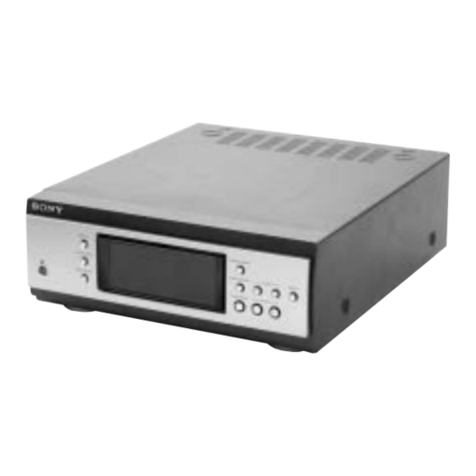
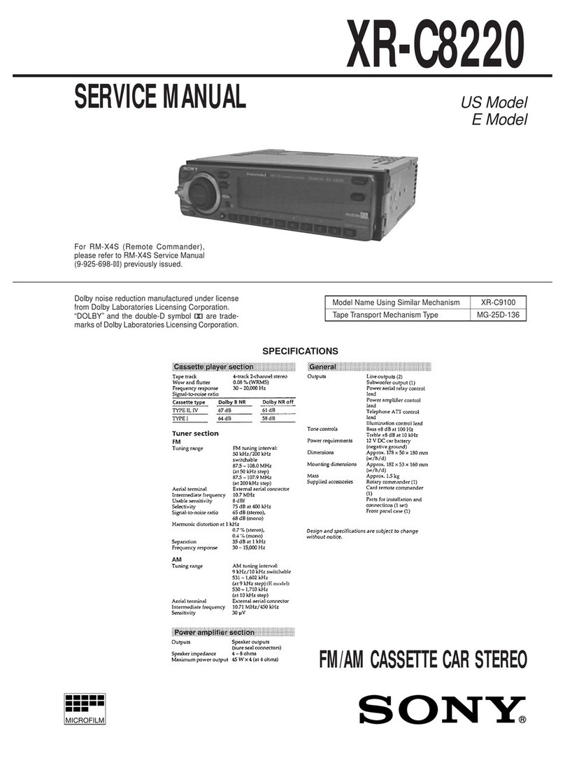
Sony XR-C540RDS User manual

9-925-543-12 Sony Corporation
2001F0500-1 e Vehicle Company
C2001.6 ShinagawaTec Service Manual Production Group
XR-C540RDS
AEP Model
UK Model
SERVICE MANUAL
FM/MW/LW CASSETTE CAR STEREO
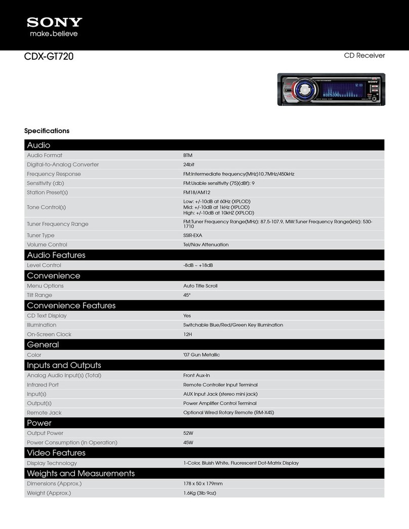
SPECIFICATIONS
Model Name Using Similar Mechanism NEW
Tape Transport Mechanism Type
MG-52B-136
For RM-X2S (Remote Commander),
please refer to RM-X2S/X3S Service
Manual (9-960-039-S) previously issued.
Dolby noise reduction manufactured under license
from Dolby Laboratories Licensing Corporation.
“DOLBY”andthe double-Dsymbol;aretrademarks
of Dolby Laboratories Licensing Corporation.
Cassette player section
Tape track 4-track 2-channel stereo
Wow and flutter 0.08% (WRMS)
Frequency response 30 – 18,000 Hz
Signal-to-noise ratio 64 dB (Dolby B NR)
58 dB (Dolby NR off)
Tuner section
FM
Tuning range 87.5 – 108.0 MHz
Antenna terminal External antenna connector
Intermediate frequency 10.7 MHz
Usable sensitivity 8 dBf
Selectivity 75 dB at 400 kHz
Signal-to-noise ratio 65 dB (stereo),
70 dB (mono)
Harmonic distortion at 1 kHz 0.5% (stereo),
0.3% (mono)
Separation 35 dB at 1 kHz
Frequency response 30 – 15,000 Hz
Capture ratio 4 dB
MW/LW
Tuning range MW: 531 – 1,602 kHz
LW: 153 – 281 kHz
Antenna terminal External antenna connector
Intermediate frequency 10.71 Mhz/450 kHz
Sensitivity MW: 30 µV
LW: 50 µV
Power amplifier section
Outputs Speaker outputs
(sure seal connectors)
Speaker impedance 4 – 8 ohms
Maximum power output 35 W ×4 (at 4 ohms)
General
Outputs Power amplifier control lead
Rear line out (1)
Tone controls Bass ± 8 dB at 100 Hz
Treble ± 8 dB at 10 kHz
Power requirements 12 V DC car battery (negative ground)
Dimensions Approx. 188 ×58 ×181 mm (w/h/d)
Mounting dimensions Approx. 182 ×53 ×164 mm (w/h/d)
Mass Approx. 1.2 kg
Supplied accessories Parts for installation and connections
(1 set)
Rotary commander RM-X2S
Front panel case (1)
Design and specifications are subject to change without notice.
Ver 1.1 2001.06
w
w
w
.
x
i
a
o
y
u
1
6
3
.
c
o
m
Q
Q
3
7
6
3
1
5
1
5
0
9
9
2
8
9
4
2
9
8
T
E
L
1
3
9
4
2
2
9
6
5
1
3
9
9
2
8
9
4
2
9
8
0
5
1
5
1
3
6
7
3
Q
Q
TEL 13942296513 QQ 376315150 892498299
http://www.xiaoyu163.com

– 2 –
TABLE OF CONTENTS
1. GENERAL
Location of Controls ........................................................ 3
Setting the Clock ............................................................. 3
Using the Rotary Remote ................................................ 3
Adjusting the Sound Characteristics ............................... 4
Muting the Sound ............................................................ 4
Changing the Sound and Beep Tone................................ 4
Installation ....................................................................... 5
Connections ..................................................................... 6
2. DISASSEMBLY.......................................................... 9
3. ASSEMBLY OF MECHANISM DECK............. 11
4. MECHANICAL ADJUSTMENTS ....................... 14
5. ELECTRICAL ADJUSTMENTS
Test Mode ........................................................................ 14
Tape Deck Section ........................................................... 14
Tuner Section................................................................... 15
6. DIAGRAMS
6-1. Printed Wiring Boards –Main Section– .......................... 22
6-2. Schematic Diagram –Main Section– .............................. 25
6-3. Schematic Diagram –Panel Section–.............................. 30
6-4. Printed Wiring Board –Panel Section– ........................... 33
6-5. IC Pin Function Description ............................................ 35
7. EXPLODED VIEWS ................................................ 37
8. ELECTRICAL PARTS LIST................................ 40
SERVICING NOTES
Flexible Circuit Board Repairing
•Keep the temperature of the soldering iron around 270 ˚C dur-
ing repairing.
•Do not touch the soldering iron on the same conductor of the
circuit board (within 3 times).
•Be careful not to apply force on the conductor when soldering
or unsoldering
Notes on chip component replacement
•Never reuse a disconnected chip component.
•Notice that the minus side of a tantalum capacitor may be dam-
aged by heat.
w
w
w
.
x
i
a
o
y
u
1
6
3
.
c
o
m
Q
Q
3
7
6
3
1
5
1
5
0
9
9
2
8
9
4
2
9
8
T
E
L
1
3
9
4
2
2
9
6
5
1
3
9
9
2
8
9
4
2
9
8
0
5
1
5
1
3
6
7
3
Q
Q
TEL 13942296513 QQ 376315150 892498299
http://www.xiaoyu163.com
– 9 –
Note: Follow the disassembly procedure in the numerical order given.
SECTION 2
DISASSEMBLY
FRONT PANEL ASS’Y
1
Push the button
(release).
A
2
Remove the front panel ass’y
to the direction of the arrow
A
.
COVER ASS’Y
2
1
1
2
3
cover ass’y
w
w
w
.
x
i
a
o
y
u
1
6
3
.
c
o
m
Q
Q
3
7
6
3
1
5
1
5
0
9
9
2
8
9
4
2
9
8
T
E
L
1
3
9
4
2
2
9
6
5
1
3
9
9
2
8
9
4
2
9
8
0
5
1
5
1
3
6
7
3
Q
Q
TEL 13942296513 QQ 376315150 892498299
http://www.xiaoyu163.com
– 10 –
5
screw
(PTT2.6
×
6)
6
mechanism deck (MG-25B-136)
4
flexible flat cable
(CN301)
1
three screws
(PTT2.6
×
8)
1
three screws
(PTT2.6
×
8)
2
sub panel
3
connector
(CN302)
MAIN BOARD, HEAT SINK 4
seven screws
(PTT2.6
×
8)
2
two ground point
screws
1
two screws
(PTT2.6
×
8)
3
main board
5
heat sink
1
screw
(PTT2.6
×
8)
SUB PANEL, MECHANISM DECK (MG-25B-136)
w
w
w
.
x
i
a
o
y
u
1
6
3
.
c
o
m
Q
Q
3
7
6
3
1
5
1
5
0
9
9
2
8
9
4
2
9
8
T
E
L
1
3
9
4
2
2
9
6
5
1
3
9
9
2
8
9
4
2
9
8
0
5
1
5
1
3
6
7
3
Q
Q
TEL 13942296513 QQ 376315150 892498299
http://www.xiaoyu163.com

– 11 –
Note: Follow the assembly procedure in the numerical order given.
2
Install the hanger onto
two claws of the housing.
1
Install the catch to the hanger.
7
Hold the hanger by bending the claw.
A
part
B
part
C
part
D
part
8
Hold the hanger by
bending the claw.
3
Put the housing
under
A
part.
4
Fit claw on
B
part.
6
Fit projection on
D
part.
5
Fit projection on
C
part.
hanger
HOUSING
housing
SECTION 3
ASSEMBLY OF MECHANISM DECK
2
Move the arm (suction) in the arrow
direction and fit on projection.
1
Fit the arm (suction) on the shaft.
projection
ARM (SUCTION)
w
w
w
.
x
i
a
o
y
u
1
6
3
.
c
o
m
Q
Q
3
7
6
3
1
5
1
5
0
9
9
2
8
9
4
2
9
8
T
E
L
1
3
9
4
2
2
9
6
5
1
3
9
9
2
8
9
4
2
9
8
0
5
1
5
1
3
6
7
3
Q
Q
TEL 13942296513 QQ 376315150 892498299
http://www.xiaoyu163.com
– 12 –
1
Fit the lever (LDG-A) on
shafts
A
–
C
and install it.
shaft
A
shaft
C
4
type-E stop ring 2.0
shaft
A
shaft
C
LEVER (LDG-A) / (LDG-B)
shaft
B
GEAR (LDG-FT)
3
Align hole in the gear (LDG-D)
with hole in the lever (LDG-A).
gear (LDG-FB)
hole
gear (LDG-D)
lever (LDG-A)
2
Move the lever (LDG-B)
in the arrow direction.
1
tension spring (lever LDG)
4
gear (LDG-FT)
5
polyethylene washer
hole
2
Pull the lever in the
arrow direction.
3
Fit the lever (LDG-B) on
shafts
A
and
C
and
install it.
w
w
w
.
x
i
a
o
y
u
1
6
3
.
c
o
m
Q
Q
3
7
6
3
1
5
1
5
0
9
9
2
8
9
4
2
9
8
T
E
L
1
3
9
4
2
2
9
6
5
1
3
9
9
2
8
9
4
2
9
8
0
5
1
5
1
3
6
7
3
Q
Q
TEL 13942296513 QQ 376315150 892498299
http://www.xiaoyu163.com

– 14 –
See the adjustment location from on page 17 for the
adjustment.
0 dB=0.775 VTAPE DECK SECTION
Tape Speed Adjustment
Procedure:
1. Put the set into the FWD PB mode.
Speed checker Frequency counter
–1.5 to +2.5% 2,955 to 3,075 Hz
Specification: Constant speed
Adjustment Location: See page 17.
DOLBY Level Adjustment
Setting:
Preset 3 (DOLBY) button : OFF
SEL (VOL) button : Maximum
set +–
test tape
WS-48A
(3 kHz, 0 dB)
speaker out terminal
4
Ω
speed checker
or
frequency counte
r
set
test tape
P-4-D400
(400 Hz, 0 dB)
MAIN board
TP (DOLBY)
+
–
level mete
r
L-CH
R-CH
Pocedure:
1. Put the set into the FWD PB mode.
2. Adjust RV401 (L-CH) and RV301 (R-CH) so that level meter
reading is – 6 ± 1 dB (0.35 to 0.43 V).
3. Select the REV play mode, and confirm that level meter read-
ing is within the specification given above.
Adjustment Location: See page 17.
SECTION 4
MECHANICAL ADJUSTMENTS
1. Clean the following parts with a denatured-alcohol-moistene
swab: playback head pinch roller
rubber belt capstan
idlers
2. Demagnetize the playback head with a head demagnetizer.
3. Do not use a magnetized screwdriver for the adjustments.
4. After the adjustments, apply suitable locking compound to the
parts adjusted.
5. The adjustments should be performed with the power supply
voltage unless otherwise noted.
•Torque Measurement
Mode Torqu Meter Meter Reading
Forward CQ-102C 30 – 65 g•cm
(0.42 – 0.90 oz•inch)
Forward CQ-102C 0.5 – 4.5 g•cm
Back Tension (0.01 – 0.06 oz•inch)
Reverse CQ-102RC 30 – 65 g•cm
(0.42 – 0.90 oz•inch)
Reverse CA-102RC 0.5 – 4.5 g•cm
Back Tension (0.01 – 0.06 oz•inch)
FF, REW CQ-201B 60 – 200 g•cm
(0.83 – 2.78 oz•inch)
Mode Tension Meter Meter Reading
Forward CQ-403A more than 90 g
(more than 3.18 oz)
Reverse CQ-403R more than 90 g
(more than 3.18 oz)
•Tape Tension Measurement
SECTION 5
ELECTRICAL ADJUSTMENTS
TEST MODE
This set have the test mode function. In the test mode, FM Auto
Scan/Stop Level andAM (MW)Auto Scan/Stop Level adjustments
can be performed easier than it in ordinary procedure.
<Set the Test Mode>
1. Set the “power select” switch (S801) is “A” position.
2. Turn ON the regulated power supply. (All LEDs on the set
lights up, and the clock is displayed.)
Note: Press the OFF button, if the clock is not displayed.
3. Push the preset 4 button.
4. Push the preset 5 button.
5. Press the preset 1 button for more than two seconds.
6. Then the display indicates all lights, the test mode is set.
<Release the Test mode>
1. Push the OFF button.
2. Return the “power select” switch (S801) to initially aet posi-
tion.
w
w
w
.
x
i
a
o
y
u
1
6
3
.
c
o
m
Q
Q
3
7
6
3
1
5
1
5
0
9
9
2
8
9
4
2
9
8
T
E
L
1
3
9
4
2
2
9
6
5
1
3
9
9
2
8
9
4
2
9
8
0
5
1
5
1
3
6
7
3
Q
Q
TEL 13942296513 QQ 376315150 892498299
http://www.xiaoyu163.com

– 15 –
INTRO
REG
FM INTRO
REG
FM RF signal
generator
Carrier frequency : 98.00 MHz
Output level : 22 dB (12.6
µ
V)
Mode : mono
Modulation : 1 kHz, 22.5 kHz deviation (30%)
0.01
µ
F
set
antenna jack (J1)
TUNER SECTION 0 dB=1 µV
Cautions during repair
When the tuner unit is defective, replace it by a new one be-
cause its internal block is difficult to repair.
Note:
Adjust the tuner section in the sequence shown below.
1. FM Auto Scan/Stop Level Adjustment
2. FM Noise Focus Adjustment
3. FM Stereo SeparationAdjustment
4. FM Signal Meter Adjustment
5. MW Auto Scan/Stop Level Adjustment
FM Auto Scan/Stop Level Adjustment
Setting:
SOURCE button: FM
Procedure:
1. Set to the test mode. (See page 14).
2. Push the SOURCE button and set to FM.
Display
3. Adjust with the volume RV2 on TU1 so that the “FM” indica-
tion turns to “FM0” indication on the display window.
But, in case of already indicated “FM0”, turn the RV2 so that
put out light “0” indication and adjustment.
Display
Adjustment Location: See page 17.
FM Noise Focus Adjustment
Setting:
SOURCE button: FM
Procedure:
1. Tune the 98.00 MHz.
2. The then output level is supposing that (A) dB.
3. Adjust with the volume RV3 on TU1 so that the output level is
(A) –32 ± 3 dB then signal generator input set to –20 dB.
Adjustment Location: See page 17.
FM Stereo Separation Adjustment
Setting:
SOURCE button: FM
FM RF signal
generator
Carrier frequency : 98.00 MHz
Output level : 60 dB (1 mV)
Mode : mono
Modulation : 1 kHz, 75 kHz deviation (100%)
0.01
µ
F
set
antenna jack (J1)
+
–
speaker out terminal
level meter
4
Ω
Procedure:
FM Stereo Level meter Level meter
signal generator connection reading (dB)
output channel
L-CH L-CH A
B
R-CH L-CH Adjust RV4 on TU1
for minimum reading.
R-CH R-CH C
D
L-CH R-CH Adjust RV4 on TU1
for minimum reading.
L-CH Stereo separation: A-B
R-CH Stereo separation: C-D
The separations of both channels should be equal.
Specification: Separation more than 30 dB
Adjustment Location: See page 17.
FM RF signal
generator
Carrier frequency : 98.00 MHz
Output level : 70 dB (3.2 mV)
Mode : stereo
Modulation : main: 1 kHz, 20 kHz deviation (22.6%)
sub: 1 kHz, 20 kHz deviation (22.6%)
19 kHz pilot: 7.5 kHz deviation (10%)
0.01
µ
F
set
antenna jack (J1)
+
–
speaker out terminal
level meter
4
Ω
w
w
w
.
x
i
a
o
y
u
1
6
3
.
c
o
m
Q
Q
3
7
6
3
1
5
1
5
0
9
9
2
8
9
4
2
9
8
T
E
L
1
3
9
4
2
2
9
6
5
1
3
9
9
2
8
9
4
2
9
8
0
5
1
5
1
3
6
7
3
Q
Q
TEL 13942296513 QQ 376315150 892498299
http://www.xiaoyu163.com
– 16 –
999 INTRO
999
MW
INTRO
MW Auto Scan/Stop Level Adjustment
Make this adjustment after “FMAuto Scan/Stop LevelAdjustment”.
Setting:
SOURCE button: MW
Procedure:
1. Set to the test mode. (See page 14.)
2. Push the SOURCE button and set to MW.
Display
FM Signal Meter Adjustment
Setting:
SOURCE button: FM
FM RF signal
generator
Carrier frequency : 98.00 MHz
Output level : 35 dB (56.2
µ
V)
Mode : mono
Modulation : no modulation
0.01
µ
F
set
antenna jack (J1)
3. Push the preset 6 button.
4. Adjust RV1 on MAIN board so that the display indication is
“160”.
Display
Procedure:
1. Set to the test mode. (See page 14.)
2. Push the SOURCE button and set to FM.
Display
Specification: Display indication: 158 to 162
Adjustment Location: See page 17.
INTRO
REG
AM RF signal
generator
Carrier frequency : 999 kHz
30% amplitude
modulation by
1 kHz signal
Output level : 33 dB
(
44.7
µ
V
)
(50
Ω
)set
AM dummy antenna
30
Ω
15 pF
65 pF
antenna jack (J1)
3. Adjust with the volume RV1 on TU1 so that the “MW” indica-
tion turns to “MW0” indication on the display window.
But, in case of already indicated “MW0”, turn the RV1 so that
put out light “0” indication and adjustment.
Display
Adjustment Location: See page 17.
INTRO
REG
w
w
w
.
x
i
a
o
y
u
1
6
3
.
c
o
m
Q
Q
3
7
6
3
1
5
1
5
0
9
9
2
8
9
4
2
9
8
T
E
L
1
3
9
4
2
2
9
6
5
1
3
9
9
2
8
9
4
2
9
8
0
5
1
5
1
3
6
7
3
Q
Q
TEL 13942296513 QQ 376315150 892498299
http://www.xiaoyu163.com
– 17 –
Adjustment Location:
– SET UPPER VIEW –
RV1 MW Auto Scan/Stop level Adjustment
RV2 FM Auto Scan/Stop level Adjustment
RV3 FM Noise Focus Adjustment
RV4 FM Stereo separation Adjustment
RV1
FM Signal Meter
Adjustment
TU1
RV301
(R-CH) RV401
(L-CH)
DOLBY Level
Adjustment
– MAIN BOARD (Conductor Side) –
TU1
CN602
CN351
IC351 IC3
R-CH
L-CH
TP (DOLBY)
DOLBY level
Adjustment
Tape Speed Adjustment
w
w
w
.
x
i
a
o
y
u
1
6
3
.
c
o
m
Q
Q
3
7
6
3
1
5
1
5
0
9
9
2
8
9
4
2
9
8
T
E
L
1
3
9
4
2
2
9
6
5
1
3
9
9
2
8
9
4
2
9
8
0
5
1
5
1
3
6
7
3
Q
Q
TEL 13942296513 QQ 376315150 892498299
http://www.xiaoyu163.com
– 18 –
SECTION 6
DIAGRAMS
•IC Block Diagrams – MAIN Section –
IC1 TB2114F (EL)
VDD
SEEK/RECP
1234567 8 9 10
24 23 22 21 20 19 18 17 16 15
11 12
14 13
BUFFER
XTOUT
O
SC OUT
CE
DIN
CK
DOUT
SR
I/O-1
I/O-2
OUT-1
OUT-2
OUT-3
AM/FM IF
VDD
FM IN
AM IN
D-GND
FM CP OUT
VT
AM CP OUT
VCC
RF
A-GND
XTIN
BUS INTERFACE I/O PORTS OUT PORTS
OSC IN
OR
X'TAL OSC
ON/OFF
REFERENCE
COUNTER
PHASE
COMPARATOR
20BIT
IF COUNTER
2
MODULAS
PRESCALER
12BIT
PROGRAMABLE
COUNTER
AMPAMPAMP
+
–
RIPPLE
FILTER
18BIT
18BIT 22BIT
40BIT
SHIFT
RESISTER
REF
VCC +
–
SIG
SEEK/RECP
4BIT
SWALLOW
COUNTER
PSC
N
DATA
IC3 TDA7330BD-013TR
COSTAS
LOOP
PLL
57kHz
PHASE
DECODER
DIFF
DECODER
CLOCK
RECOVERY
PLL
1.4675kHz
ON/OFF
OSCILLATOR
fx DIVIDER
TEST LOGIC
8th ORDER
SC-BANDPASS
FILTER
2nd ORDER
ANTIALIAS
FILTER
+
–
20 19 18 17 16 15 14 13 12 11
10986 73 45
12
POR
TM
FSEL
T7
VCC
ARI
OUAL
RODA
ROCL
T57
MPXIN
VREF
CMP
FILOUT
GND
T1
T3
T4
OSCOUT
OSCIN
VCC
w
w
w
.
x
i
a
o
y
u
1
6
3
.
c
o
m
Q
Q
3
7
6
3
1
5
1
5
0
9
9
2
8
9
4
2
9
8
T
E
L
1
3
9
4
2
2
9
6
5
1
3
9
9
2
8
9
4
2
9
8
0
5
1
5
1
3
6
7
3
Q
Q
TEL 13942296513 QQ 376315150 892498299
http://www.xiaoyu163.com

– 19 –
+
–
+
–
+–
+
–
+–
12345 6 7 8 9 10
20
19
18
17
16
15
14
13
12
11
2122232627282930
31
32
33
34
37
38
39
40
2425
PBFB2
PBRIN2
PBREF2
PBFIN2
35
36
PBGND
VCT
PBFIN1
PBREF1
PBRIN1
PBFB1
PBEQ2
PBOUT2
VCC
TAPEIN2
AUXIN2
MSLPF
LINEOUT2
TCH2
NC
PLAY
FF
MSTC
DGND
MSOUT
NC
NRSW
INSW
TAPESW
MSMODE
DRSW
MSSW
NC
TCH1
LINEOUT1
DIREF
AUXIN1
TAPEIN1
PBEQ1
PBOUT1
GND
F2
120µ/
70µ
X1
X1
VCT
+
F1
120µ/
70µNR
OFF/B
F3
LPF
VCC
DETECT
MS ON/
OFF
NR
MODE
FWD/RVS
TAPE EQ
TAPE/AUX
NR BIAS
NR
MS
MODE
OFF/B
T2
T1
+
–
+
–
+
–
+
–+
–
+
–
+
–
+
–
+
–
+
–
+
–
+
–+
–
+
–
+
–
+
–
DECODER LATCH SHIFT
REGISTER CONTROL
–
+
+
–
12 3 45 6 7 8 9 10
20
19
18
17
16
15
14
13
12
11
21
22
2324252627282930313233
34
35
36
37
38
39
40
41
42
43
44
LSELO
L4
L3
L2
L1
VDD
R1
R2
R3
R4
RSELO
RVRIN
RCOM
RT1
RT2
RT3
RTOUT
RSIN
RS1
RS2
RS3
RSOUT
RFIN
RFOUT
RROUT
VSS
CL
DI
CE
VREF
LROUT
LFOUT
LFIN
LSOUT
LS3
LS2
LS1
LSIN
LTOUT
LT3
LT2
LT1
LCOM
LVRIN
w
w
w
.
x
i
a
o
y
u
1
6
3
.
c
o
m
Q
Q
3
7
6
3
1
5
1
5
0
9
9
2
8
9
4
2
9
8
T
E
L
1
3
9
4
2
2
9
6
5
1
3
9
9
2
8
9
4
2
9
8
0
5
1
5
1
3
6
7
3
Q
Q
TEL 13942296513 QQ 376315150 892498299
http://www.xiaoyu163.com

– 20 –
+
–
+
–
+
–
+
–
OVER VOLTAGE
PROTECT
REGULATOR
12 3 45 6 7 8 9 10 1211
NC
MODE2
MODE1
STB
VDD
AMP
VCC
ANT
COM
AM
FM
GND
1
2
3
4
5
6
7 8
9
10
14
13
12
11
BUS ON
SWITCH
RESET
SWITCH
BATTERY
SWITCH
BUS ON
RST
BATT
CLK
VREF
DATA
GND
VCC
RST
BUS ON
CLK IN
BU IN
DATA IN
DATA OUT
IC360 MM1322XFBE
1
2
3
4
5
6
7
8OUT2
VS
OUT1
GND
IN1
VCC
IN2
GND
CONTROL CIRCUIT
IC601 BA3918-V2
IC701 BA8270F-E2
w
w
w
.
x
i
a
o
y
u
1
6
3
.
c
o
m
Q
Q
3
7
6
3
1
5
1
5
0
9
9
2
8
9
4
2
9
8
T
E
L
1
3
9
4
2
2
9
6
5
1
3
9
9
2
8
9
4
2
9
8
0
5
1
5
1
3
6
7
3
Q
Q
TEL 13942296513 QQ 376315150 892498299
http://www.xiaoyu163.com
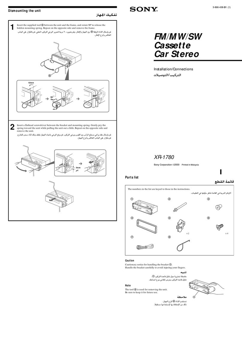
Table of contents
Other Sony Car Receiver manuals

Sony
Sony CDX-C90R User manual

Sony
Sony XR-C7500RX User manual

Sony
Sony MEX-DV1600U Product guide

Sony
Sony CDX-GT40UW User manual

Sony
Sony XS-GTR100L User manual

Sony
Sony ST-SE370 - Tuner User guide

Sony
Sony CDX-F7710 Operating Instructions (English Product guide

Sony
Sony CDX- gt929u

Sony
Sony CXS-GT5616F User manual

Sony
Sony XR-C102 User manual

Sony
Sony XR-CA800 Product guide

Sony
Sony XR-CA660X User manual

Sony
Sony MEX-N4200BT User manual

Sony
Sony CDX-4480ESP - Am/fm Compact Disc Changer User manual

Sony
Sony CDX-C410 Product guide

Sony
Sony XR-CA624X Product guide

Sony
Sony CDX-L570X Product guide

Sony
Sony CDX-A250 User manual

Sony
Sony CDX-CA710X Addendum to User manual

Sony
Sony CDX-CA730X User manual