SONY XR-C110 (E,S,C) 3-856-406-31 (1)
SONY XR-C210 (E,S,C) 3-800-373-71 (1)
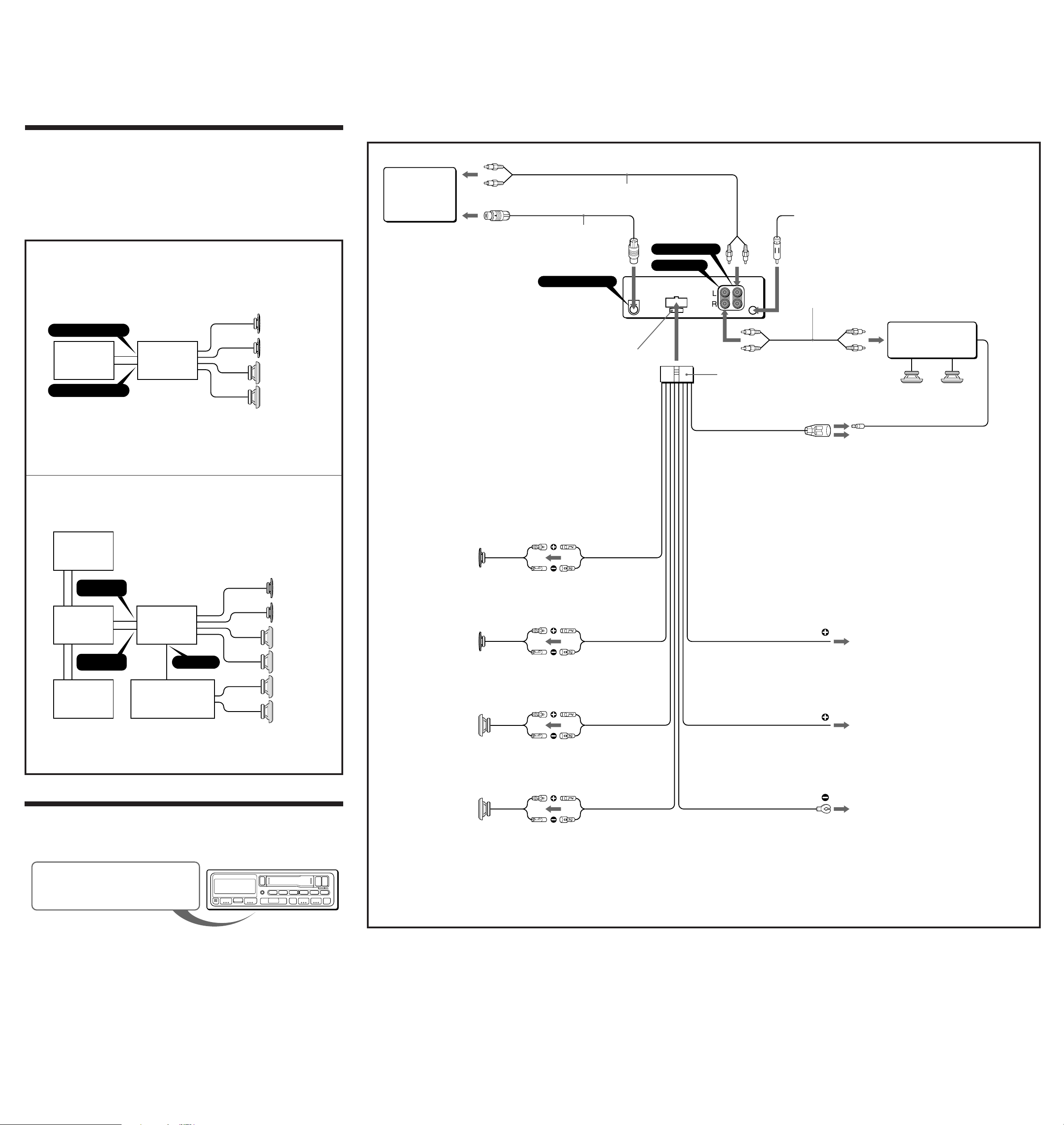
Connection Diagram
Example 1
BUS AUDIO IN
BUS CONTROL IN
For connecting two changers, the source selector XA-C30 (optional) and the BUS cable RC-61 (1 m) or RC-62 (2 m)
(optional) are necessary.
XR-C117
LINE OUT
BUS
AUDIO IN
BUS
CONTROL IN
Frequency Select Switch
The AM (FM) tuning interval is factory-set to the 9K (50K) position. If the frequency allocation system of
your country is based on 10 kHz (200 kHz) interval, set the switch on the bottom of the unit to the 10K
(200K) position before making connections.
Front speakers
Rear speakers
Front speakers
Rear speakers
Rear speakers
Example 2
Caution
•This unit is designed for negative ground 12 V DC operation only.
•Before making connections, disconnect the ground terminal of the car battery to avoid short circuits.
•Connect the yellow and red power input leads only after all other leads have been connected.
•Be sure to connect the red power input lead to the positive 12 V power terminal which is energized
when the ignition key is in the accessory position.
•Run all earth wires to a common earth point.
Connections
Connections Example
Rear speakers
BUS AUDIO IN
LINE OUT
BUS CONTROL IN
from a car antenna
Fuse (10A)
5
to a power antenna relay control box
AMP/ANT REM
Max. supply current 0.3 A
Blue/white striped
Left
Front speakers
Right
Left
Right
to the +12 V power terminal which is energized in the
accessory position of the ignition key switch
Be sure to connect the black earth lead to it first.
to the +12 V power terminal which is energized at all times
Be sure to connect the black earth lead first.
to a metal point of the car
First connect the black earth lead, then connect the yellow
and red power input leads.
CD changer
RCA pin cord (RC-63 (1 m), RC-64 (2 m) or RC-65 (5 m)) (not supplied)
Power amplifier
Rear speakers
Red
Yellow
Black
BUS cable (supplied to CD changer)
RCA pin cord (supplied to CD changer)
Change the position with a jeweler’s screwdriver, etc.
White
White/Black striped
Gray
Gray/Black striped
Green
Green/Black striped
Violet
Violet/Black striped
XR-C117
CD changer
CD changer
Source selector
CD changer Power amplifier
Notes on the control leads
•The power antenna control lead (blue/white striped) supplies +12 V DC when you turn on the unit.
•A power antenna without relay box cannot be used with this unit.
Memory hold connection
When the yellow power input lead is connected, power will always be supplied to the memory circuit even when the ignition key is
turned off.
Notes on speaker connection
•Before connecting the speakers, turn the unit off.
•Use speakers with an impedance of 4 to 8 ohms, and with adequate power handling capacities. Otherwise, the speakers may be
damaged.
•Do not connect the terminals of the speaker system to the car chassis, and do not connect the terminals of the right speaker with
those of the left speaker.
•Do not attempt to connect the speakers in parallel.
•Do not connect any active speakers (with built-in amplifiers) to the speaker terminals of the unit. Doing so may damage the
active speakers. Therefore, be sure to connect passive speakers to these terminals.


