manuals.online logo
Brands
  1. Home
  2. •
  3. Brands
  4. •
  5. Sony
  6. •
  7. Cassette Player
  8. •
  9. Sony MEGA BASS CFD-073 User manual

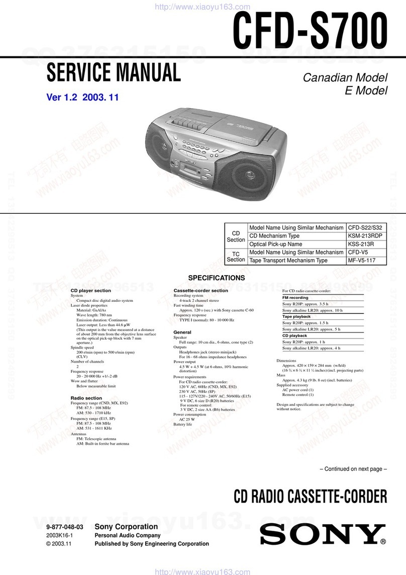
Sony MEGA BASS CFD-073 User manual

SERI|ICE
MANUAT US Model
Canadian
Model
AEP Model
UK Model
E Model
MreABl$S
SPECIFICATIONS
AUDIO
POWER
SPECIFICATIONS
Full-range
speakers:
With
3-ohm
loads,both
channels
driven
from
200-10,000
Hz:
rated
3.5Wper
channel
mini-
mum
RMS
power,
with
nomorethan
100/ototal
harmonic
distortion
in
ACoperation.
Super
woofer:
With4-ohm
loads,
driven
from50-250 Hz:rat-
ed
8W minimum
RMS
Power,
with
nomore
than
100/ototal
harmonic
distortion
inAC
operation.
OTHER
SPECIFICAÏIONS
Tape
recorder
section andgeneral
Recording
system 4-trâck
z'channel
stereo
Fast
winding
time Approx.
2min.
withSony
cassette
CbO
Frequency
response 60- 10,000
Hz
Full-range
speakers:
10cmdia.,
Super
woolel:
8cmdia.
Full-range
speakers:
4W+
4W(at
3ôhms'
100/0
harmonicdistortion) '
Super
woofer:9 W(ai4ohms.
100Hz,'
10o/oharmonic
distodion)
Inputs Mixing
microphone
input
jack
(miniiack)
SensitivitY
2.5
mV
For
low
imPedance
microphone
Two
line
inPut
iacks
(Phono
iacks)
Sensitivity044V ':
Input
impedance
47kilohms
orhiOhâr
- Continued
onnext
Page
-
CD
RADIO
CASSETTE.GORDER
Radioseclion
Frequency
range
Antennas
Speaker
Power
oulput
FM:Telescopic
anlennâ
AM:
Built-in
ferritebar
antenna
CO
playersection
System
Laserdiode
Properlles
Spindle
speed
Error
correclron
Number
ofchannels
Frequency
resPonse
Wow
andflutter
Compacl
discdigilal
audiosystem
iilaterial:
GaAlAs
Wavelength
780
nm
Emission
durâtion:
Continuous
Laser
output:
Lessthan
44.6
tW'
' Thisoutput
isthe
valuemeasured
aladis-
tanceofaboul
200
mmfromlheobjective
lenssurface
on
theoplical
pick-up
block.
200
(p.m.
lo500
r.p.m.
(CLV)
Sony
Super
Strategy
Cross
lnlerleave
Read
Solomon
Code
Two
20-2O,OOO
Hz
:9'
dB
Below
masurable
limit
Model
NameUsing
Similar
Mechanism
CDSection CFD-D75
cFs.Dsfl)
cFs-D960
TapeSection
Optical
Device
Name KSM.lsOBGN
Tape
Transport
MechanismTyPe MF.D7962
FM AM
AEP,UK model 87.6
- 107MHz 531
- 1602kHz
US,Canadian,
E model 87.6
- 108
MHz 530
- 1605
kHz
SOI\TY
Outpuls
Power
requirements
Batterylife
Dimensions
Weight
Headphones
jack
(slereo
minijack)
For16-68 ohmsimpedanceheadphones
Two
CDoutput
jacks
(phono
iack)
Load
impedance
10kilohmsorhigher
Rated
output
1.1Vrmsatload
impêdance
47kilohms
12VOC,
eightR20
(size
O)
batreriesfor
CO
radiocasselte-corder
ThreeRG
(sizeAA) batteriesfortimer€tock
Batteries
forCDradio
casselte-corder
6N x 1725
x 198.5mm(w/h/d)
(24r/sx 6trt
x 7%inches)
incl.
projecting
parts
andcontrols
Approx.Z2 k9,incl.
batteries
TABLE OF CONTENTS
Section
Specifications
Title Page
Features
1. SERVICING
NOTES
Safety Check-out
Not€son Handling
the OpticalPick-up
Block or BaseUnit
ChuckPlate
Jigon Repairing
)
6
6
I
2
2.
(Approx.
15lb 14
oz)
Supplied
accessory AC
powercord(1)
Oesignandspecifications
subjecttochangewithoutnotice.
CFD-D73isanFM/AM
compact
disc
cassette-corder.
High technical device
Theauto-reverse
functionwhich
enables
torecord
without
turning
overthe
cassetle.
High quality sound
Powerful
bassisproduced
with
theSony
MEGA
BASS
system.
Thisunitincorporates
asup€r
woofeiwhich
hasits
o!,/namplifi-
erseparatefrom
theonefor
thefull-range
speaker
High performance, high lidelity CD player with many
tunctions
. Repeat
functionfor
playing
either
theentire
disc
oradesired
selection.
. Program
play
for
playing
selections
inthe
desired
order.
. Shuffle
play
torplaying
seleclions
repeatedly
i! random
order
Oigital
clock timer
Waks
uptoaradio,
taped
orCD
program
orrecord
radio
program
atlhepresel
time.
GENERAL
Location andFunction of Controls
Settingthe
Clock
Disc Playing
3. DISASSEMBLY
4. ADJUSTMÊNTS
4-1. Mechanism
Adjustment
4-2, Electrical
Àdljustments
5.
)-l.
5-2.
f,-J.
5-4.
Tape
Recorder
Section .
RadioSection
CDSection
DIAGRAMS
Circuit BoardsLocation
RadioSectionPrintedWfuing
Boards . . . .
Radio
Section
SchematicDiagram
. . . . . .
TapeRecorder
and
AudioSection
Printed
Wiring
Boards
. ......23
5-5. TapeRecorder
aûd
AudioSection
SchematicDiagram .... -.... 27
5-6. CDsectionschematicDiagram
........ 3l
5-7. CDSectionPrinted
Wiring
Boards
..... . 35
6. EXPLODEDVTEWS. .......39
7. ELECTRICAL
PARTS
LIST
.... .. .. . 47
SAFETY.RELATED
COMPONENT
WARNING!
!
coMFoNENTS
tDENItFtED
By MARK
I on oorreo
L|NEW|TH
MARK
a ONTHE
SCHEMATTC
DTAGRAMS
ANO IN THE PARIS LIST
ARECRITTCAL
TOSAFE
OPERATION.
REPLACE
THESE
COMPONENTS
WITH
SONYPARTS
WHOSE
PABT NUMBERS
APPEAR
AS
SHOWN IN THIS MANUAL OR IN SUPPLEMENTS PUB.
LISHED BY SONY.
ATTENTION AU COMPOSANT AYANT RAPPORT
À r_r
sÉcunrrÉ
r
LES
COMpOsaNrs
tDENTtFtÉs
pAR
UNE
MAROUE
A
SURLES
DIAGRAMMES
SCHÉMATIOUES
ET
LA LISiE
DEs ptÈcÊs
soNT cRtrteuÈs pouR r_a
sÉcuniÈ
OE FONCTIONNEMENT.
NE REMPLACEB
CESCOM.
POSANTS
OUE PAR DESPIÈCES
SONY
DONT
LES
NUMÉRos
soNT DoNNÉsDANScE MANUEL
oU
DANS
LES
SUPPLÉMENTS
PUBLIÉS
PAR
SONY.
8
l0
1t
It
l2
14
l8
19
20
US,Canadian
model 120
VAC.60Hz
AEPmodel 220V AC.50 Hz
UK
model 240VAC.50Hz
E model 1
10.120V.22Oor 24OVAC
adiustable,50/60Hz
Power
Comnsumption
AEPmodel 25W
US,UKmodel 27W
E model 20W
Canadian model 37W
FMRecording Playback
Sony
SUM-1
(NS) approx.
2H approx.
5H
SonyAlkalineAM1
(N) approx.35H approx.
9H
-2-
sEcTloN
1
SERVICING
NOTES
oSAFETY
CHECK.OUT
After correcting the original service problem,
perfolm the following safety check before releasing
the setto the customer:
Check the antennâ terminals, metal trim, "metallized"
knobs, screws,and all other exposedmetal parts for
AC leakage. Check leakageasdescribed below'
LEAKAGE TEST
The AC leakage
from any exposedmetal part to
earth ground and from all exposed
metal parts to any
exposed metal part having a return to chassis,
must
not exceed 0.5
mA (500 rnicroampers). Leakage
current can be measured by any one of three
methods.
l. A commercial leakage tester, such as the
Simpson 229 or RCA WT-540A. Follow the
manufacturers' instructions to use theseinstru-
ments.
2- A ba
ttery-operated AC milliammeter. The Data
Precision 245 digital multimeter is suitable for
this
job.
3. Measuring
the voltage drop acrossa resistorby
means of a VOM or battery-operated AC volt-
meter. The "limit" indication is 0.75
V, so
analog meters must have an accurate low-
voltage scale. The Simpson 250 and Sanwa
SH-63Trd are examplesof a passive
VOM that
is suitâble. Nearly all battery operated digital
multimeters that have a 2V AC range are
suitable. (See
Fig.A)
To Exposed Metal
Parts on Set
O.r
5
pF
Fig.A. Using
anAC voltmeter to checkAC leakage'
o
US model
: AC:
Canadian model:
AEP model
: AC:
UK model
: AC:
E model
: AC:
12OY6QHz27W
AC: 120V
60Hz
37W
22OY-5OHz 25W
240V-5OHz 27W
11O,/12O,/
22O,/24OV
-5O,r 6OHz20w
CAUTION
Use
of controls
or adjustments
or performance
of proceduresother than those
specified
herein
mav result
in hazardous
radiation
exposure'
Model ldentlflcatlon
MODEL
NO. CFD-D73
CD RADIO
CASSETTE-CORDER
DC: 12V FLASHLIGHT
BATTERY
SIZE
D R2O
X8 OR EOUIVALENT
DC
: 4.5V FLASHLIGHT
BATTERY
(COMPUTER,,,CLOCK)
SIZE
AA R6 X3 OR EOUIVALENT
SECTION
NOTES
ON HANDLINGTHE OPTICAL
PICK.
UP BLOCKOR BASE UNIT
The laser diode in the optical pick-up block may
suffer electrostatic breakdown because
of the poten_
tial difference generatedby the charged
electrostatic
load, etc. on clothing and the human body.
During repair, pay attention to electrostatic break-
down and also use the procedure in the printed
matter which is included in the repair parts.
The flexible board is easily damaged and should be
handled with care.
NOTES ON LASER DIODE EMISSION CHÊCK
The laser beam on this model is concentrated so
as to be focused on the disc reflective surface
by the
objective lens in the optical pick-up block. There_
fore, when checking the laser
diode emission,
observe
more
than25 cm awayfrom theobjective
lens.
LASER DIODE AND FOCUS SEARCH
OPERATION CHECK
l. Turn POWER switch on with no disc
inseted and
make Function switch to CD position.
2. Openthe lid for CD.
3. Turn on 5702 asfollowing figure.
4. Pre.ss
) key.
5. Confirm the laser diode emission while observing
the objecting lens. When there is no emission,
Auto Power Control circuit or Optical pick-up is
broken.
Objective lens movesup and down threetimes for
the focus search.
CHUCKPLATE
JIG ON REPAIRING
On repairingCD section, playing a discwithout the
CDlid, use
ChuckPlate
Jig.
. Codenumber
ofChuckPlate
Jig:
X4918-255-l
NOTE ON REPAIRING
The spindle
motor (M702) andthe tumtable
assem_
bly are
individually supplied
asrepairpads.
When repairingM702, please
order the turntable
assembly
together.
Dimension
isasfollows.
turntable assemblv
19.4t0.Inm
spindlemotor (M702)
Turn oô S7O2with
€ slender
screwdrive..
-4-
-€
Ë * iËeg
n Ëa Ë ËsËËË
gssi;galËËËËgËâË,gsgF
Re
E€€
âËï
eHE
g Ë CH E
ë. ; É= Ë
*Ëââ;
s : " uÉ
! s Ë Ë!t Ë
E EiË.t *Ë
ËÈç t
EsËigË$eeeiiËgËs*H
Ë= Ë , e*
gÊ
si ! H EËrËË
ËsËËet;gËgEE
È ËËgË
ËËË: rgss^e
Ë
i
ËlËËiË,ËË
ËË
ËË
g
ËËË
ËiË,Ë
ëEE EE]E EE E E
sEcTtoN2
GENERAL
@BE@EBtE] BE] ts
@86
E]
tr EE} r.1JEJ t!.1 t-!l tll tlj
-5-
l-fl Fe,
Ii1-EE*
| .T-l
'o
iÊ
'î;
rE
'ô5
II
;g
EË
9t+
sô
EI
ts.fl
ËË
s!E
-dul
I
*
E
.:ï
d.-
EI;TI
rlÈtl
.g I crl
3| -il
t I cll
rl ll
ELAJ
i
ËHo
1s
ÉiËËË
Ël*Ë,!F
-;:-r E
l..-l--E
lrnl fl.E
t-tl
l^ll
I ut :E
#Ë
Ël;,Ëg
3Ë3Ë
tr.oÊ Ëse,iËËe
6
r
.9
g
i i9
à i=
RË E 9 ?
;t 6 5 :
Êa È |l È
Eg 6 5 ,
,lË r c c.r
:
o
o
o
E
I
*
f
2
E*
-ëo
* sd
ir$ g
ËÊ.ËE
(aç
Ëq
E .tç
Ë ËËË
B- ; gË
ËI ËE*
:È É
tE e$
IÉËI
O ë , i.
EË Ërl
EË
ggË
ËËrEi
E€EË€
sÉ!gË
: ; EgsË
Ë,Ë!Ë;FF
ËsgË,Ë
ËiiËgËËiË
lrlt
IâII Ë
tstiÈ
El
3sËs
ts
EE
lE
4Ë
SE
ÈT
BA
=E
.Ê
E
ET
È;
ti
*É
!
.l|
z
^ rnm
i illll;lFllr
.i, ml[:1ll
E ! ,
lùlt
,
z 8 [-1, L-J
=_s
tÈ.
lX
86
ûd rll
Ët lllEt
Ë: tu
EË
;
*
I
r--::--! x
lçlËÊ
I ru
| Ëi
|--
|Ëçr
| |
ris
l^ llFÉ
tË të[g
' '!àÈ
iËt
É;;
{ ôl
s€
çÈ
ë€
.5È
t=E
Èl
E:
<Ë
iâo
:t
6
ù
à
E
III
!
.r
E
a
I
I
E
à
Ë
i
!
!Ë
E
É
-6-
-L*
O
o
pJEoq
o!pBr
lo
-8-
zl xgA8+
ôurdder
lD
ouvo8otovuoNvstssvHc
u3NnI
lâu!q93 J9ddn
o
z1
x
e^€+
6ulddet
O
s3t'lsl,rSssv
r3Ntsv9 uvld oNv lNouJ
'us^!6
ropJo
leJlraurnu
3ql u! êrnparord ^lqurassgslpaql |\^ollol :9loN
^lgl |3SSVStO
e
Norrcrs
'6 âABdâaS
0Nt:)Ntuls
ouoc 'tvlo
^lqlu9ss8
tautqec rsa.l
o
plt^Jatleq
l)
s!8seqc
raun!
09
x eg+'6u!ddBr
pue
('srd
Z)Z
1
x 0Ag+'ôuldder
G)
\
olpeJ
eqluo
tdNc ruorl
peal
euuslueaql
lno llndo
1/iih\
-t((
DIAL CORD
STRINGING
1. Preparation
tension
5O0
s
2. Dial
Cord
Stringing
3. DialPointer
Setting
l) Suspend
rhe
fixingptate
to spring.
,
-k5\.
s
\
t@ 3 tu.n
@ Suspendthe dial cord
to t porlion.
+[+
@ Setas
above.
-9-
KS ---{ly)
_'<iill
O Turn
the
tuningknob
fully In the direction of arrow.
---1--
CFD-D73 |SECTION
4
pinchrollers
rubberbelts
idlers
4.1. MECHANICAL
ADJUSTMENT
TAPE RECORDER
SECTION
PRECAUTION
I. Clean the following Palts with a
âlcohol-moistened
swâb:
denatured-
record/plaYback
head
erase
head
capstans
2. Demagnetize
the record/playback/erase
headwith
a
head
demagnetizer.
3. Do not use â magnetized
screwdriver
for the
adjustments.
4. After the adjustments,
applysuitable
locking com-
pound
to theParts
adjusted.
5. The adjustments
should beperformedin the order
eiven
in thisservice
manual.
ADJUSTMENTS
Head
HeightAdiusltnent
Adjustmcnt Procedure:
1. Insert
a
mirrorcassette
CQ-009C.
2. Maketheset
to FWD
playbackmode.
3. Loosen the FWD tape guide fixing screw and
adjust with inserting the adjustingshim to eumi-
nate tape curl and tape twist i'l the portions of
tape
guide
and
head.
4. Make
theset
to REVplayback
mode.
5. Loosen the REV tape guide fixing screw aûd
adjust with inserting the adjustingshim to elimi-
nate tape curl and tap€ twist in the portions of
tape
guide
and
head.
6. After adjustmeflt, apply suitable locking com-
poundto the fixing screws.
Adjwtment Locstion:
Torque
Measurcment
Mod. lorgua matar Malrr rcrding
FWD cQ-102C
221o
55
g'cm
(0.30to 0.76oz'inch)
FWD
back
tension 3.0to 5.0
g.crn
(0.04to 0.06oz'inch)
REV cQ-l02Rc
25to 55
g'cm
(0.34to 0.?6oz'inch)
REV
backtension 2.5
to 5.0
g'cm
(0.04to 0.06oz'inch)
FF cq20l D80
to 135
g'cm
(1.10
to 1.84
oz'inch)
REW cQ-201B 80
to 135
g'cm
(1.10
to 1.84
oz'inch)
TapeTcnsion
Modo Tln3ion mltar Mctcr r!sding
FWD cQ403A morethân
110
g
(more
than3.88oz)
REV cR-403R
haêd haight âdiusting
shin (R)
Plrt No. 1
3-344-7
66-01 0.1
3-344-766-110.2
3.344-1
66-3t 0.3
Prrt No. i
3-144-7
65-01 0.1
3-344-765-rr 0.2
3.344-765-21 0.3
-10-
CFD.D73
4-2. ELECTRICAL ADJUSTMENTS
TAPE RECORDER
SECTION
PRECAUTION
l. Adjustments should be performed in the order
given.
Generally playback circuit adjustmentsshould be
completed before performing recording circuit
adjustments.
2. Adjustments shouid be performed for both L ch
and R-ch.
Switches and controls should be set as follows
unless
otherwisesPecified.
. Positions
of switches
and control knobs
FUNCTION ....... TAPE
ISS ... .....2
MODE . ..... ?
GRAPHIC EQUALIZER. . . . mechanicalcenter
voLUME . . MIN
OdB- 0.775V
Tape
Speed
Adiustment
AdjustmentProccdure:
- FWDplayback state
-
'€stûpe
ws48A
(3kHz.OdBl
speadchecker
of
ftequency counter
PHONES
AdJustment
Valuc: normalsPeed
Spsod
Chcckrr Frôquancy countel
-0.83V' 2.975
to3,000
Hz
The frequency differencefor REV sideshould
bewithin 1.37o
(40 Hz').
Adjustment
Locatlon: RV60l
Adjust the semi-fixed variable resistor
built in the motor.
(Adjust with inserting lhe screwdriver. Tuning
clockwise makes the speed high.)
. Standard
input level
lneut
Pin MrxMtc LINÊ IN
Signal source impedance 300{r l0
kn
Input signallevel 2.5
mV
(-s0 dB) 0.436
V
(-5 dB)
Frequency I kKz I kHz
a Standardoutput level
Ontput Pin SP OUT (L.RI PHONES
Signal
source
impedance 4fi 32
ç7
Output signallevel 0.775
V
(0dB) 0.245
V
(-10
dB)
Head
Azimuth
Adjustment
AdjustmentProcedure:
l. FWD
playback
mode
test tape
P-4.4a63
(6.3 kHz, -lO dB) oscilloscope
Turn the scrcwand confirm the output peak
point. Whsn L-CI{ end R-CH peaks do not
match,
adjustthescrew
to the pointwhere
the
within
2dB within
2dB
L.CH
pcak R.CH
peak .---r Ecrew angte
Oscillo:copr rcsurgc wovef
orm
@@@so
in phaEe f 9d
OK .r3f - r
80"
NG
3. Changeto REV mode andrepeatstepsI aûd 2.
Adiustment Locetion:
PHONES
RADIO SECTION
FUNCTION
switch:
RADIO
tAMl
BANDSELECT
switch:
AM
3æ6anplitude modr lation
by 4(M Hz signal
ou@utlevel:
as
low aspossible
tFMl
BAND
SELECTswitch:FM
F,lt
aFssc
225 kHz frequency deviation
by 4(n Hz signal
ou@utlevel:
aslow aspossible
. Rcpcâl thc procedure3 in cach sdjustmcnt
several
timcs, and thc frcqucncy coveragc
and
trackingrdjustmentsshouldbc finally doncby
thètrimmcr capacitors.
AiT' FF SSG
PHONES
AM FREQUENCY
COVERAGE
ADJUSTMENT
Adjustforamaximum
readingonVTVM.
TI 520kHz
cTl-4 I,6E0kHz
AM TRACKING AÀ'USTMENT
Adjust
fora
maximum
readingonVTVM.
I.J 62A
kHz
CTI-3 1,400
KHz
FM FREQUENCY
COVERAGE
ADJUSTMENT
Adjustforamaximum
reading
on
VTVM.
L2 US,
Canadian.E: 86.5MHz
AEP,
UK: E7.0
MHz
West
Germany: 87.35
MHz
cTt-2 US,Canadian,
E: 109.5
MHz
AEP,
UK: 108.3
MHz
West
Germany: 107.8
MHz
FM TRACKING
AOJUSTMENT
Adjust
foramaximum
reading
onVTVM.
LI US,Canadian,
E: 86.5
MHz
AEP,
UK; 87.0
MHz
West
Germany: 87.35
MHz
cTl-I US,Canadian,
E: 109.5MHz
AEP,
UK: 108.3
MHz
West
Germany: 107.8
MHz
-12-
[FM VCO ADJUSTMENT]
Procodut€:
FM NF SSG
0.0O1
pF Mpin@
Carrior Froqusncy: According to the colot of the mâlk on
cemmic frlter (CF2).
Output Lsvolr80 - 90 dB
f) Adjust with RVI so that the reading
on the frequency
counter
becomes76.0
10.5
kHz.
IAdlustmentsLocation]
RVl
FMSTÊREO
VCOAdiusûnont
lRadio Boardl
AM Tracking
Adiunmmt
cT1-1
cN3
(ANT IN)
FM
Frequoncy
Covorago
Adiustm€nt {crr-2
tL2-
LI
FMTrscking
Adiunment
Mark Crrrier Frequancy
red 10.7 MHz
blue 10.67
MHz
orange 10.73
MHz
bl,ack 10.64
MHz
white 10.76
MHz
lRadio Boardl
FpsecrroNl
Noter
onAdiustmont
l. Perform
adjustmentin service
mode.
After adjustment,be sure to release
service
mode.
2. Performadjustmentsin theorder
given.
3. Use
the
disc
(YEDS-t8,
Part
No.3-702-l0l-01)
onlywhensoindicated.
EeforeAdjustment
Put the set into senice mode and perform the
following
checks.
Repairif there
are
any
problcms.
. SledMotorChsck
l. Press
>-+ I keys.
2. Press)N,l(keys and confirm that the FOp
moves
smoothlyfrom the innermost
to outer_
most circumference
and bâck smoothly and
withnocatching
orabnormal
noises.
>>l : FOP
moves
to theouter
circumference
K< : FOPmoves
to the
innercircumference
. Focu3
Search
Check
l. Press
) key. (Focus
search
operation
is per-
formed
continuously.)
2. Look at the FOP objective
lensand confirm
that it movesup anddown smoothly,
with no
catching
orabnormalnoises.
3. Press'l key.
.Confirm
that focussearch
operation
stops.
If it
doesnot,pressI keyagainlonger.
Howto Put
theSetintoServiceMode
1. Short-circuit
following
pcirtions
onthe
CDcontrol
board.
2. Turnthe
POWER
on.
VCO Adjustment
Adjustment Procedure:
l. Short-circuit @ portion on CD main board.
2. Adjust with RV703 so that the reading on
frequency
counter
becomes
4.3218
MHz.
3. Release
the short-cûcuit @ portion.
Adjustment Location: ICD
MainBoardl
frequency counter
-14-
E-F
Balance
Adiustment
Thisadjustmentisto be
done
when
the
optical
block
is
replaciid.
Adjusamenl
Procedure:
oscilloscope
(OC range)
COnF boord
rE(tc7ot @ )
/REF
ttcTot
@ t
l. Connectthe oscilloscope
betweenIC70l pins
(20) and (L!).
2. Puttheset
intoservice
mode.
3. Pressthe>N and
f( keys
to movetheFOPto
the center.
4. Insertdisc
(YEDS-I8)
and
press
) key.
5. AdjustRV70l sothat the oscilloscope
traverse
waveform
issymmctrical,
osshown
in thefigtrre
below.
6. Release
service
modeafter adjustmentis com-
pleted.
A. B
FocusBiasAdiurtment
This adjustment
is to be
blockisreplaced.
Âdjustmcnl
Proccdure:
done when the optic l
oscilloscopo I
DCrangc
I
CD AF boed
RFO
(tc7or@)
\REF
(tc7ot @t
Connect the oscilloscope between IC70l pins
@"na
@.
Put the setinto service
mode.
Pressthe )) and 111 keys to move the FOP to
the center. (Move the FOP to the music area
on the disc to enable easy visibility of the eye
Pattern.)
Insert disc
(YEDS-I8) and press ) key.
Adjust RV702 so that the oscilloscopewave-
form is as shown in the figure below (eye pat-
ternt.
A good eye pattern meâns that the diamond
shape
(O) in the center of the waveform can be
l.
2.
3.
5.
clearly distinguished.
6. Release service mode after adjustment is com
pleted.
a RF signal
reference
waveform (eye pattern)
VOLT/OIV
: O.2V
TIMÊ/OlV
: 500ns
VOLT/DIV: ,v
TIME/DlV: tmt
When observing the eye
scope for AC range and pattern, set the oscillo-
raise vertical sensitivity.
AdjustmentLocation:
ICD RF BOARD]
- Printed Sid€ -
Ê.ÈB.hnc. Adiwtmont, o.clllorcope
(@ ridel
RV7ol: E-FBalsnca
Adlu3tm.nt vREFr E-FBllanco
Adludmom, qcillorcope (JC ridel
Focus
Bi8 Adiutment otcillo.cop. (et rid.l
RV7O2|
FocurBia Adiu3tm.nt
CFD.D73
-1 5-
CFD-D73
FocusÆracking
GrinAdiustment
A frequency response
analyzet
is necessary
in
order
to perforrn
this
adjustment
exactly.
However,thisgainhas
a margin,so even
if it is
slightlyoff, thereis no problem. Therefore.do not
perform
this
adjustment.
Focus/trackinggain
determines
the
pick-up
follow-
up (vertical
and horizontal)
relative
to mcchanical
noise
and mechanical
shock
whenthe 2-axis
device
operat
e,
However,
as
these
reciprocate,
the
adjustment
isat
thepointwhere
both
arc
satisfied.
. lvhen gain is raised,
the noise.when
the 2-axis
devic€
operates
increascs.
a Whengain is lowered,
it is more susceptible
to
mechanical
shock
and
skipping
occurs
moreeasily.
. When
gain
adjustment
isoff, the
symptoms
below
zPpeal
.
The following isa simpleadjustmentmethod.
- Simple
Adjustment
-
Not.: Since
exactadjustment
cannot
beperformed,
remem-
berthepositions
of the
conrrols
before
peiforming
the
a justment. If the positions
afterthe
simpleadju3t-
mentareody a littledifferent,
return
the
controls
lo
the
oridnal
position. oscilloæope
(DC rangte)
CD main board
VBEF
Keep
theset
horizontal.
/If the set is not horizontal,
thisadjustmentl
I cannot
beperformed
due
to the
gravity
against
I
\the
2axisdevice. I
Insertdisc
(YEDS-I
8)and
press
) pLAy button.,
Connect.oscilloscope
to main
amp
board
FE.
Adjustment RV705 so that the waveform is as
shown
in the figurebelow.(focus
gain
adjustment)
o
l.
)
J.
4.
voLT/Dtv:
TIME/DIV:
l@mV
0v
Incorrent
Examples
(DC
onadjusted
waveform) level changes
morethan
high focus gain
VOLT/DIV:
TIT'E/DIV:
25O
mV
VOLT/DIV:
TIME/DIV:
lO0
mV
75
mV
OV
Grin
Symplomr Foqlt Tr.ckirrg
. Thc
time
untilmusicstarts
becomcs
longcr
for STOP
rf) PLAY or automatic
selecrion
(1a.1
)}lbuttons
Prcsscd.
(Normâlly
takca
about
2scconds.)
low lowor high
. Musicdoe3
notstartand
dilc conlinuca
to rotatc
for STOPr)) PLAY or
automâtic
selection
(
|<<
})l buttonspressed.)
low
. Sound
isintcrrupteddur-
int PLAY. Ortimccount-
erdispley3tops
progrest-
int.
low
. More
poisc
during2-exir
dcviccopcration. hith high low focus gein
-1 6-
).
6.Comect
oscilloscope
to main
boardTE.
Adjust RV704 sothat the waveformisasshown
in
thefigurebelow.(tracking
sainadiustment) VOLT/DIV:
1V
T\ME/D|V: 2mS
a Incorrect
Examples
(fundamental
waveappears)
VOLT/D|V: I V
TIME/O|V: 2 ms
VOLT/DIV:
1V
TIME/DIV: 2 mS O [cD Main
Bosrdl
00mv
mS
AdjustmentLocation: CDMainBoard
't
OOmV
mS
TE
FEI
,oo VREF
' when e frequencY
rcsponse
analYzer
is usecL
mS
n
a RV7O5
(focus gain adjustmentl @ RVTU
(tracking gain adiustnent)
low tracking gain
high track ing gain
lhiglier fundamental wave than lor low gain)
-17-
SECTION5
DIAGRAMS
5-1, CIRCUIT
BOARDSLOCATION
leaf svvitchboard
POWer
board
headphoôe
board
graphic
equalizer
board
lC BlockDiagram - Radio
Section
-
tcl cxAl2385
OPENswitch board
CD switch board
radio LED board
CD main board
3
(V)
SÊLboard
(E
model)
CD cootrol board
-18-
5.2. RADIO SECTION
PRINTED
WIRING BOARDS
123456
AANT
I
FM
TELESCOPIC
AI,{TEN
NA
BLK OTHER
- - _ - - t--,------------
- ii'
I nl Jus,caraDra
â'hl-T:-
IRADIOBOARDI
ta t irHil
?ttr!;
CNJ2
<Fl?
II
X-
ôlT0'-
I MA|N
80aR0
| (See
page
241
I
lo-r,.r,
l--ll
ciîb
cF1
B
c
D
E
@:us,
@:lee,ux,
e
. Semlconductor
Locatlon
)
Noteon Printed
Wiring
Boardsi
. o- : parts
extracted
from
the
componeôl
Side.
. ;- : parts
extracted
from theconducto.side,
Note on Schamltic Diag.am:
and tantalums.
. lll ""O""norr
are
in!F untess
olnerwise
noted.
50WV or less
are not indicâteo
except fo. ele
. All resistors
are in .ç!
and %W or less
unless
specified.
. -: B+ Line
o l-] j adjustmentfor repair.
Ref.
No. I Locarion
c8
c€
D1
D2
u5
o4
04
o5
tcl
o1
o2
E_2
o_2
È8
E4
(RADIO
BOARD)
B7
/ RADto
LED
\
\ BOARDI I
E4 l
I
D3 l
-19-
5.3. RADIO SECTION
SCHEMATICDIAGRAM
3
12
--l
tasstsI
-J
OTHER
(Ssepsg€
23)
TO
MAIN
BOARO
1I
I
r)
r _l
YHt AEP,
<a>1 MOD|
<B-
<cx
<Dà (See
pa
iFA€,^l,l
;-;-
\LEDBOAR
l-cnÏ
22P
(US.CANAOIÂN,
E
MODEL
)
2?P
IAEP,
U( MODEL
)24P
27P
US,CANADIAN
MODEL
L- - - .
AEP,
UK,
EJ L- - ----J
Voltage and waveforms are dc wlth respect 1o ground
under nollgnal (detuned) conditrons'
no
mark
:FM
( ):
AM
Voltages are laken wrth a
Voltaqe var
lal
lo
ns mav
tion to
lera
nces
Signal
Palh
+ :FM
o Semiconductor
LeadLayouts
cxAl1820.2
Wy
MODEL
8A629OA
(r---.---\|
LL. ,.J
t\_--------Jl
TIIIIfiITITÏ"
cxA1081M
!o rô
Ill|lll|mrq
tl
tl
ffi
BA3!112L cx
pPl
c
aê
t
cxAt238S I
voM (50
kr)
/v
).
be noted due lo normal Produc-
cN3
[
RAOTO
B6ARD)
-20-

Other Sony Cassette Player manuals

Sony WM-EX190 - Walkman Cassette Player User manual

Sony

Sony WM-EX190 - Walkman Cassette Player User manual

Sony CFD-560 User manual

Sony

Sony CFD-560 User manual

Sony TC-WE425 - Dual Auto Reverse Cassette User manual

Sony

Sony TC-WE425 - Dual Auto Reverse Cassette User manual

Sony Walkman WM-FX161 User manual

Sony

Sony Walkman WM-FX161 User manual

Sony Walkman WM-GX788 User manual

Sony

Sony Walkman WM-GX788 User manual

Sony CFM-20 User manual

Sony

Sony CFM-20 User manual

Sony CFS-W338S User manual

Sony

Sony CFS-W338S User manual

Sony TC-S3 User manual

Sony

Sony TC-S3 User manual

Sony WM-EX190 - Walkman Cassette Player User manual

Sony

Sony WM-EX190 - Walkman Cassette Player User manual

Sony WM-GX410 - Walkman User manual

Sony

Sony WM-GX410 - Walkman User manual

Sony Pressman TCM-5000EV User manual

Sony

Sony Pressman TCM-5000EV User manual

Sony Walkman WM-EX670 User manual

Sony

Sony Walkman WM-EX670 User manual

Sony Walkman WM-FX495 Setup guide

Sony

Sony Walkman WM-FX495 Setup guide

Sony TC-K611S User manual

Sony

Sony TC-K611S User manual

Sony Pressman TCM-465V User manual

Sony

Sony Pressman TCM-465V User manual

Sony Walkman WM-EX422 User manual

Sony

Sony Walkman WM-EX422 User manual

Sony Pressman TCS-100DV User manual

Sony

Sony Pressman TCS-100DV User manual

Sony Walkman WM-FX491 User manual

Sony

Sony Walkman WM-FX491 User manual

Sony Walkman WM-EX382 User manual

Sony

Sony Walkman WM-EX382 User manual

Sony Walkman wm-FX105 User manual

Sony

Sony Walkman wm-FX105 User manual

Sony TC-WR950 User manual

Sony

Sony TC-WR950 User manual

Sony Walkman WM-FX522 User manual

Sony

Sony Walkman WM-FX522 User manual

Sony HCD-EP30 User manual

Sony

Sony HCD-EP30 User manual

Sony Walkman WM-FX522 User manual

Sony

Sony Walkman WM-FX522 User manual

Popular Cassette Player manuals by other brands

Pioneer KEH-9300SDK WG Service manual

Pioneer

Pioneer KEH-9300SDK WG Service manual

Superscope CD-330 owner's manual

Superscope

Superscope CD-330 owner's manual

Sharp QT-80W Service manual

Sharp

Sharp QT-80W Service manual

Philips AW 7150/14S instruction manual

Philips

Philips AW 7150/14S instruction manual

Crosley CT200A instruction manual

Crosley

Crosley CT200A instruction manual

Marantz PMD201 owner's manual

Marantz

Marantz PMD201 owner's manual

Sharp WQ-T360H Operation manual

Sharp

Sharp WQ-T360H Operation manual

Philips AQ6443/00K user manual

Philips

Philips AQ6443/00K user manual

Sanyo MCD-Z90F Service manual

Sanyo

Sanyo MCD-Z90F Service manual

Panasonic RQA200 - PERSONAL STEREO-LOW operating instructions

Panasonic

Panasonic RQA200 - PERSONAL STEREO-LOW operating instructions

Tascam 122MKmIII owner's manual

Tascam

Tascam 122MKmIII owner's manual

Grundig Beat Boy 280 Service manual

Grundig

Grundig Beat Boy 280 Service manual

Philips AQ6588/01P Specification sheet

Philips

Philips AQ6588/01P Specification sheet

Yamaha MT100 Operation manual

Yamaha

Yamaha MT100 Operation manual

Aiwa HS-TX506 operating instructions

Aiwa

Aiwa HS-TX506 operating instructions

Denon DR-F6 Service manual

Denon

Denon DR-F6 Service manual

Panasonic RQE20V - PERSONAL STEREO-LOW operating instructions

Panasonic

Panasonic RQE20V - PERSONAL STEREO-LOW operating instructions

Philips DCC 130 owner's manual

Philips

Philips DCC 130 owner's manual

manuals.online logo
manuals.online logoBrands
  • About & Mission
  • Contact us
  • Privacy Policy
  • Terms and Conditions

Copyright 2025 Manuals.Online. All Rights Reserved.