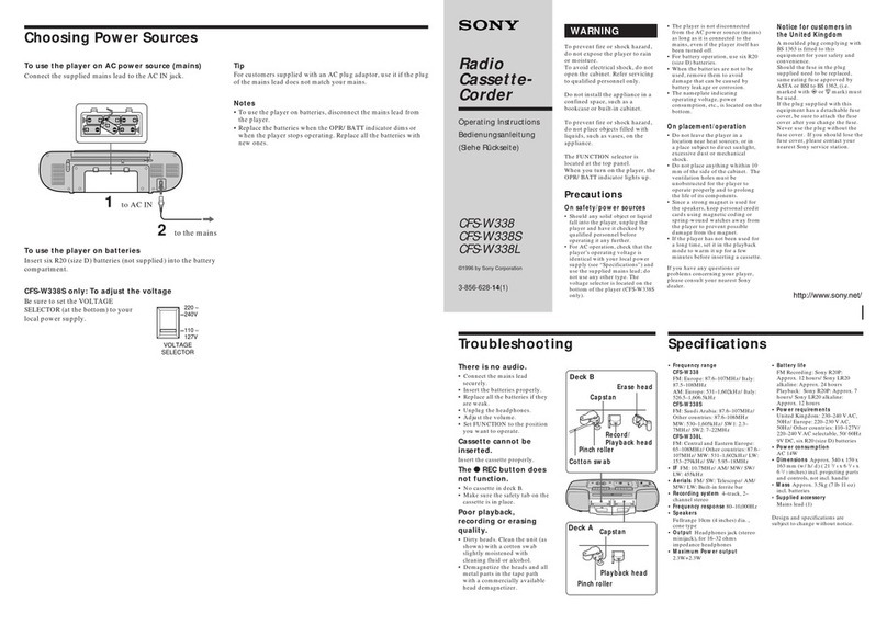
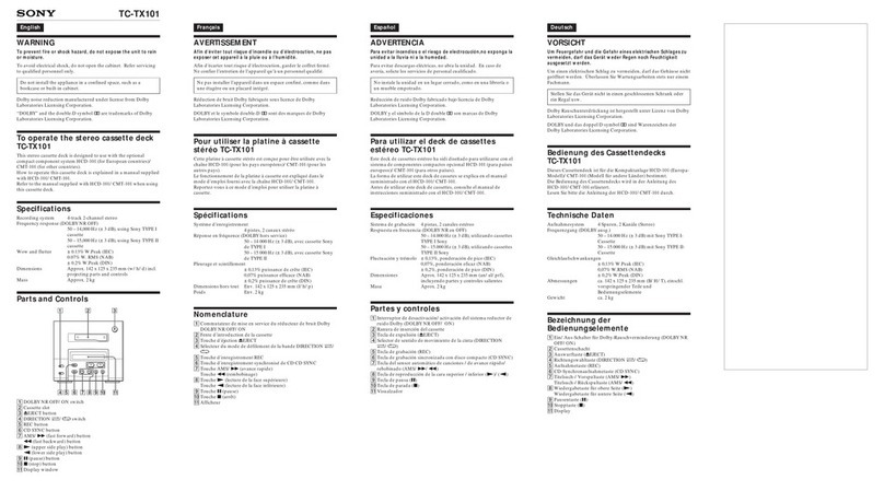
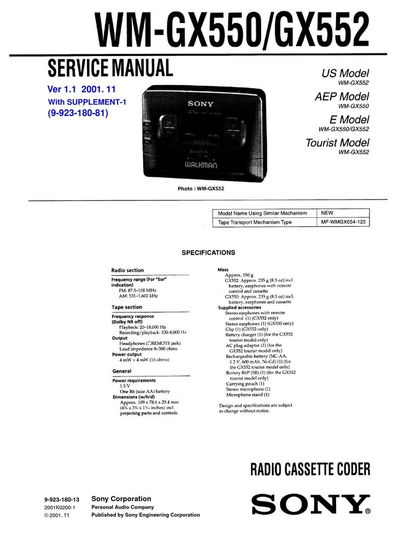
Sony MEGA BASS CFD-DW83 User manual

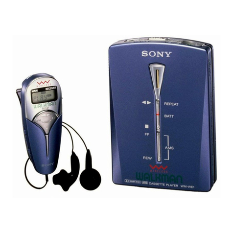
SERI|ICE
MANIJAL AEP Model
UK Model
E Model
Photo:
AEP
model n reABll$s
SPECIFICATIONS
CD
player
sectlon
Syslom Compâct
dlsc
dlgltal
audlo
system
Laser
diode
prooerties
Material:
GaAlAs
Wavolength:
780nm
Emission
duration:
Conllnuous
Laser
outout:
Less
than44.6
rrW'
'This output
is thevalue
msasursd
at a
distance
of about
200mmfiom the
objective
lenssurtacs
on lhe opticâl
pick-up
block
2OOr.p.m:
to 500r.P.m.
(CLV)
Sony
Super
Strategy
Cross
Intarlsavê
Bead
Solomon
Corde
2
20
- 20,000
Hzli dB
Below
maasurable
limit
. Toral
withTYPE
| (NORMAL)cassette:
60
- '10,000
Hz
. Playback
with
TYPE| (NOBMAL)
cassatte:
60
- 12,000
Hz
Fullrangespeakers:
10cm dia.,
Super
wooler:
I cm dia.
Full-range
speakers:
2.5W + 2.5
W (at6
ohms,
315Hz, 100/oharmonic
distortion)
Super
wooter:
7 W (at6 ohms,100Hz'
10o/oharmonic
disiortion)
Mixing
microphono
input
jack(minijack)
sensitivity
2.5 mv
Forlow impedance
microphone
Twolineinput
jacks
(Phono
jacks)
Sensitivity
0.3V
Input
impedance
47 kilohms
or higher
Headphones
jack(stereominiiack)
For16
- 68 ohmsimpedance
headohones
TwoCD output
iacks
(Phono
jack)
Load
impedance
10kilohms
or higher
Ratedoutput
'l
.26
V rmsat load
imDedance
47 kilohms
- Continued on next Page
-
Frequency
response
Speaker
Power
outpul
Inputs
Outpuls
Spindle
speed
Error
correction
Number
of channels
Frequency
response
Wowandllutter
Radio
section
Frequency
range
Antennas FM:
Telescopic
antenna
AM: Built'in
lerrite
barantenna
Tape recorder
sectlonand general
Recording
system 4-track
2-channel
stereo
Fastwinding
time Approx.
2 min withSony
casselte
C60 CD
RADIO
CASSETTE.CORDER
Model
NameUsing
Similar
Mechanism
CDSection NEW
Tape
Section NEW
9q{"3r_D_"1'j:
f3T_"_
Tape
Transport
Mechanism
Type
KSM-150BGN
-oEcr
À-
mr--ôwæPBbt
DECKB MF.DW83RP.62
Sales
areâ FM AM
AEP, UK model 87.ô
- 107
MHz 531
- 1602
kHz
Itâlian model 87.5
- 108
MHz 526.5
- 1606.5
kHz
Saudi
Arabia model 87.6
- 107MHz 530
- 'l605
kHz
E model 87.6
- 108
MHz
EF]
lMlcRoFlLM
ISONY

Powerrequirements 12VOC,
oight
R20
(slzo
O)bettorles
torCDradlocasselte.corder
4.5V
DC,thre6R6
(slze
AA)batteries
for
clocUtlmer
Batt€rylife Batt€risstor radio cassolte-corder
636.5
x211
x226 mm (w/h/d)
(25!/rx${sx9;ns6q5;
incl. poôcting parts and controls
Approx. 8.3 kg, incl. battories
(Approx. 18 lb 4.8 oz)
AC poworcord (1)
Specifications
TABLEOF CONTENTS
Title
SERVICING
NOTES
ModelIdentification
NotesonHandling
theOpticalPick-up
Blockor BaseUûit
ChuckPlate
Jigon Repairing
GENERAL
Location
andFunctionof Controls . . . . .
Section Page
1.
2.
Dimensions
Wsight
Suppliedaccsssory
Note
This appliancsconlorms with EEC Diroctivos761889
end O2l499
rsgardinginlerfsrsnce
suppression.
Designând spsciticationssubject
lo changowithout
notice.
SAFÊTY.RELATED
COMPONENT
WARNING!
t
COMPC'NENTS
IDENTIFIEDBY MARK A ON OOTTEO
LrNÊW|TH
MARK a ONrHE SCHEMAÏC
DTAGFAMS
AND IN THE PARTS LIST ARE CRITICAL TO SAFE
OPERATION. REPLACE
THESE COMPONENTS
WITH
SONY PARTS WHOSEPART NUMBERS
APPEAR AS
SHOWNIN ÎHIS MANUAL OR tN SUPPLEMENTS
PUB.
LISHED BY SONY.
Settingthe Clock
Usingthe Built-in Timer
3. DISASSEMBLY
4. ADJUSTMENTS
4-1. Mechanical
Adjustment ...... l0
4-2. Electrical
Adjustments ....... 11
Tape
Recorder
Section. ..... 11
Radio
Section .....12
CDSection .......14
5. DIAGRAMS
5
o
o
5-1. Radio,
Audio Section
Block Diagram ....
5-2. CD SectionBlock Diagram
5-3. Radio SectionPdnted Wiring Boardsand
Schematic Diagram
5-4, Tape RecorderSection
SchematicDiagram ......... 27
5-5. Power
Amp,Power
SupplySection
SchematicDiagram ......... 30
5-6. Tape
Recorder,Power
Amp,Power
Supply
SectionPdntedWiringBoards.
. . . . . . . . 33
5-7. CDSection
SchematicDiagram
......., 37
5-8. CDSectionPrinted
Wtuing
Board
. . . . . . . 4l
6. EXPLODEDVTEWS. .......46
7. ELECTRICAL
PARTS
LIST......... 56
l8
2l
Requirem€nts
UK model 240VAC.
50Hz
AEP model 220VAC.50Hz
Emodel 110-120V,
220-240VAC,
ad,iusrâbl€,
50/60H2
Power
consumptlon
UK model 30w
AEP model 28W
E model 35W
Recording Playback CD playing
SonySUM-I
(NS) approx.2.5H âpprox.2H approx.lH
SonyAlkaline
AMl (N) approx.
3.5H approx.
3H approx.I.5H
-2-

sEcTtoN
1
SERVICING
NOTES
MODEL
IDENTIFICATION
UK model
AC: 240V-50H2 30W
E SaudiArabianmodel
AC: 110
- 12O,/22O
- 240V-5O,/60H2
35W
CAUÏION
Use
of controlsor adjuslmenlsor performance
of procedures
other than thosespecifiedherein
may resultin hazardousradiation
exposure.
NOTES
ON HANDLING
THE OPTICAL
PICK-
UPBLOCKOR BASEUNIT
The laser diode in the optical pick-up block may
suffer electrostatic
breakdown
because
of the poten-
tial difference
generated
by the charged
electrostatic
load,
etc.
on clothingand
thehuman
body.
During repair, pay attention to electrostatic
break-
down and also use the procedure in the printed
matterwhlch
tsincluded
rn
the
repair
parts.
The flexible board is easily
damaged
and shouldbe
handled
with care.
NOTES ON LASER DIODE EMISSION
CHECK
The laserbeam on this model is concentrated
so
as to be focused
on the disc
reflective
surlace
by thc
obJective
lens in the optical pick-up block. There-
fore, when checking
thelaser
diodeemission.
observe
more
than
25cmawayfrom
theobjective
lens.
LASER DIODE AND FOCUS SEARCH
OPERATION CHECK
I. Turn POWER switch on with no disc
insertedand
makeFunction
switch
to CD position.
2. Openthelid for CD.
3. Turn on S702 asfollowing figure.
4. Press
) key.
5. Confirm the laser diode emissionwhile observing
the objecting lens. When there is no emission,
Auto Power Control circuit or Optical Pick-up is
broken.
Objective lens moves up and down three times for
the focussearch.
Turn on S7O2with
a slenderscrewdriver.
MODEL
NO.CFD-DW83
CD
RADIO
CASSETTE.CORDER
12V
-_ FLASHLIGHI
BATTERY
R2O
SIZEDX8 OR EOUIVALENT
4.5V
:_ FLASHLIGHT
BATTERY
(COMPUTER//CLOCK)
R6 SIZE
AAX3 OR EOUIVALENT
MADEIN JAPAN
AEPmodel
AC: 220V-50H2 2B\N
-3-

CHUCK
PLATEJtG ON REPAIRING
On repairing CD section, playing a disc without the
CD lid, useChuck Plate
Jig.
. Code
number
of Chuck
PlateJig:
X-4918-255-l
NOTE ON REPAIRING
The spindle
motor (M702) and
theturntable
assem-
bly are
individually
supplied
as
repair
parts.
When repalringM702, please
order the turntable
assembly
together.
Dimension
isas
follows.
i9.410.lmm
spindle
molor (M7O2)
-4-

CFD-DW83
Ëe
9l
;E T
>;- - ='
Eg:ËE
E;:ii
c g
i:ë
Ë
Elg'e
;EiËE
+ËieF
eËE'i
Ë
iË!-EÊ
o
I
z
g
à
ï
€F
Eç
Eo
Ëst
2
3
s
.ç
6
t
à
E
Po
4=
>E
a-E;;
=P *
-f
Es
o Adt
eË Ia
âo =d
Ef "3Êà: E2z
EË E=E=
ag à.:
èË
ËË=Ëg*È
Ë
ÊËliE fi
=ù B Èôtr à
P
la
'.F,9
El/^r
+)
st p
9E rr 1
oË Y
ô9 3l
:-g i I
CD
2nt
=Ê
N*
{ ---r-
E ,Ë:àl
HIF
EË -;';
:3
I
-tP
È;

o
ô^
gË t
29
:g
è
.0
9!
tÈ
çÈ
;
Â
e
È
o
=
Ë:
êE
ÈË è
'EE"E
c> I :
Ë8È:
r3ÉE
<ir ç !r,
3cÈâ
E= 5
-
3
i
ËF
-:_ P
:8aË
Ë E€ g
ç tË *
Ën!isE
E F...!:sg
ËË!iiiiÏi
2
a
E
E
:
',
8.9 a
F=Ë
lÈ sE
h :r =È
; :g ;r
:;sÈËunË
.Eo'fi'?^
u-l = ^ r ^ i I
E
o
s
E
, 96
s ià
9 E;
s fÈ e
ËB Ë
ÊE:
!e €
rts
tÉl
I Ol
t6l
I!,I
l.')l
tol
tql
tot
tclj
LI
sEcTtoN
2
GENERAL
r
E
è
u,
F
a
E
;.o
-o
o
.9
;
o
0
J
(J
-
9 >9
Ë B€
ËaÉ!
> R(,)€
ËÈ?ÈgÈ
Ë;ËËEgË
I
o.g ô
Ez Âa
Ë "
Ë
i
gË
. : ç e
à€
a 6 :;:ۈ
! T HèJ;t
â Ë êEEÈE-
s t Ê:Ë$s*
3;E
sËËËËË'
g slËËËPrFE
i 42;EP-
ë;
È 3i'ââai33
t
I
!
.3
o
5.
È;
9eE
!Je
FEË
E:E
Ex*È*
,:e
e
g
Ë!
ËË
z
ô
Èi
5E
'6E
Ëg
Èts
lz
^ Y=
c9;ii
; tàêa
;;;rvo
Eu
50
è9
iz
aâ
Ë
@
0
-
Pu
-n>
ht: è9
t:J :i ==
tLq '' Ȁ
r.sr p È
-5-

4.2. ELECTRICAL
ADJUSTMENTS
TAPE RECORDER
SECTION
PRECAUTION
l. Adjustments should be performed in the order
given.
Generally playback circuit adjustments should be
completed before performing recording circuit
adjustments.
2. Adjustments should be performed for both L ch
and R-ch.
Switches and controls should be set as follows
unless
otherwisesPecified.
a Positionsof switches
and control knobs
FUNCTION ....... TAPE
ISS ... .....2
DIRECTION
MODE,. .... ?
GRAPHTC
EQUALIZER... ' mechanical
center
MEGA BASS . . scale5
BALANCE . mechanical
center
odB- 0.775V
Frequency difference between FWD and REV should be within
r.5%.
Adiusimont Localion: TC board
Short-circuil with
a screwdriver
for the
highspeedadjustment.
ad-
the
\
CNP121_L
TÏ
,uilZ
o'c*
e{
Eyi33i
ii?;idt</
n.n, o I RV308 (normal)
"-''' " I RV309 (hish)
-
Tope
speed
Adlustment
FEEK Al TDFCK
Bl
Procedure:
Mode : FWD playback
test
tape
ws-48A
(3
kH2.0dB)
Perform high speed
iustment
Play back the test
specifications
below.
Adiustm€nt
Valuer
speed
checker
or
32l? trequency
counter
PHONES
jack
adjustment before mormal speed
tape WS48A and adjust to meet
speod deck Adiustmenl
pan t€st
pin
cN121
speedchscker
heading
frrquancy
counlea
reading
high RV307 short 4.17to
+O.l'77"
6,000t
10Hz
BRV3O9
normal RV306 open -0.1'7
ro
+O.l'l% 3,000t5
Hz
BRV308
a Standa
rd input level
Input Pin Mtx Mlc LINE
IN
Signalsource
imPcdance 300
n10kn
lnput signallevel 0.775
mV
(-60 dB) 0.436
V
(-5 dB)
Frequency I kHz IkHz
a Standard
output level
Outpul Pin SP OUT (L.R} PHONES
Signal
source
impedance 6s} 32n
Output signâl
level 0.775
V
(0dB) 0.245
V
(- 10
dB)
. Test
tape
T6st Tapo Signâl Usedfor
ws48A 3kHz,
0dB Tape speedadjustment
P4-A063 6.3
kHz,
-10
dB Headazimuth adiustment

Record,/Playback Head Azimuth Adjustment
lpFcK
Al l-pFcK
Bl
Procodure:
l. Mode: FWD playback
testtape
P4-A063
(6.3
kHz,
-10
dB)
RADIO SECTION
See
page
13for AdjustmentLocation.
FUNCTIONswtich: RADIO
IAM]
BANDswitch:AM
FM
RFSSG Put th6 lêad-wirs
antenna closg to
ths sst.
t
pHONES
iack
Turn the adjustmentscrew for the maximum output
levels.If theselevelsdo not match, turn the adjustment IFM]
30% amplitud€
modulation by
400 Hz signal
Output level:
aslow as
Possible
BANDswitch: FM
22.5 kHz lr€quency
dsviâlion by 400 Hz
srgnal
Output level:
as
low as
possible
ro
CN3
(ANT
IN)
. Rcpcat thc procedurc3 in cach adjustmcnt
severaltime3,and thc frcqucncy covcragcand
lrackinS
adjustmcntsshould
bc finallydoncby
thètrimmer
câpacitors.
3. Phase Check
Mode : playback
lesÎ lape
P-4.AO63
(6.3
kHz,
-10
dB)- _
LCH
Screon
pattorn
e@@os
In ph.. 46. 90. r36c t8O.
good vaonS
4. Set in the REv mode
and repectthe slep I to
3.
5. After the adjustment,
lock the screws with locking
compound,
Adjustmsnt Locltion : Record,/Playback head
AM RF SSG
o6cillo6copa
PHONES
jack
PHONES
jack
AM FREOUENCYCOVERAGEADJUSTMENT
Adjust for a maximum readina on VTVlvl
T1 Ercept ltaliatr: 518 kHz
Italiar | 516 kHz
cT14 Except Italian : 1,680kHz
Italian: 1,630kHz
AM TRACKINGADJUSTMENT
Adiust for a maximum readins on VTVI\4
620 kHz
cT1-3 1.400 KHz
FM FREOUENCYCOVERAGE
ADJUSTMENT
Adjust for a maximum reading on VTVIVL
L2 E : 86.5 MHz
AEP, UK, Italian, Saudi Arabia: 87.35 MHz
ctt2 E : 109.5MHz
AEP.
ItK, SâudiArabia: 107.8MHz
Italian: 108.25MHz
FM TRACKINGADJUSTMENT
Adjust for a maximum readirg on VTVlvl
L1 E : 86.5 MHz
AXP, IrK, Italian, Saudi Arabia: 87.35 MHz
cT1-1 E : 109.5 MHz
AEP. IIK. Saudi Arabia: 10?.8 MHz
Italian : LO8.25M}Iz

oIFM VCO ADJUSTMENTI
Procaduro:
FM NF SSG
0.AOl
pF rctoin@
C.rrirr Frcqurncy: Accordingto the color of the mark on
ceramic
filter (CF2).
Output L!v.l: 80 - 90dB
1) Adjust with RV1 so that the readingon the frequency
counter
becomes?6.0
t0.3 kHz.
IAdjustments
Location]
Adiustment Locationl
IRsdio Boârdl
AM TrackingAdiudmont
cT1.3
L1 cTl.1
FM Trrckino Adiunment
o
FM
Frequency
Covrraga
Adiunm.ni [crt-z
tLz-
isas:i
M.rk Crraiar Frtquancy
red 10.7 MHz
blue 10.6?MHz
orange 10.73
MHz
black 10.64MHz
white 10.76MHz
-13-
o

lîosecrroNI
NotesonAdjustment
l Performadjustmentin servicemode.
After adjustment,be sure to releaseservice
mode.
Perform
adjustments
in theorder
given.
Usethedisc
(YEDS-I
8,PartNo.3-702-10l
-Ol
)
only when
so
indicated.
BeforeAdjustment
Put the set into servicemode and perform the
followingchecks,Repairif there
are
any
problems.
o Sled
MotorCheck
1 Press
) key-+1 ç"t.
2. PresslN,
K{ keysand confirmthat tlre'FOP
moves
smoothlyfrom the innermost
to outer-
most circumference
and back smoothly and
with no catching
orabnormalnoises.
>> : FOP
movesto theoutercircumference
l( : FOPmovesto theinnercircumference
. Focus
SearchCheck
l. Press
) key. (Focus
searchoperationis per-
formed
continuously.)
2. Look at the FOP objective
lens
and confirm
that it movesup anddownsmoothly,with no
catchingor abnormalnoises.
3. Press'I key.
Confirmthat focussearchoperationstops.If it
doesnot,pressI keyagainlonger,
Howto Put
the
SetintoServicêMode
l. Short-circuit
following
portions
onthe
CDcontrol
board.
2. Turnthe
POWER
on.
.,
3.
o
VCO
Adjustment
Adjustm€nt Procedure:
l. Short-cfcuit@ portionon CD mainboard.
2. Adjust with RV703 so that the readingon
frequency
counter
becomes4.3218MHz.
3. Releasetheshort-circuit
@ portion.
Adjustment Location: ICD
Main
Boardl
frequency counter
-14-

sEcTloN
4
ADJUSTMENTS
4-1. MECHANICAL
ADJUSTMENT
TAPE
RECORDER
SECTION
PRECAUTION
l. Clean the following parts with a denatured-
alcohol-moistened
swab:
record/
play
back
head pinchrollers
erase
head
capstans
2. Demagnetize
the record/playback/erase
head
with
ahead
demagnetrzer
'
3. Do not use â magnetized
screwdriver
for the
adjustments.
4. After the adjustments,
applysuitable
locking
com-
pcund to theParts
adjusted.
5. The adjustments
should
be
performedin the order
given
in this servlce
manual'
rubber
belts
idlers
Head
Height
Adiustment
Adjustment Procedure:
l. Insert
a
mirror cassette
CQ-009C
2. Make
theset
to FWD playbackmode'
3. Loosen the FWD tape guide fixing screw and
adjust with inserting the adjusting shim to elimi-
nate tape curl and tape twist in the portions of
tape
guide
and
head.
4. Make
theset
to REV playback
mode
5. Loosen the REV tape guide fixing screw and
adjust with inserting the adjusting shim to climi-
nate tape curl and tape twist in the portions of
tape
guide
and
head
6. After adjustment, apply suitable locking com-
pound to thefixingscrews
Adjustment Location:
head height adiusting head height adiusting
shim (Bi shim (L)
Part No.
3344-',766-0r 0.1
3-344-',166-\t 0.2
3-344-'766-3r0.3
Pan No. t
l-344-765-01 0.1
3-344-'165-rr0.2
3-344-'165-2r 0.3
Torque
Measutement
Modo Torqua mator Mrlor rrading
FWD cQ-102C
25to55gcm
(0.34
to 0.?6
ozinch)
FWD
back
tension 3.0
to
5.0
g
cm
(0.04
to 0.06
ozinch)
REV cQ-lo2RC
25to55gcm
(0.34
to 0.76
ozinch)
Rllv
back
tension 2.5
to
5.0
g
cm
(0.04
to 0.06
ozinch)
FF cQ-201r) 80
to 135
8
cm
(1.10
to 1.84
oz'inch)
REW cQ-201
ll 80
to 135
g
cm
(1.10to 1.84
ozinch)
Tape
Tension
Modo Tonrion mol6t M6tor roading
t:wl) cQ-4034 more
than
110
g
(more
than
3.88
oz)
REV cR-403
R
-10-

DIAL CORD
STRINGING
1. Preparation
lens
ton
500
s
I
2.
ft
._LM
Setting
Setthe dial poinrer to the
left sideof threescratched
lines.
Q Suspend
the fixing plare
of rhe
dial cord to the sprlng
666 16"
spring
to th€
dial
drum.
@ Setthe diat cord ro the
dial
pointer.
OTurn rhe variabte
capacitor
shafrTu y clockwise(MAX).
@ fit ttredial drum to the variable
capacitor
shaft.
@Turn thevariable
capacitor
shattîully counrerclockwise
(MlN).
O +BVTP3
x t2 (7
pcs.) o
O tgz.o
" 6
dial
drum
-7lD Aoolvsuitabte
#"kinscom'ound
(O Set rhe dial
pointer to
TU chassis.
TU chassis
M
IN.
MAX.
DialCord
Stringing
-9-

TC BLOCK @ screw
+BVTP3
x 12
12
pcs.l
O screw
+BVTP3
x t2 (4
pcs_)
c
CD BLOCKAND CD CONTROL
BOARDASSEMBLY
o iïiîr., 12
(3pcs.)
3. Dial
Poir
OïTTîrg*s
rr
p".r
CO coôtrol board
assembly
o
screw'
+BVTT':
3x5 \l
(1pc.) '
-ra1;
/e 2'.
'./

FRONT CABINET
ASSEMBLY
v<-:-4\2
\r".4 r4"-' .l
---\1 .,/'15 ,/... ->,\ .' ty'
<a)
il\-+-t )'16.,9,4
<,
sEcrloN
3
DISASSEMBLY
Note: Follow the disassembly
procedurein the numerical
orcler
glven'
G)
cN510
(YE
L)
OcNslo
(R
ED)
o
screw
''r/l\
/'1,,1
6l
screw
.+BVTP3
{4
pcs.l x12
SCrew
+BVTP3x 62 (5pcs.l
--\
O batlery case
lid
o
screw
+BVTP3x 62 (4
pcs.) +BVTP3x 12
{1
pc.l
(baltery
compartment)
lA rear
cabinet
assembly
olîiir.xr2 (4pcs.)
o
screw
+BVTP3x 12 (1
@ tuning Knoo
UPPER I
CABIN
fine knob spacer
uppercabinetassemblY
ET ASSEMBLY
Q volume
xnob -À I
,"4
/.J I
olîïËr. *u,,
REAR CABINET
4ej
\z-x\
\[\ \\
antennalead.

D
I
t
D
E-F Balance
Ad,ustment
-fhis
adjustn)ent
isto bedone whenthe optjcal
blockisreplaccd.
Adjrrstment
Procedure
:
otcilloscopo
(OC range)
CD RF boar.l
TEUC70l
VÊEF (IC7OI
l. Connect
Focus
Bias
Adiustmenl
This adjustmentis to be done when the optic l
block isreplaced.
Adjusftnent
Procedure:
oscilloscopo (DC rcùgc)
CD nF boatd
RFo
(tc7ot@
1REF
(tc7ot @))
1. Connect the oscilloscope
between
IC70l pins
@a.o
@.
2. Put the setinto service
mode.
3. Pressthe )N and K< keys to move the FOP to
the center. (Move the FOP to the music area
on the disc to enable easy
visibility of the eye
Pattern
)
4. Insert
disc
(YEDS-18)and
press
) key.
5. Adjust RV?02 so that the oscilloscope wave-
form is asshown in the figure below (eye pat-
tern
).
A good eye pattern means
that the diamond
shape
(O) in the center of the waveform can be
clearlY
distinguished
6. Release
service
mode âfter adjustment
is com-
pleted.
a RF signal
reference
waveform (eye pattern)
E
@
@
the oscilloscope
betweenIC?01
pins
@
2
3
4
5
voLT/OlV:0.2v
TtME/OIV
:500ns
0.8-
1.5Vp-p
When observing the
scope for AC range eye pâttern, set the oscillo-
and raise vertical sensitivity.
VREF:E-F
Eslanco
Adiustm.nt,
Focus
Biss
Adjusrment
olcilloscoee
(Q) side)
@ un,l
Puttheset
into service
mocle.
Pressthe >N ând
K< keys to movethe FOPto
thc center.
Insert
dlsc
(YEDS-18)
and
press
) key
Adjust RV?01 so that tlle oscilloscope
traverse
wavefornt
is
synrmctrical,
as
sltown
in the figttrc
below.
Release
service
mode after adjustment
is conl-
pleted.
A= I
VOLT/DIV: 1V
TIME/DlV: tms
Adjustment Location:
RV702:
Focus
Biss
Ad
justmant
RFO: Focus
BjQt
Adiustment,
oscilloscope
((+ ) sid€)
TE: E-F BalançQ
Adiudmont,
oscilloscope
((+ ) sid6)

*:(rÊc DEsrox Tlo i2o)
| .Pcs, r2v
| | crrool
' AEP,UK,lT,MODEL
I | ^c lx I
t1,IT tl^r{ ||oo€t
€^,3AUD| li^ll^ T.OOCL
f- ---- ------ ------ ---
_L (|Ec
T
a
DECK-A
FoÆl
I
rrè"

Focus/Tracking
Gain
Adlustment
A frequency response
analyzer
is necessary
in
order
toperform
thisadjustment
€xactly.
However,this gainhasa margin,so even
if it is
slightlyoff, thereis no problem. Therefore,do not
perform
this
adjustment.
Focus/tracking
gain
determines
the
pick-up
follow-
up (vertical
and horizontal)
relative
to mechanical
noise
and
mechanical
shock
when
the2-axisdevice
opera
te.
However,
asthese
reciprocate,
the
adjustment
is
at
the
point
where
bothare
satisfied.
a When gain is raised,
the noisewhen the 2-axis
device
operates
increases.
The following is a simple adjustment method.
- Simple Adjustment ,
Note: Since
exact adjustment cânnot b€ performed,remem-
ber the positions
of the controls
before
performing the
adjustment. lf the positions after the simpleadjust.
ment are only a little different, return the clntrols to
the originalposition. oscilloscope
(DC range)
TE
?EF
neSi
es{
It br
axls
Ot--
o-
t horl
tis
pe
rf,
oeYlc
I
I
Whengain is lowered,
it is more susceptible
to
mechanical
shock
and
skipping
occurs
moreeasily.
When
gain
adjustment
isoff, the
symptomsbelow
appear.
l.
2.
J.
VR
Keep
th
/lf thr
lcanno
\the2r
: ser
set
be
xls
(
ltz
nl
for
:o
ntal.
ot horizontal,
thisadjustment
l
rmeddue
to the
gravity
aeainst/
Insertdisc
(YEDS-18)
and
press
)pLAy button.
Connectoscilloscope
to main
ampboard
FE.
AdjustmentRV705 so that the waveform
is as
shownin thefigurc
below.
(focus
gain
adjustment)
VOLT/DIV:
TIME/DIV: 100
mV
2mS
lOOmV
OV
Incorrent
Examples
(DC
onadjustedwaveform) level
changes
more
than
VOLT/DIV:
TIME/DIV: IOO
mV
2mS
25O
mV
OV
high focus gain VOLT/DIV: t0O
TIME/D|V: 2 mS
lO0
mV
75
mV
Grin
Symptomc Focur ï?rcking
. Thctimeuntilmusicstarts
becomcs
longerfor STOP
+> PLAYor
automatic
s.lcction(laa, r buttons
Presscd.
(Normally takes
about
2s€conds.)
low loworhigh
oMusicdoesnotstÂrtand
dkccontinucsto rolale
for STOPI) PLAY or
automatic
selcction
(
FK
)}l buttonspressed.)
low
. Sound
isintcrruptcddur-
ing
PLAY. Ortimccount-
erdisplaystops
progress-
lnt.
low
. More
poise
durint 2-axis
deviccop€Iation. high high low focus gain

CFD-DW83

l-
I
I
s303-1
Fufr-Cnt
F;i;rc:l Fam;l
X-F
\srERËo/
:rl
rD .l I
n^.ot
I
."'5s."o
FuNcl toNl
I
I
LIXE IN
I
<- rlo
."J:*"@
OECK-B
I
t
;l
r
-19-

cFD-DW83
5"1. RADIO,
sEcrroN
5
DIAGRAMS
AUDIO SECTION
BLOCKDIAGRAM
EA: SaudiArabia model
lT : ltalianmodel
fi=--i;rL
""'ië',6
HEso' -i
ER^EG 'rE^o tr9 t
T
I
I
R-CH, S,r!Ë ^s L-Cl
Table of contents
Other Sony Cassette Player manuals

Sony
Sony Walkman WM-FX491ST User manual

Sony
Sony CFM-30TW Marketing User manual

Sony
Sony WM-GX510 User manual

Sony
Sony CFS-W338 User manual

Sony
Sony Sports Walkman WM-FS593 User manual

Sony
Sony CFM-2300 User manual

Sony
Sony TC-K511S User manual

Sony
Sony Walkman WM-FX522 Setup guide

Sony
Sony Walkman WM-FX355 User manual

Sony
Sony Walkman WM-D6C User manual

Sony
Sony CFM-20 User manual

Sony
Sony Walkman WM-GX674 User manual

Sony
Sony TC-150 User manual

Sony
Sony Walkman WM-FS222 User manual

Sony
Sony TC-KB920S User manual

Sony
Sony Walkman WM-EX372 User manual

Sony
Sony WM-AF62 User manual

Sony
Sony TC-RX410 User manual

Sony
Sony TC-K81 User manual

Sony
Sony TC-W21 User manual