Sony RB1G User manual

Version Date Subject
1 2/2013 1st Issue.
2 7/2013 Part Information Addition :
i) New model addition (Pg 246~468)
ii) Update Board Name Matrix (Pg 15, 16)
3 7/2014 Update Troubleshooting Flow LCD TV
9-888-140-03
For SM - Unique , please refer :
9-888-140-Px ( Pan Asia )
9-888-140-Cx ( China )
9-888-140-Ax ( America )
9-888-140-Jx ( Japan)
9-888-140-Ex ( Europe)
HISTORY INFORMATION FOR THE FOLLOWING MANUAL:
RB1G CHASSIS
Segment: LW
SERVICE MANUAL (COMMON)

LCD TV
RB1G CHASSIS
Segment: LW
SERVICE MANUAL (COMMON)
Pravin Mevada

3
MODEL LIST
THIS SERVICE MANUAL CONTAINS COMMON INFORMATIONFOR BELOW REGIONSAND MODELS:
MODEL
KDL-32W600A KDL-32W654A KDL-42W650A KDL-42W656A
KDL-32W603A KDL-32W655A KDL-42W651A KDL-42W657A
KDL-32W605A KDL-32W656A KDL-42W653A KDL-42W658A
KDL-32W607A
KDL-32W650A
KDL-32W651A
KDL-32W658A
KDL-32W670A
KDL-32W674A
KDL-42W654A
KDL-42W655A KDL-42W670A
KDL-42W674A
KDL-32W653A
REGION
ASIA CHINA AMERICA JAPAN EUROPE

SectionTitle Page
1. SAFETY NOTES
1-1. Warningsand Caution………………………………………………………. 5
1-2. Caution Handling of LCD Panel ......…………….................................... 5
1-3. SafetyCheck Out ........................……………......................................... 6
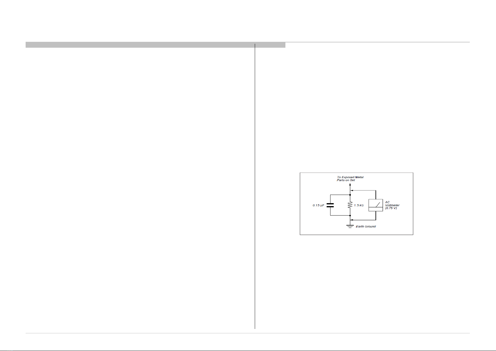
1-4. Leakage Test .......................................................................................... 6
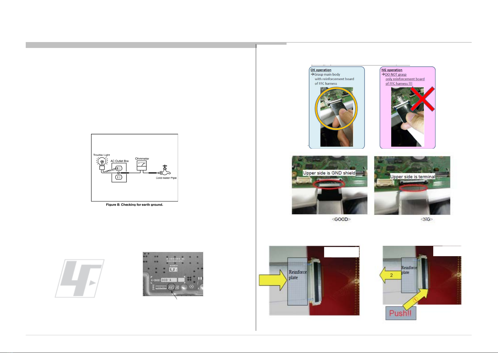
1-5. How to Find a Good Earth Ground………………………………………… 7
1-6. Lead Free Information….…………………………………………………… 7
1-7. Handling the FlexibleFlat Cable (FFC)……………………………………. 7
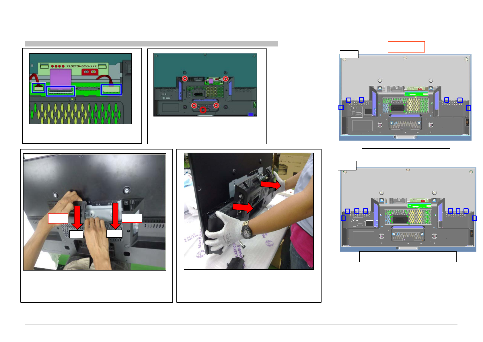
1-8. Method to Disassemble Bracket Top & Chassis Box…………………….. 8
1-9. Method to handle Chassis Box……………………………........................ 10
1-10. Instruction about Disassembling Smart Core……………………………... 11
2. SELF DIAGNOSTICFUNCTION
2-1. Overviewof Control Buttons ................................................................... 14
2-2. LED Display Control ………..................................................................... 15
2-3. LED Pattern………………........................................................................ 15
2-4. Standby LED Error Display…………………………………………………. 15
2-5. Triage Chart ............................................................................................ 16
3. TROUBLE SHOOTING
3-1. No Power…….……………………………………………………………….. 17
3-2. LED Blinking……………….………………………………………............... 33
3-3. No Sound……………………………......................................................... 62
3-4. Analog Signal Path.................................................................................. 116
3-5. No Picture................................................................................................. 117
3-6. Input Skip Function……………………………………………………. 203
3-7. SideButtons Malfunction……………………………………………………. 204
3-8. IR Remote Commander Malfunction………………………………………. 205
3-9. Light Sensor Error…………………………………………………………… 206
3-10. Network Malfunction:Ethernet (Wired)……………………………………. 207
3-11. Wireless Network Malfunction……………………………………………. 211
3-12. BluetoothMalfunction…………………………………………………. 213
3-13. 3D Glasses (Active)Malfunction…………………………………………… 214
3-14. HD Rec Malfunction……………………………………………………….. 215
3-15. Android Application Malfunction…………………………………………… 215
4
TABLE OF CONTENTS
Please refer ServiceManual – Unique for below information:
-SafetyWarnings
-WireDressing
-Circuit Board Location
-Disassembly and ExplodedView.
Section Title Page
4. SERVICE ADJUSTMENTS
4-1. Accessing Service Mode
.....................................................................
216
4-2. Transition of Each Micro’s ServiceMode……….………………………
216
4-3.
Change Data by ServiceMode 1…………………………………..…….
216
4-4. SaveChanging Data by Service Mode 1……………………………… 216
4-5. Change Data by ServiceMode 2……………………………………….. 217
4-6. SaveChanging Data by ServiceMode 2……………………………… 218
4-7. Restore WB/GammaAdj. Data to B Board……………………………..
219
4-8. WB Adjustmentby ServiceMode………………………………………..
219
4-9. VCOM Adjustment (NFR-AUO Panel) ………………………………….
220
4-10. VCOM Adjustment (HFR-SDC Panel) ………………………………….
221
4-11. REC Setting………………………………………...................................
221
4-12. Reset Panel OperationTime……………………………………….........
222
4-13. Set to Shipping Condition………………………………………..............
222
4-14. Summary of Service Control
………………………………………..........
222
4-15. ServiceMenu Tree………………………………………........................
223
4-16. How to Enter Self Diagnosis Display
……………………………………
224
4-17. Updatingthe software……………………………………………………. 226
4-18. Non network function…………………………………………………….. 226
4-17. One Step Touch Key function (not applicable for this model………… 228
5. DIAGRAMS
5-1. Circuit Board Location
.........................................................................
229
5-2. Block Diagram......................................................................................
230
5-3. Connector Diagram ………………………………………......................
237
RB1G CHASSIS
W600A/ W603A/ W605A/ W607A/ W650A/ W651A/ W653A/
W654A/ W655A/ W656A/W657A/ W658A/ W670A/ W674A

RB1G CHASSIS
W600A/ W603A/ W605A/ W607A/ W650A/ W651A/ W653A/
W654A/ W655A/ W656A/W657A/ W658A/ W670A/ W674A
5
SAFETY NOTES
SECTION 1
1-2. Caution Handling of LCD Panel
Whenrepairing the LCD Panel, make sure you are groundedwith a wrist band.
Whenrepairing the LCD Panel on the wall, the panel must be securedusing the
4 mounting holes on the rear cover.
1) Do not press the panelor frame edge to avoid the risk of electric shock.
2) Do not scratch or press on the panelwith any sharp objects.
3) Do not leave the module in high temperature or in areas of high humidity for
an extendedperiod of time.
4) Do not expose the LCD panel to direct sunlight.
5) Avoid contactwith water. It may cause short circuit within the module.
6) Disconnectthe AC power when replacing the backlight (CCFL) or inverter
circuit. (High voltage occurs at the inverter circuit at 650Vrms)
7) Always clean the LCD panel with a soft cloth material.
8) Use care when handling the wires or connectorsof the inverter circuit.
Damaging the wires may cause a short circuit.
9) Protect the panel from ESD to avoid damaging the electronic circuit (C-MOS).
10) During the repair, DO NOT leave the PowerOn or Burn-in period for more
than 1 hourwhile the TV is face down on a cloth.
1-1. Warnings and Caution
1) These servicing instructions are for use by qualified service personnelonly.
2) To reduce the risk of electric shock, do not performany servicing other than
that contained in the operating instructionsunless you are qualified to do so.
3) An isolation transformershould be used during any service to avoid
Possible shock hazard, becauseof live chassis. The chassis of this receiver is
directly connectedto the ac power line.
4) Be sure to follow these guidelines to protectyour property and
avoid causing serious injury :
• Carry the TV with an adequatenumber of people; larger size TVs require
two or more people.
• Correct hand placement while carrying the TV is very important for
safety and to avoid damages.
5) Componentsidentifiedby shading and mark on the exploded views,
and in the parts list are critical forsafe operation.Replace these
componentswith Sony parts whose part numbers appear as shown in this
manualor in supplementspublished by Sony. Circuit adjustmentsthat are
critical forsafe operation are identifiedin this manual. Follow these
procedureswhenevercritical componentsare replaced or improper
operation is suspected.
!
Figure 1. TV is faced down on a cloth during repair.
Do not leave Power ON > 1 hour

RB1G CHASSIS
W600A/ W603A/ W605A/ W607A/ W650A/ W651A/ W653A/
W654A/ W655A/ W656A/W657A/ W658A/ W670A/ W674A
6
1-4.Leakage Test
The AC leakage fromany exposed metal part to earth ground and fromall
exposedmetalparts to any exposedmetal part having a return to chassis must
not exceed 0.5mA (500 microamperes).
Leakagecurrent can be measured by any one of the three methods:-
1) A commercial leakage tester such as the SIMPSON 229 or RCA WT540A.
Follow the manufacturersinstructionsto use thoseinstructions.
2) A battery-operatedAC milliampmeter The DATA PRECISION 245 digital
multimeter is suitable for this job.
3) Measuring the voltagedrop across a resistor by means of a VOM or battery
operatedAC voltmeter. The 'limit' indication is 0.75Vso analog meters must
havean accurate low voltage scale. The SIMPSON'S 250 and SANWASH-
63TRD are examples of passive VOMs that are suitable. Nearly all battery
operateddigital multimeter that have a 2 VAC range are suitable.
(see Figure 2.)
1-3 Safety Check-Out
Aftercorrecting the original service problem, performthe following
safetychecks beforereleasing the set to the customer:-
1) Check the area of your repair for unsoldered or poorly soldered
connections.Check the entire board surface for solder splashes and bridges.
2) Check the inter board wiring to ensure that no wires are pinched or
contact high-wattageresistors.
3)Check all control knobs, shields, covers, ground straps and mounting
hardware have been replaced. Be absolutely certain you have replaced all
the insulators.
4) Look for unauthorizedreplacement parts, particularly transistorsthat
were installed during a previous repair. Point them out to the customer and
recommend their replacement.
5) Look for parts which, thoughfunctioningshow obvious signs of
deterioration. Point them out to the customer and recommend their
replacement.
6) Check the line cords for cracks and abrasion. Recommend the
replacement of any such line cord to the customer.
7) Check the antenna terminals, metal trim, metalized knobs, screws and all
other exposed metal parts for AC leakage. Check leakage test as described
next.
8. For safety reasons, repairing the Power board and/or Inverter board is
prohibited.
Figure 2. AC voltmeterto check AC leakage
Safety Notes

RB1G CHASSIS
W600A/ W603A/ W605A/ W607A/ W650A/ W651A/ W653A/
W654A/ W655A/ W656A/W657A/ W658A/ W670A/ W674A
7
1-6. Lead Free Information
The circuit boards used in thesemodels have been processed using Lead
Free Solder. The boards are identifiedby the LF logo located close to the
board designation.
1-5. How to Find a Good Earth Ground
1) A cold-water pipe is a guaranteedearth ground;the cover-plate retaining
screw on most AC outlet boxes is also at earth ground.
2) If the retaining screw is to be used as your earth ground,verify that it is at
groundby measuring the resistancebetween it and a cold-waterpipe with an
ohmmeter.The reading should be zero ohms.
3) If a cold-water pipe is not accessible, connecta 60- to 100-watt trouble-
light (not a neon lamp) between the hot side of the receptacleand the
retaining screw. Try both slots, if necessary,to locate the hot side on the line;
the lamp should light at normal brilliance if the screw is at ground potential
(see Figure 3).
Figure 3. Checking for earth ground.
Figure 4: LF Logo Figure 5: LF logo on circuit board
The servicing of these boards requires special precautions.It is strongly
recommendedto use Lead Free Soldermaterial in orderto guaranteeoptimal
quality of new solder joints.
1-7. Handling the FLEXIBLE FLAT CABLE (FFC)
When you insert / pull out FFC, please grasp a reinforcementboard and main body of
FFC.
< Insertion> <Pullout>
Main Board
Safety Notes
Main Board
Please hold reinforcement board and
plunge it to depths. Please pull out FFC while pushing the
button of both ends at the same time.

RB1G CHASSIS
W600A/ W603A/ W605A/ W607A/ W650A/ W651A/ W653A/
W654A/ W655A/ W656A/W657A/ W658A/ W670A/ W674A
8
Safety Notes
1-8. Method to disassemble Bracket Top and Chassis Box
1-8-1 . Method to disassemble Bracket Top
1. Remove One Screw from Bracket Top. 2. Highlighted is the hook area.
Bracket Top
3. Side view of Bracket Top hook area .
4.Pull Bracket Top at the hook area to make a
gap.
Pull
6.Take out Bracket Top.

RB1G CHASSIS
W600A/ W603A/ W605A/ W607A/ W650A/ W651A/ W653A/
W654A/ W655A/ W656A/W657A/ W658A/ W670A/ W674A
9
Safety Notes
1. Remove 3 connectors
1-8-2 . Method to disassemble Chassis Box (Standing)
2. Remove 5 screws from Chassis Box.
CAUTION
3. Pull opening of Bracket Top area to make gap from
Chassis Box top edge.
Then insert fingers to top edge gap and pull Chassis
Box to release hooks, one side(1 or 2)at one time
4. Take out Chassis Box
42”
Make sure 42" got 8 hooks
32”
Make sure 32" got 6 hooks
Pull
Pull
2
1

RB1G CHASSIS
W600A/ W603A/ W605A/ W607A/ W650A/ W651A/ W653A/
W654A/ W655A/ W656A/W657A/ W658A/ W670A/ W674A
10
Safety Notes
1. OK Position to hold
1-9 . Method to Handle Chassis Box
2. NG Position to hold.
RESTRICTEDAREA
RESTRICTEDAREA

RB1G CHASSIS
W600A/ W603A/ W605A/ W607A/ W650A/ W651A/ W653A/
W654A/ W655A/ W656A/W657A/ W658A/ W670A/ W674A
11
Safety Notes
1-10. Instruction about Disassembling Smart Core (LW Segment)
1. Detach Main Harness Lock from Panel
Lay the display face down on a work surface that is
lager than the TV and makespace in front of ORNAMENT
ORNAMENT
Recommended disassemble position
Detach main harness
lock
2. Remove Smart Core Unit from SET
Unlock from hook
Rotate to direction
3. Wipe“Scratch Marks” on Bezel Frame
Scratch marks by Smart Core remain on BEZEL flame.
Wipe off Wipe off
4. DetachMain Harness Lock
Detach main
harness lock
5. Open The Screw
Open SCREW +BVTP 3x10

RB1G CHASSIS
W600A/ W603A/ W605A/ W607A/ W650A/ W651A/ W653A/
W654A/ W655A/ W656A/W657A/ W658A/ W670A/ W674A
12
Safety Notes
6. Detach Cover (2 Locking Hooks)
Apply some force to unhook left side, next right side
7. Detach Main Harness Connector
8. Detach Connector
9. Detach Lid (2 Locking Hooks)
Use jig to push and
take the lid out
10. Release “ORN / CASE HOOK”
(1 Position)
Pinch and rotate case hook by flat plate (ex. Steel ruler).
CASE
11. Remove“ORN, SC”
12. Remove“PWB, HIR”
13. Remove“PWB, WIFI”

RB1G CHASSIS
W600A/ W603A/ W605A/ W607A/ W650A/ W651A/ W653A/
W654A/ W655A/ W656A/W657A/ W658A/ W670A/ W674A
13
Safety Notes
14. Remove“PWB_HSC” (2 Position Hook)
Remove PWB, HSC pinching and rotating this hook.
PWB,
HSC CASE
15. Finish
PANEL
ORNAMENT
BARE, SC A
HIR_TE_LW
MOUNT
CASE, SC
(QTT/JAZ/WLT)A
WLANMODULE
HSC-LW_WWIFI
MOUNT
LID, SC (MMB)
COVER, SC
(MMB)
SCREW +BVTP
3X10 TYPE2 IT-3
HARNESS ASSY

RB1G CHASSIS
W600A/ W603A/ W605A/ W607A/ W650A/ W651A/ W653A/
W654A/ W655A/ W656A/W657A/ W658A/ W670A/ W674A
频道 +
频道 -
主菜单
SECTION 2
SELF DIAGNOSTIC FUNCTION
2-1. Overview of Control Buttons
14
Self Diagnostic Function
2-1-1. (EXCEPT CHINA) 2-1-2. (CHINA)
INPUT SELECT /
SELECT/ CONFIRM
Press to select the next or
previous channel.
In TV Home Menu: buttons
willwork as (select/confirm)
+/- (Channel) / / ,
+/- (Volume) / / .
Press to select the next or
previous channel.
Press to adjust the volume.
In TV Home Menu: buttons
willwork as , , , .
频道
Power
Turn the TV on or switch to standby mode
Press to display
the TV Home Menu.
主菜单
TV CONTROLS/ TERMINALS/ INDICATOR
FRONT
Sensors and illumination
(Remote control sensor/Light sensor)
RIGHT
HOME
Press to display
the TV Home Menu.
Power
Turn the TV on or switch to standby mode
INPUT SELECT /
SELECT/ CONFIRM
Press to select the next or
previous channel.
In TV Home Menu: buttons
willwork as (select/confirm)
TV CONTROLS/ TERMINALS/ INDICATOR
FRONT
RIGHT
Sensors and illumination
(Remote control sensor/Light sensor)
Example Illumination lights up or blinks in different
colours according to the status of the TV
( details refer to 2-2. LED Display Control)
Example Illumination lights up or blinks in different
colours according to the status of the TV
( details refer to 2-2. LED Display Control)
CH+/- (Channel) / / ,
+/- (Volume) / / .
Press to select the next or
previous channel.
Press to adjust the volume.
In TV Home Menu: buttons
willwork as , , , .
RB1G CHASSIS
W600A/ W603A/ W605A/ W607A/ W650A/ W651A/ W653A/
W654A/ W655A/ W656A/W657A/ W658A/ W670A/ W674A

RB1G CHASSIS
W600A/ W603A/ W605A/ W607A/ W650A/ W651A/ W653A/
W654A/ W655A/ W656A/W657A/ W658A/ W670A/ W674A
Status White Center LED Side RGB LED Side Amber LED Remarks
Power Off
( by power saving switch
off and *1) Off Off Off *1 power switch off (by side
key)
Power On White Off Off Main-micro is in normal
operation
Standby
( by remote control off only
) Off Off Off Main-micro block is in sleep
mode
Skype Call Receive white white blinking Off
Picture Off White looping
breathing one time blinking Off
Device Connection White cyan Off
Set "On Timer"/ Reminder
/ Set "Rec Timer"
( Power On ) White Orange Off
Set "On Timer"/ Reminder
/ Set "Rec Timer"
( Standby ) Off Off Orange
Failure Off Red
Blinking Off
The number of LED blinking
indicates cause of failure
( refer to the table of next
page )
Aging mode white Green Blinking Off Blinking:0.5sec On / 0.5sec
Off
End of Aging mode White Green Blinking Off Blinking:3sec On / 3sec Off
Software Updating white blinking white blinking off
Software Updating finish Off Blue lit off
Test Reset White white blinking Off
Error of panel ID Off Green Blinking Orange
Blinking Blinking:0.5sec On / 0.5sec
Off
REC [AEP/J only] White Red(Pink) Lit Off
Picture Frame White Orange Off
ePOP/
Shop Illumination White Cyan Lit/
Cyan loop Off One shot Center White
when feature change
15
Self Diagnostic Function
2-4. Standby LED Error Display
Note: Details refer to TroubleshootingSection.
2-2. LED Display Control
When safety shutdown occurs, Standby LED display reports the cause by using the lightning
patterns as indicated below.
2-3. LED Pattern
3.0sec 3.0sec
0.5sec
0.5sec
Example: The figure above shows LED display when SHUTDOWNis caused by Audio
Error. It repeats flashing for a specified number of times in 0.5sec/cycle and has a 3 seconds
interval of lighting off. Please note that a 3 seconds interval of lighting off is fixed regardless of abnormal state types.
Smart Core RED
LED blinking
count
Detection Items Board Error Item
Main 19.5Vfailure [MAIN_POWE] l
Power Adaptor
* This failure is notsaved l
B* Board Error
Main 5.0/3.3/1.8/1.0/ 1.1Vfailure [DC_ALERT]
* 5.0/1.0Vfailures are notsaved.
l
B* Board Error
l
Speaker Error
HDMI equalizer/switch I2C NACK [HDMI_EQ]
*There is Temp. sensor on the same I2C bus
l
B* Board Error
Tuner or demodulator I2C NACK [TU_DEMOD] l
B* Board Error
AFE device I2C NACK [AFE_I2C] l
B* Board Error
AFE device SPI NACK [AFE_SPI]
(only for AEP,CH,HK)
l
B* Board Error
l LED Driver Error
l Panel Module
T Con Error [TCON_ERR] (MD/MW/HG/TE
Model)
l Tcon Board
l
Panel
module
l
Tcon
board
l
G*
Board Error
l
B* Board Error
6x
LED driver [BACKLITE] l LED Driver (LD) Board Error
Over temperature protection [TEMP_ERR]
*Temp. sensor I2C NACK [TEMP_ERR] *There
is HDMIEq on the same I2C bus.
8x
Software Error (VPS/MEPS/HOST/STBY/AFE
WDT)
l B* Board Error
2x
3x
l
B* Board Error
Audio amp.protection [AUD_PROT]
Panel ID EEPROMI2C NACK (Also panel
power failure is a suspect) [P_ID_ERR]
7x
l B* Board Error
LED Driver Error [LD_ERR] (HG/TE Model)
4x
5x
Note:
G BOARD : ( N/A FOR THIS MODEL)
RB1G CHASSIS
W600A/ W603A/ W605A/ W607A/ W650A/ W651A/ W653A/
W654A/ W655A/ W656A/W657A/ W658A/ W670A/ W674A
Size
B* Board Type
(Segment: LW)
OTHERS EUROPE JP
24” BLX BLE BLJ
32” BKX/BLX BKE/BLE BKJ/BLJ
42” BKX/BLX BKE/BLE BKJ/BLJ
50” BLX BLE -

RB1G CHASSIS
W600A/ W603A/ W605A/ W607A/ W650A/ W651A/ W653A/
W654A/ W655A/ W656A/W657A/ W658A/ W670A/ W674A
Reference
Symptoms- Shutdown. Power LED
blinking red diagnostics sequences
Green
LED
Blinking
No
Power Video
- missingor distorted Remote Network Audio Skype Smart Core Bluetooth
(BT)
2 3 4 5 6 7 8 *10
(n/a)
Green
LED non-
stop
Blinking
No White Power
LED & does not
response to
remote (Dead Set)
Stationary
colored
lines or
dots
No video
One of
Inputs
No video
all Inputs No
Remote
Wireless
can't
connect
No
Audio Skype
Can't Work
SmartCore no
LED (Set is
stillalive)
Bluetooth /
One Step
Remote
(OSR) can't
connect
B* Board
p
l
p
p
l
l
p
p
p
l
l
p
p
l
p
p
p
G* Board (n/a)
l
p
p
l
p
l
p
H* Board (IR)
p
L
l
H** Board (SC)
p
p
l
p
Speaker
p
l
Skype Module
l
Wifi Module
l
l
p
BT Module(n/a)
l
LD* Board
l
p
LVDS FFC
p
p
p
p
Tcon
p
l
p
p
p
p
p
LCD Panel
l
l
l
p
l
l
p
Problem Power Power
LD Panel
(Tcon)
Panel
(Backlight) TEMP Soft-
ware Emitter
Audio FAN
(N/A)
Local
I2C
2-5. Triage Chart
Self Diagnostic Function
16
Note: Details refer to TroubleshootingSection.
Secondary possible defectivepart
Most likely defectivepart
(n/a)- Not applicable
RB1G CHASSIS
W600A/ W603A/ W605A/ W607A/ W650A/ W651A/ W653A/
W654A/ W655A/ W656A/W657A/ W658A/ W670A/ W674A
Size
B* Board Type
(Segment: LW)
H*
Board
Type
H**
Board
Type
OTHERS
EUROPE JP
24” BLX BLE BLJ HIR HSC
32” BKX/BLX BKE/BLE BKJ/BLJ HIR HSC
42” BKX/BLX BKE/BLE BKJ/BLJ HIR HSC
50” BLX BLE - HIR HSC

RB1G CHASSIS
W600A/ W603A/ W605A/ W607A/ W650A/ W651A/ W653A/
W654A/ W655A/ W656A/W657A/ W658A/ W670A/ W674A
17
SECTION 3
TROUBLESHOOTING
3-1. No Power Note: For location details, refer to troubleshootingReferencefor parts location.
No Power
Check STBY 3.3V
L9101(B-others)
C9318 (BK*)
Harness
G* Board
Replace
Between G* Board to
B* Board Harness
B* Board
NG
OK
NG
OK
DC/DC convertercheck
NO POWER:Ayu2 control
Size B* Board Type
(Segment: LW)
OTHERS EUROPE JP
32” BKX BKE BKJ
42” BKX BKE BKJ
Note:
G BOARD : ( N/A FOR THIS MODEL)

RB1G CHASSIS
W600A/ W603A/ W605A/ W607A/ W650A/ W651A/ W653A/
W654A/ W655A/ W656A/W657A/ W658A/ W670A/ W674A
18
Troubleshooting
TroubleshootingReference
Board
Name Board PWB (A side) Detail
BA2-S
(L9101)
BA2-W
(L9101)
BM
(L9101)
L9101
L9101
L9101

RB1G CHASSIS
W600A/ W603A/ W605A/ W607A/ W650A/ W651A/ W653A/
W654A/ W655A/ W656A/W657A/ W658A/ W670A/ W674A
19
Troubleshooting
TroubleshootingReference
Board Name Board PWB (A side) Detail
BKX
(C9318)
BKE
(C9318)
BKJ
(C9318)
C9318
C9318
C9318

RB1G CHASSIS
W600A/ W603A/ W605A/ W607A/ W650A/ W651A/ W653A/
W654A/ W655A/ W656A/W657A/ W658A/ W670A/ W674A
3-1-1. No POWER DC / DC Converter Check
20
Troubleshooting
START
Check SL9111 Voltage.
Is the voltage 1V?
Check SL9109 Voltage.
Is the voltage 5V?
Check SL9103 Voltage.
Is the voltage 3.3V?
Check SL9107 Voltage.
Is the voltage 1.5V?
END
Check F9105
Check F9104
Check F9102
Check F9102
no
yes
no
yes
no
yes
no
yes
Check SL9105 is
it 1.18V?
yes
Check F9106
no
Size B* Board Type
(Segment: LW)
OTHERS EUROPE JP
32” BKX BKE BKJ
42” BKX BKE BKJ
Other manuals for RB1G
1
Table of contents
Other Sony Chassis manuals