Sony PWS-110CM1 User manual

CONTENT MANAGEMENT STATION
PWS-110CM1
電気製品は、安全のための注意事項を守らないと、火災や人
身事故になることがあります。
このオペレーションマニュアルには、事故を防ぐための重要な注意事項と製品
の取り扱いかたを示してあります。このオペレーションマニュアルをよくお読
みのうえ、製品を安全にお使いください。お読みになったあとは、いつでも見
られるところに必ず保管してください。
OPERATION MANUAL
[Japanese/English/French/German/Italian/Spanish/Chinese/Korean]
1st Edition (Revised 3)

目次
2
目次
概要 .................................................................................................................................. 3
システム構成と接続.................................................................................................................................. 3
対応機器...........................................................................................................................3
対応 NIC ............................................................................................................................................................ 3
各部の名称と働き ........................................................................................................... 4
前面 ....................................................................................................................................................................... 4
前面(パネルを外した場合)............................................................................................................... 4
背面 ....................................................................................................................................................................... 5
準備 .................................................................................................................................. 6
初期設定............................................................................................................................................................. 6
アプリケーションの表示....................................................................................................................... 6
アプリケーションの設定....................................................................................................................... 7
システムの設定 ............................................................................................................................................ 7
メンテナンスアプリケーションの操作 ........................................................................ 7
使用上のご注意 ............................................................................................................... 8
仕様 .................................................................................................................................. 8
安全のためのご注意が PWS-110 オペレーションガイド(付属)に記載されてい
ますので、ご使用の前にお読みください。
日本語

概要/対応機器 3
概要
本機は、4K-Live システムで PWS-4500/BPU4800 に保存さ
れた映像コンテンツを管理するシステムです。
ユーザーは映像コンテンツのメタデータを利用したワーク
フローの構築が可能になり、Web ブラウザーからメタデー
タの編集、複数台の PWS-4500/BPU4800 内の映像コンテン
ツのソート、PWS-4500/BPU4800 間や NAS などの外部ス
トレージへの映像コンテンツの転送が効率的にできます。
◆ 操作について詳しくは、アプリケーションのヘルプを参照して
ください。
システム構成と接続
本機と 4K-Live システムをイーサネットで接続します。
お客様へのお願い
本機のインストールは、ソニーのサービス担当者または
サービストレーニングを受けた技術者にご依頼ください。
対応機器
本機が動作を確認している機器を次に示します。
対応 NIC
下記の 10GbE ネットワークカードとの動作を確認してい
ます。
IntelEthernetConvergedNetworkAdapterX520-DA1
JP

各部の名称と働き
4
各部の名称と働き
前面
aオン/スタンバイボタンおよびインジケーター
本機のオン /スタンバイを切り換えます。電源コードを接
続するとスタンバイ状態になり、インジケーターが赤色に
点灯します。スタンバイ状態のときにオン /スタンバイボ
タンを押すと、本機が起動してオン状態になり、インジ
ケーターが緑色に点灯します。オン状態のときにオン / ス
タンバイボタンを 2 秒以上長押しすると、スタンバイ状態
への移行を開始し、スタンバイ状態になるとインジケー
ターが赤色に点灯します。オン状態からスタンバイ状態に
した後、再度オンにする場合は、インジケーターが赤色に
点灯した後 3 秒以上たってからボタンを押してください。
電源コードが接続されていないときは、インジケーターが
消灯します。
bSYSTEM インジケーター
本機の状態を示します。
緑色点灯:正常動作中
緑色点滅(1秒周期):システム起動中またはスタンバイ移
行中
オレンジ色点滅(1秒周期):ワーニング発生
赤色高速点滅(1/4秒周期):エラー発生
cフロントパネル LED
Web メニューでの設定によって、点灯 / 消灯します。設定
は、メンテナンス画面の[Settings]ページ−[001:LINE
LED]で行います。
dUSB 端子(前面)
本機の初期設定をする際に、キーボードやマウスを接続で
きます。
本書で説明されていない USB 機器については対応していま
せん。
•前面の USB 端子は、両ポートとも給電に対応しています
(900 mA)。
•ケーブルは、SuperSpeedUSB ケーブルをご使用ください。
前面(パネルを外した場合)
SYSTEM インジケーターや Web メニューの表示でエラー
が通知された場合に、パネルを外してハードウェア各部の
ステータスを確認することができます。
パネルを外すには、前面パネル左右のネジをゆるめ、手前
に引きます。
12 3
4
ご注意
123

各部の名称と働き 5
aFAN インジケーター
ファンのいずれかに障害が発生した場合に、対応するイン
ジケーターが赤く点灯します。
bPOWER インジケーター
AC 電源ユニットのどちらかに故障が検出された場合に、
対応するインジケーターが赤く点灯します。
cTEMP インジケーター
本機内部温度の異常上昇を検出した場合に赤く点灯します。
背面
aSYSTEMTC 端子
本システムでは使用しません。
bRemote 端子(1/2、3/4、5)
本システムでは使用しません。
cAC 電源ユニット
電源コードを挿入して、電源コンセントに接続します。
工場出荷時は、AC電源ユニットが 1つ装着されています。
別売の電源ユニットを追加装着することによって、電源を
二重化することができます。信頼性が要求されるシステム
で本機を使用するとき、一方の電源ユニットが故障しても
運用の継続が可能です。
◆ 電源ユニットの追加または交換については、ソニーのサービス
担当者または営業担当者にご連絡ください。
dSFP+ スロット
SFP+ モジュールを装着します。
eUSB 端子(背面)
USB ケーブルでドライブユニットに接続します。
本書で説明されていない USB 機器については対応していま
せん。
•背面の 4 つの USB 端子のうち、右下のポートのみ給電に対応して
います(900mA)。他の 3 ポートは給電非対応ですので、USB
端子からの電力供給が不要な USB 機器を接続してください。
•ケーブルは、SuperSpeedUSB ケーブルをご使用ください。
fLAN 端子
ギガビットイーサネットに接続します。
gHDMI 端子
HDMI ケーブルでディスプレイに接続します。
HDMI ケーブルは、下記の規格に適合したケーブルをご使
用ください。
•HighSpeedHDMICable(PremiumHighSpeedHDMI
Cable)
hDisplayPort 端子
DisplayPort − DVI 変換ケーブルまたは DisplayPort −
HDMI 変換ケーブルでディスプレイに接続します。
変換ケーブルは、アクティブタイプのケーブルを使用して
ください。
DisplayPort ケーブルは、下記の規格に適合したケーブルをご使用
ください。
•DPv1.2a(準拠)
iアース端子
アースを接続します。
LAN1 LAN2
112 3
5657849
ご注意
ご注意

準備
6
準備
初期設定
本機を使用する前に、本機内の Windows の設定を行いま
す。設定方法については、標準的な Windows8 の操作方法
に準じます。
本機を再起動する場合は、Windows の再起動ではなく、いったん
シャットダウンさせてから、前面のオン / スタンバイボタンを再
度オンにしてください。
1
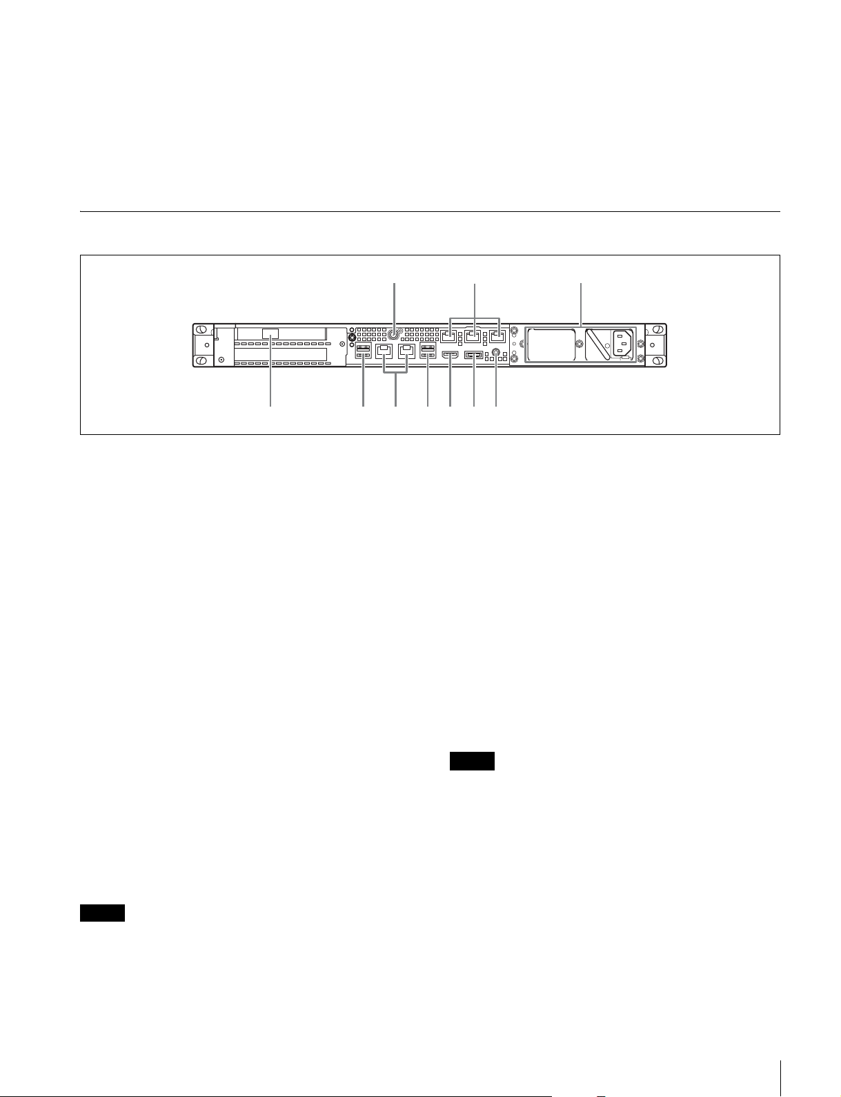
前面の USB 端子にキーボードとマウスを接続し、背面
の DisplayPort 端子または HDMI 端子にディスプレイ
を接続する。
2
本体のオン / スタンバイボタンをオンにする。
3
Windows のログイン画面が表示されたら、ユーザー名
には「cm1」パスワードには「cm1」と入力し、ログイ
ンする。
ネットワークを設定する
1
本機背面の LAN 端子に LAN ケーブルを接続し、ネット
ワークに接続する。
2
コントロールパネルの[NetworkandInternet]−
[Viewnetworkstatusandtasks]をクリックする。
3
[Connections]で LAN ケーブルを接続しているデバイ
スをクリックする。
4
[Properties]ボタンをクリックする。
5
[InternetProtocolVersion4(TCP/IPv4)]を選択して、
[Properties]ボタンをクリックする。
6
IP アドレスなどの設定を変更する。
7
DNS、WINS などの設定を行う場合は、[Advanced]
ボタンをクリックする。
8
設定が完了したら、[OK]ボタンをクリックする。
日時を設定する
1
コントロールパネルの[Clock,Language,andRegion]
で[DateandTime]−[Setthetimeanddate]を選
択する。
2
[DateandTime]タブの[Changetimezone]をク
リックして、タイムゾーンを選択する。
3
[DateandTime]タブの[Changedateandtime]を
クリックして、日付と時刻を設定する。
4
[InternetTime]タブの[Changesettings]ボタンを
クリックする。
5
NTP サーバーを設定し、[UpdateNow]ボタンをク
リックする。
6
定期的に NTP サーバーで時刻を補正する場合は、
[SynchronizewithanInternettimeserver]をチェッ
クする。
サインアウトする
設定が完了したら、Windows からサインアウトします。
1
マウスカーソルを画面の右上に移動してチャームを表
示し、[Start]をクリックする。
2
画面右上のアカウント名をクリックし、[Signout]を
クリックする。
アプリケーションの表示
本機の設定・操作は、クライアント PC からネットワーク
を介して本機に接続し、クライアント PC の Web ブラウ
ザーにアプリケーションを表示して行います。
クライアント PCの推奨環境
CPU: IntelCorei7 以上
メモリー: 4GB 以上
ストレージ: 1TB 以上
ネットワーク: ギガビット LANポート× 1
グラフィック: nVidiaQuadroFX シリーズ、NVSシリー
ズ以上
OS: Windows8.1(64 ビット版)
Windows10(64 ビット版)
Webブラウザー:
GoogleChrome
ディスプレイ: 1920 × 1080 以上
ご注意

メンテナンスアプリケーションの操作 7
上記推奨環境を備えたコンピューターを、本機背面の
LAN1 端子または LAN2 端子に接続します。コンピュー
ターの Web ブラウザーのアドレス欄に「https://(ホスト
名)/cm1/」と入力して、アプリケーションを表示させま
す。
ログイン画面が表示されたら、ユーザー名とパスワードを
入力してログインします。
工場出荷時は、下記のユーザー名とパスワードが設定され
ています。
ユーザー名 :admin
パスワード :cm1
アプリケーションの設定
アプリケーションを起動し、本システムに必要な設定を行
います。
◆ 設定方法については、アプリケーションのヘルプを参照してく
ださい。
システムの設定
Web メニューのメンテナンス画面で、本システムの設定を
行います。
◆ メンテナンス画面の操作については、「メンテナンスアプリ
ケーションの操作」(7 ページ)を参照してください。
メンテナンスアプリケー
ションの操作
システム管理者向けメンテナンスアプリケーション
(MaintenanceWebApplication)の操作については、本機
にログオンしてデスクトップ上にあるショートカットを開
いてマニュアルを参照してください。

8使用上のご注意/仕様
使用上のご注意
電源に関する注意事項
本機が動作中に突然電源が切れた場合、データが壊れる可
能性があります。データ保護のため、UPS(無停電電源装
置)のご使用をお勧めします。
また、電源コードを抜く場合やブレーカーを落とす場合は、
必ず事前に本機のオン / スタンバイボタンを押して本機の
動作を停止させてください。
USB デバイスに関する注意事項
自給電タイプの USB デバイス(ODS-D77U など)を接続し
て使用する場合、デバイスの電源がオンになるタイミング
によっては、そのデバイスを認識できない場合があります。
その場合は USB デバイスの電源を入れ直すか、USB ケー
ブルを抜いて接続し直してください。
仕様
一般
電源 AC100V 〜240V
50/60Hz
消費電力 235W
待機電力 3W 以下
使用温度 5 ℃〜35 ℃
保存温度 −20 ℃〜+60 ℃
使用湿度 20%〜90%(相対湿度)
保存湿度 5%〜80%
質量 9.7kg
外形寸法 440×43.6× 507mm(幅/高さ/奥行き)
CPU
プロセッサー IntelCorei76700TE(2.4GHz)
メモリ 8GBytes
SO-DIMM(DDR4)(2)
ドライブ(M.2) 120GBytes
ドライブ(SSD)PCIeSSD(Add-inCard)、1.2TBytes
または 2.0TBytes
本機には、下記のいずれかの PCIeSSD が接続されています。
•IntelSolid-StateDriveDCP3600(1.2TBytes)
•IntelSolid-StateDriveDCP4600(2.0TBytes)
PCIeSSDの情報については、以下のサイトをご覧ください。
•IntelSolid-StateDriveDCP3600
https://ark.intel.com/products/80990/Intel-SSD-DC-P3600-
Series-12TB-12-Height-PCIe-30-20nm-MLC
•IntelSolid-StateDriveDCP4600
https://ark.intel.com/products/96999/Intel-SSD-DC-P4600-
Series-20TB-12-Height-PCIe-31-x4-3D1-TLC
拡張バス PCIeGen28Lane(30W)(2)
単位:mm
482
440
43.6
507

仕様 9
入出力
LAN RJ-45(2)
1000BASE-T
100BASE-TX
SFP+(1)
10GBASE-SR/LR(Add-inCard)1)2)
1) 本機に接続されているネットワークカード
•IntelEthernetConvergedNetworkAdapterX520-DA1
ネットワークカードの情報については、以下のサイトを参照し
てください。
http://www.intel.com/support/go/network/adapter/
userguide.htm
2) SFP+ モジュール装着時のみ利用できます。
USB(前面 / 背面)
SuperSpeedUSB(USB3.0)TypeA
(6、うち前面 2、背面 4)
前面:給電対応(各 900 mA)
背面:右下のポートのみ給電対応
(900 mA)、他 3 ポートは給電非対応
HDMI TypeA(1)
HDMIVer.1.4a、
最大解像度 1920 × 1200、60Hz
DisplayPort DisplayPort(1)
DisplayPortVer.1.1a、
最大解像度 2560 × 1600、60Hz
別売アクセサリ
オプショナルパワーサプライPWSK-101
仕様および外観は、改良のため予告なく変更することがあ
りますが、ご了承ください。
•Windows は、米国 MicrosoftCorporation の米国およびそ
の他の国における登録商標または商標です。
•GoogleChrome は GoogleInc. の商標または登録商標です。
その他、本書に記載されているシステム名、製品名、会社
名は一般に各開発メーカーの登録商標または商標です。な
お、本文中では、®、™マークは明記していません。
本製品は、トロンフォーラム(www.tron.org)の
T-License2.1に基づき T-Kernel2.0ソースコードを利用し
ています。
使用環境によってはネットワーク上の意図せぬ第三者か
ら製品にアクセスされる可能性があります。本機をネッ
トワークに接続する際には、セキュアなネットワークで
あることをご確認の上ご使用ください。
•必ず事前に記録テストを行い、正常に記録されている
ことを確認してください。本機や記録メディア、外部
ストレージなどを使用中、万一これらの不具合により
記録されなかった場合の記録内容の補償については、
ご容赦ください。
•お使いになる前に、必ず動作確認を行ってください。
故障その他に伴う営業上の機会損失等は保証期間中お
よび保証期間経過後にかかわらず、補償はいたしかね
ますのでご了承ください。
•本製品を使用したことによるお客様、または第三者か
らのいかなる請求についても、当社は一切の責任を負
いかねます。
•本機内、記録メディア、外部のストレージ等に記録さ
れたデータの損失、修復、複製の責任は負いかねます。
•諸事情による本製品に関連するサービスの停止、中断
について、一切の責任を負いかねます。

10 Table of Contents
Table of Contents
Overview.............................................................................. 11
System Configuration and Connection ................................. 11
Supported Devices ............................................................. 11
Supported NIC ...................................................................... 11
Name and Function of Parts...............................................12
Front View ............................................................................. 12
Front View (Panel Removed)................................................. 12
Rear View............................................................................... 13
Setting Up............................................................................ 14
Initial Settings ....................................................................... 14
Displaying the Application ................................................... 14
Application Settings.............................................................. 15
System Settings ..................................................................... 15
Maintenance Web Application Operation......................... 15
Usage Precautions ............................................................. 16
Specifications ..................................................................... 16
For safety, please read the precautions described in the PWS-110 Operation
Guide (supplied).
English

11
Overview / Supported Devices
Overview
This unit is a system that manages video content stored on
a PWS-4500/BPU4800 in a 4K-Live system.
Users can build workflows using the metadata of video
content, edit the metadata from a web browser, sort video
content on multiple PWS-4500/BPU4800 units, and
transfer video content efficiently between PWS-4500/
BPU4800 units and to NAS or other external storage.
For details about operation, refer to the Help in the
application.
System Configuration and
Connection
Connect the unit to a 4K-Live system using Ethernet.
Notice to customers
Installation of the unit should be performed by your Sony
service personnel or a technician who has received service
training.
Supported Devices
Operation with the following devices has been certified.
Supported NIC
Operation with the following 10 GbE network card has
been certified.
Intel Ethernet Converged Network Adapter X520-DA1
GBGB

12 Name and Function of Parts
Name and Function of Parts
Front View
aOn/Standby button and indicator
Switches the unit on/off (standby state). Connecting the
power cord places the unit in standby state, and the
indicator turns on red. Pressing the On/Standby button
while in standby state turns on the unit and the indicator
turns on green. Pressing and holding the On/Standby
button for two seconds switches the unit to standby state,
and the indicator changes to red. To turn the unit on again
after switching from On state to standby state, when the
indicator is red, press and hold the On/Standby button for
three seconds or longer. The indicator goes out when the
power cord is disconnected.
bSYSTEM indicator
Indicates the status of the unit.
Green: Operating normally
Flashing green (once per second): System is booting or
transitioning to standby state.
Flashing orange (once per second): A warning has been
generated.
High-speed flashing read (four times per second): An
error has occurred.
cFront panel LED
Turns on according to settings in the web application. The
LED is configured using [001: LINE LED] in the
[Settings] page on the Maintenance screen.
dUSB connectors (front panel)
Connects to a keyboard and mouse for initializing the unit.
USB devices not described in this document are not supported.
• Both USB ports on the front panel support power delivery (900 mA).
• Use SuperSpeed USB cables.
Front View (Panel Removed)
When the SYSTEM indicator or web application indicates
an error, you can remove the front panel to check the status
of the hardware components.
To remove the front panel, loosen the screws on the left
and right sides and pull the panel towards you.
aFAN indicators
If any of the fans fail, the corresponding fan indicator turns
on red.
bPOWER indicators
If either of the AC power supply units fail, the
corresponding indicator turns on red.
12 3
4
Notes
123

13
Name and Function of Parts
cTEMP indicator
If an abnormally high temperature is detected within the
unit, the indicator turns on red.
Rear View
aSYSTEM TC connector
Not used by this system.
bRemote connectors (1/2, 3/4, 5)
Not used by this system.
cAC power supply units
Insert the power cords and connect to power outlets.
Only one AC power supply unit is installed at the factory.
A second optional power supply unit can be installed to
provide power supply redundancy. When used in systems
that require reliability, power supply redundancy allows
the unit to continue operating even if a power supply unit
fails.
For details about installing or replacing a power supply
unit, consult your Sony sales or service representative.
dSFP+ slot
Attach to an SFP+ module.
eUSB connectors (rear panel)
Connect to drive units using USB cables.
USB devices not described in this document are not
supported.
• Of the four USB connectors on the rear panel, only the bottom right port
supports power delivery (900 mA). The other three ports do not support
power delivery, and should be used to connect USB devices that do not
require power supplied from the USB connector.
• Use SuperSpeed USB cables.
fLAN connectors
Connect to a Gigabit Ethernet network.
gHDMI connector
Connect to a monitor using an HDMI cable.
Use an HDMI cable that conforms to the following
standard.
• High Speed HDMI Cable (Premium High Speed HDMI
Cable)
hDisplayPort connector
Connect to a monitor using a DisplayPort-to-DVI
converter cable or DisplayPort-to-HDMI converter cable.
Use an active-type converter cable.
Use a DisplayPort cable that conforms to the following standard.
• DP v1.2a (compliant)
iGround terminal
Connect to ground.
LAN1 LAN2
112 3
6768945
Notes
Note

14 Setting Up
Setting Up
Initial Settings
Before using the unit, configure the Windows settings
within the unit. The description below describes the
standard settings in Windows 8.
To reboot the unit, first shut down the unit and then turn the On/Standby
button on the front panel on again, without rebooting Windows.
1
Connect a keyboard and mouse to the USB connectors
on the front panel, and connect a monitor to the
DisplayPort connector or HDMI connector on the rear
panel.
2
Turn the On/Standby button on.
3
When the Windows login screen appears, enter “cm1”
as the user name and “cm1” as the password, and log
in.
Configuring the network
1
Connect a LAN cable to the LAN connector on the rear
panel of the unit, and connect the other end to the
network.
2
Click [View network status and tasks] under [Network
and Internet] in the control panel.
3
Click the device connected by LAN cable in
[Connections].
4
Click the [Properties] button.
5
Select [Internet Protocol Version 4 (TCP/IPv4)], then
click the [Properties] button.
6
Change the IP address and other settings.
7
Click the [Advanced] button to configure DNS,
WINS, and other settings.
8
When finished, click the [OK] button.
Setting the date and time
1
Select [Set the time and date] under [Date and Time]
in the [Clock, Language, and Region] control panel.
2
Click [Change time zone] on the [Date and Time] tab,
and select the time zone.
3
Click [Change date and time] on the [Date and Time]
tab, and set the date and time.
4
Click the [Change settings] button on the [Internet
Time] tab.
5
Specify an NTP server, then click the [Update Now]
button.
6
Place a check mark in [Synchronize with an Internet
time server] to periodically correct the clock using the
NTP server.
Signing out
When finished, sign out from Windows.
1
Move the mouse cursor to the top right corner of the
screen to display the Charms bar, then click [Start].
2
Click the account name on the top right of the screen,
then click [Sign out].
Displaying the Application
Connect a client PC to the unit via the network to display
the application in a web browser on the client PC in order
to configure and control the unit.
Recommended client PC environment
CPU: Intel Core i7 or higher
Memory: 4 GB or higher
Storage: 1 TB or higher
Network: Gigabit LAN port (1)
Graphics: nVidia Quadro FX series, NVS series or
higher
OS: Windows 8.1 (64-bit version)
Windows 10 (64-bit version)
Web browser: Google Chrome
Display resolution:
1920 × 1080 pixels or higher
Connect a computer satisfying the recommended
conditions above to the LAN1 or LAN2 connector on the
rear panel of the unit. Enter “https://(host_name)/cm1/” in
the address bar of a web browser on the computer to
display the application.
Enter the user name and password when the login screen
appears.
The following user name and password are configured by
default.
Note

15
Maintenance Web Application Operation
User name: admin
Password: cm1
Application Settings
Launch the application and configure the required system
settings.
For details about configuration, refer to the Help in the
application.
System Settings
Configure the system settings on the Maintenance screen
in the web application.
For details about the Maintenance screen, see
“Maintenance Web Application Operation” on page 15.
Maintenance Web
Application Operation
For details about the operation of the Maintenance Web
Application for system administrators, log in to the unit
and click the shortcut icon on the desktop to refer to the
Operation Manual.

16 Usage Precautions / Specifications
Usage Precautions
Power supply precautions
If the unit is suddenly turned off during operation, data loss
may occur. To maintain data integrity, the use of an
uninterruptible power supply (UPS) is recommended.
To disconnect the power cord or turn off the breaker,
always press the On/Standby button on the unit to stop the
unit before proceeding.
USB device precautions
When using the unit when connected to a self-powered
USB device (such as the ODS-D77U), the device may not
be recognized, depending on the timing of when the device
is turned on. If this occurs, turn the USB device off and on
again, or disconnect and reconnect the USB cable.
Specifications
General
Power requirement
100 V to 240 V AC
50/60 Hz
Power consumption
235 W
Standby power consumption
3Worlower
Operating temperature
5°C to 35 °C (41 °F to 95 °F)
Storage temperature
–20 °C to +60 °C (−4°F to +140 °F)
Operating humidity
20% to 90% (relative humidity)
Storage humidity
5% to 80%
Mass 9.7 kg (21 lb. 6.2 oz.)
Dimensions 440 ×43.6 ×507 mm (17 3/8×1 3/4×
20 in.) (width / height / depth)
CPU
Processor Intel Core i7 6700TE (2.4 GHz)
Memory 8 GBytes
SO-DIMM (DDR4) (2)
Drive (M.2) 120 GBytes
Drives (SSD) PCIe SSD (Add-in Card), 1.2 TBytes or
2.0 TBytes
One of the following PCIe SSDs is connected to the unit.
•Intel Solid-State Drive DC P3600 (1.2 TBytes)
•Intel Solid-State Drive DC P4600 (2.0 TBytes)
For details about PCIe SSDs, visit the following sites.
•Intel Solid-State Drive DC P3600
https://ark.intel.com/products/80990/Intel-SSD-DC-P3600-Series-
1_2TB-12-Height-PCIe-3_0-20nm-MLC
•Intel Solid-State Drive DC P4600
https://ark.intel.com/products/96999/Intel-SSD-DC-P4600-Series-
2_0TB-12-Height-PCIe-3_1-x4-3D1-TLC
Units: mm (in.)
440 (17 3/8)
482 (19)
43.6 (1 3/4)
507 (20)

17
Specifications
Expansion bus PCIe Gen2 8Lane (30 W) (2)
Inputs/outputs
LAN RJ-45 (2)
1000BASE-T
100BASE-TX
SFP+ (1)
10GBASE-SR/LR (Add-in Card)1)2)
1) Network card connected to the unit
•Intel Ethernet Converged Network Adapter X520-DA1
For information about the network card, visit the following site.
http://www.intel.com/support/go/network/adapter/userguide.htm
2) Supported only when SFP+ module is attached.
USB (front panel/rear panel)
Super Speed USB (USB 3.0) Type A
(6, 2 on front and 4 on rear)
Front: Power delivery support (900 mA/
port)
Rear: Power delivery support on bottom
right port (900 mA), not supported on
other three ports
HDMI Type A (1)
HDMI Ver. 1.4a,
1920 ×1200 maximum resolution,
60 Hz
DisplayPort DisplayPort (1)
DisplayPort Ver. 1.1a,
2560 ×1600 maximum resolution,
60 Hz
Optional accessories
PWSK-101 Optional Power Supply
Design and specifications are subject to change without
notice.
• Windows is a registered trademark of Microsoft
Corporation in the United States and other countries.
• Google Chrome is a trademark or registered trademark
of Google Inc.
Other products or system names appearing in this
document are trademarks or registered trademarks of their
respective owners. Further, the ®, or ™symbols are not
used in the text.
This Product uses the Source Code of T-Kernel 2.0 under
T-License 2.1 granted by TRON Forum (www.tron.org).
Depending on the operating environment, unauthorized
third parties on the network may be able to access the
unit. When connecting the unit to the network, be sure to
confirm that the network is protected securely.
Notes
• Always make a test recording, and verify that it was
recorded successfully.
SONY WILL NOT BE LIABLE FOR DAMAGES OF
ANY KIND INCLUDING, BUT NOT LIMITED TO,
COMPENSATION OR REIMBURSEMENT ON
ACCOUNT OF FAILURE OF THIS UNIT OR ITS
RECORDING MEDIA, EXTERNAL STORAGE
SYSTEMS OR ANY OTHER MEDIA OR
STORAGE SYSTEMS TO RECORD CONTENT OF
ANY TYPE.
• Always verify that the unit is operating properly before
use. SONY WILL NOT BE LIABLE FOR
DAMAGES OF ANY KIND INCLUDING, BUT
NOT LIMITED TO, COMPENSATION OR
REIMBURSEMENT ON ACCOUNT OF THE LOSS
OF PRESENT OR PROSPECTIVE PROFITS DUE
TO FAILURE OF THIS UNIT, EITHER DURING
THE WARRANTY PERIOD OR AFTER
EXPIRATION OF THE WARRANTY, OR FOR
ANY OTHER REASON WHATSOEVER.
• SONY WILL NOT BE LIABLE FOR CLAIMS OF
ANY KIND MADE BY USERS OF THIS UNIT OR
MADE BY THIRD PARTIES.
• SONY WILL NOT BE LIABLE FOR THE LOSS,
REPAIR, OR REPRODUCTION OF ANY DATA
RECORDED ON THE INTERNAL STORAGE
SYSTEM, RECORDING MEDIA, EXTERNAL
STORAGE SYSTEMS OR ANY OTHER MEDIA
OR STORAGE SYSTEMS.
• SONY WILL NOT BE LIABLE FOR THE
TERMINATION OR DISCONTINUATION OF ANY
SERVICES RELATED TO THIS UNIT THAT MAY
RESULT DUE TO CIRCUMSTANCES OF ANY
KIND.

18 Specifications
For the customers in Taiwan

19
Table des matières
Table des matières
Présentation........................................................................ 20
Configuration système et connexion ..................................... 20
Périphériques pris en charge............................................ 20
NIC pris en charge................................................................. 20
Nomenclature ...................................................................... 21
Vue de face............................................................................. 21
Vue de face (Panneau retiré) .................................................. 21
Vue arrière.............................................................................. 22
Mise en service................................................................... 23
Réglages initiaux ................................................................... 23
Affichage de l’application ..................................................... 23
Réglages de l’application ...................................................... 24
Réglages système .................................................................. 24
Fonctionnement de l’application Maintenance Web....... 24
Précautions d’utilisation.................................................... 25
Spécifications..................................................................... 25
Afin de garantir votre sécurité, veuillez lire les précautions décrites dans le
guide d’utilisation du PWS-110 (fourni).
Français
GBFR

20 Présentation / Périphériques pris en charge
Présentation
Cet appareil est un système qui gère les contenus vidéo
stockés sur le PWS-4500/BPU4800 dans un système 4K-
Live.
Les utilisateurs peuvent créer leurs propres workflows en
utilisant les métadonnées du contenu vidéo, monter les
métadonnées à partir d’un navigateur Web, trier des
contenus vidéo sur plusieurs appareils PWS-4500/
BPU4800, et transférer efficacement des contenus vidéo
entre les appareils PWS-4500/BPU4800 et vers un NAS ou
un autre périphérique de stockage externe.
Pour plus de détails sur le fonctionnement, consultez
l’aide de l’application.
Configuration système et connexion
Connectez l’appareil au système 4K-Live à l’aide
d’Ethernet.
Avis à l’intention des clients
L’installation de l’appareil doit être réalisée par un
membre du personnel de service après-vente Sony ou un
technicien qui a suivi une formation.
Périphériques pris en
charge
L’utilisation des périphériques suivants a été certifiée.
NIC pris en charge
Le fonctionnement avec la carte réseau 10 GbE suivante a
été certifié.
Adaptateur de réseau converge Intel Ethernet X520-DA1
Table of contents
Languages:
Other Sony Control System manuals
Popular Control System manuals by other brands

BADU
BADU JET Wireless Control II translation of original operation manual

Bend-Tech
Bend-Tech Dragon A400 Maintenance & troubleshooting

B&B ARMR
B&B ARMR 730 Series Operation & maintenance manual

DriSteem
DriSteem Vapor-logic3 Installation and operation manual

Nuvation Energy
Nuvation Energy NUVG5 product manual

Mitsubishi Electric
Mitsubishi Electric AE-200A Instruction book

Pilz
Pilz PSS u2 ES 16DI operating manual

igus
igus motion Plastics D8-1 manual

Salus
Salus ZigBee CO10RF installation manual

Zodiac
Zodiac iAqualink IQ904-P quick start guide

SoundOFF
SoundOFF bluePRINT ENGND20001 quick start guide

Motorline professional
Motorline professional SIGMA 4M User& installer's manual