– 3 –
TABLE OF CONTENTS
Section Title Page Section Title Page
Service Note ............................................................................ 4
1. GENERAL
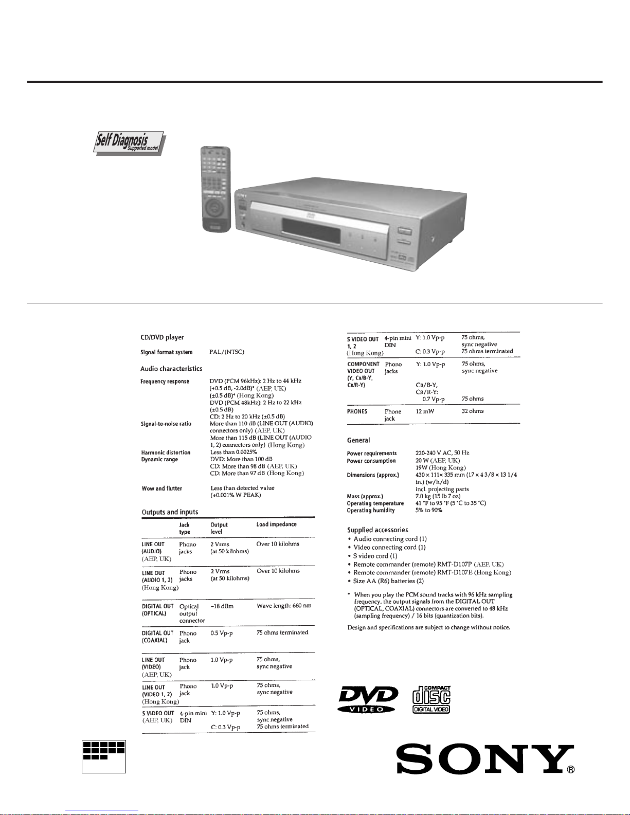
This Player Can Play the Following Discs .................... 1-1
Getting Started .............................................................. 1-1
Basic Operations ........................................................... 1-2
Playing Discs in Various Modes.................................... 1-4
Setting and Adjustments ............................................... 1-9
Additional Information ................................................... 1-10
2. DISASSEMBLY
2-1. Upper Case Removal.................................................... 2-1
2-2. Front Panel Removal .................................................... 2-1
2-3. Door Open/Close Motor Removal................................. 2-1
2-4. MB-84 Board Removal.................................................. 2-1
2-5. AU-218 Board Removal ................................................ 2-2
2-6. MD Block Ass’y Removal .............................................. 2-2
2-7. TK-47 Board Removal................................................... 2-2
2-8. Tray Removal ................................................................ 2-2
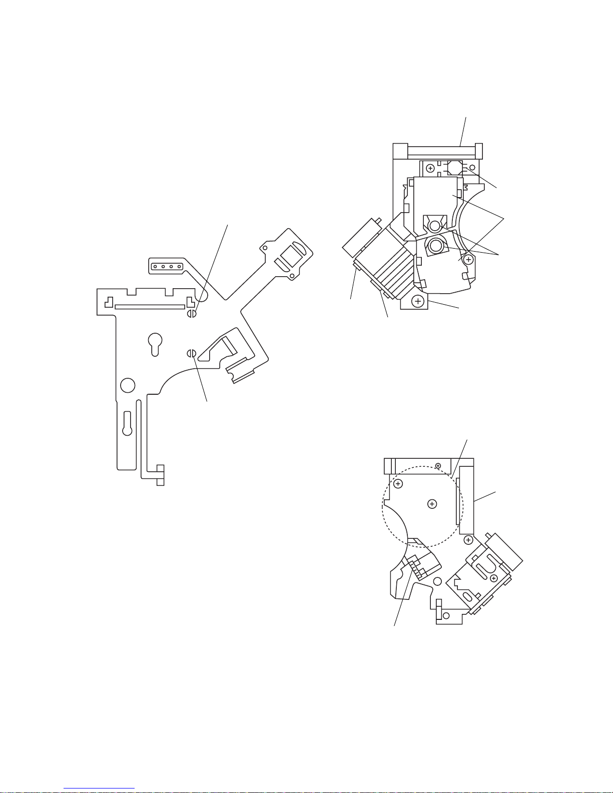
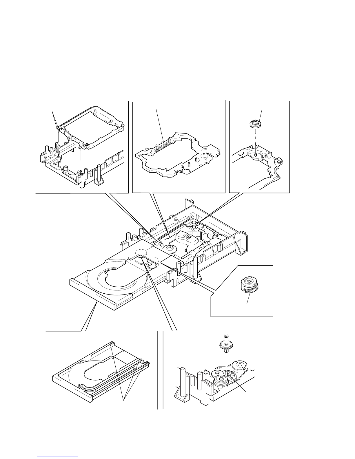
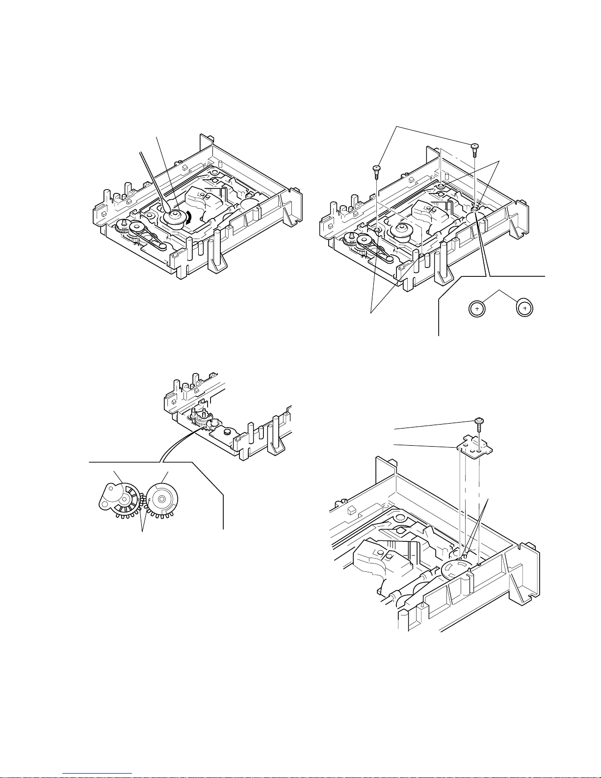
2-9. Skew Motor (M903) Removal ....................................... 2-3
2-10. Sled Motor (M501) Removal ......................................... 2-3
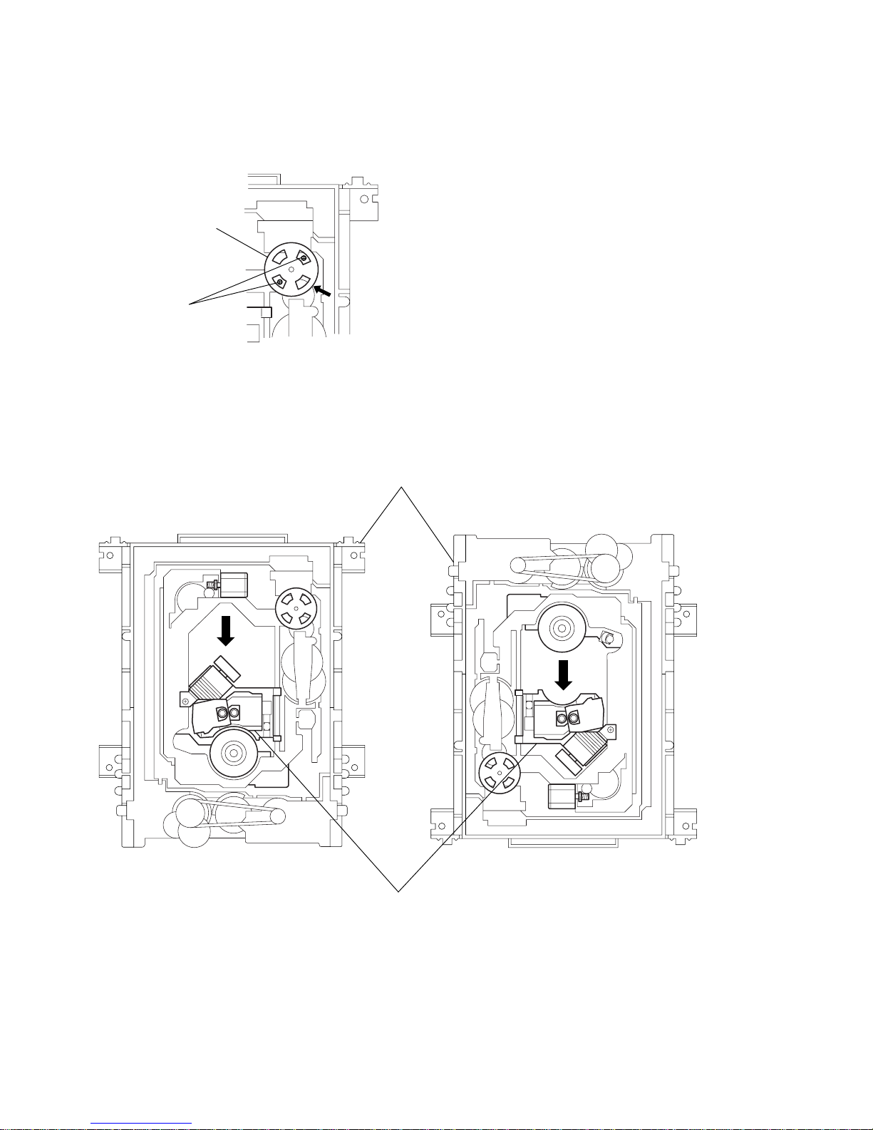
2-11. Spindle Motor (M901) Removal .................................... 2-3
2-12. Optical Pick-up Removal............................................... 2-3
2-13. Internal Views ................................................................ 2-4
2-14. Circuit Boards Location ................................................. 2-5
3. BLOCK DIAGRAMS
3-1. Overall Block Diagram .................................................. 3-1
3-2. RF/Servo Block Diagram .............................................. 3-3
3-3. Signal Process Block Diagram ..................................... 3-5
3-4. Video Block Diagram..................................................... 3-7
3-5. System Control Block Diagram ..................................... 3-9
3-6. Audio Block Diagram..................................................... 3-11
3-7. Mode Control Block Diagram ........................................ 3-13
3-8. Power Block Diagram.................................................... 3-15
4. PRINTED WIRING BOARDS AND SCHEMATIC
DIAGRAMS
4-1. Frame Schematic Diagram ........................................... 4-3
4-2. Printed Wiring Boards and Schematic Diagrams ......... 4-7
TK-47 Printed Wiring Board .......................................... 4-7
TK-47 (RF, Servo 1) Schematic Diagram ..................... 4-11
TK-47 (RF, Servo 2) Schematic Diagram ..................... 4-13
MB-84, FG-43 Printed Wiring Boards........................... 4-15
MB-84 (AV Decoder) Schematic Diagram .................... 4-19
MB-84 (Clock Generator) Schematic Diagram............. 4-21
MB-84 (DNR) Schematic Diagram................................ 4-23
MB-84 (Video Encoder) Schematic Diagram................ 4-25
MB-84 (Drive 1) Schematic Diagram ............................ 4-27
MB-84 (Drive 2), FG-43 Schematic Diagrams.............. 4-29
MB-84 (DSP 1) Schematic Diagram ............................. 4-31
MB-84 (DSP 2) Schematic Diagram ............................. 4-33
MB-84 (Bias) Schematic Diagram ................................ 4-35
MB-84 (IF µ-com) Schematic Diagram ......................... 4-37
MB-84 (L Gate Array) Schematic Diagram ................... 4-39
MB-84 (ARP, Decrypt) Schematic Diagram.................. 4-41
MB-84 (System µ-com) Schematic Diagram ................ 4-43
MB-84 (S Gate Array) Schematic Diagram .................. 4-45
AU-218 Printed Wiring Board ....................................... 4-47
AU-218 (Audio 1) Schematic Diagram ......................... 4-51
AU-218 (Audio 2) Schematic Diagram ......................... 4-53
AU-218 (Video Buffer) Schematic Diagram.................. 4-55
YS-19 Printed Wiring Board and
Schematic Diagram ....................................................... 4-57
ER-8 Printed Wiring Board............................................ 4-59
ER-8 (EURO AV 1) Schematic Diagram ....................... 4-63
ER-8 (EURO AV 2) Schematic Diagram ....................... 4-65
ER-8 (EURO AV 3) Schematic Diagram ....................... 4-67
HP-120 Printed Wiring Board and
Schematic Diagram ....................................................... 4-69
FP-75 Printed Wiring Board .......................................... 4-71
FP-75 Schematic Diagram............................................ 4-73
CN-113, DR-88, FL-108, FR-160, PW-120
Printed Wiring Boards ................................................... 4-75
CN-113, DR-88, FL-108, FR-160, PW-120
Schematic Diagrams ..................................................... 4-77
PS-421 Printed Wiring Board........................................ 4-79
PS-421 Schematic Diagram.......................................... 4-81
POWER BLOCK (HS-930SH) Printed Wiring Board.... 4-83
POWER BLOCK (HS-930SH) Schematic Diagram...... 4-85
5. IC PIN FUNCTION DESCRIPTION
5-1. Interface Control Pin Function (MB-84 Board IC604) .. 5-1
5-2 System Control Pin Function (MB-84 Board IC805) .... 5-2
6. TEST MODE
6-1. Starting up Test Mode ................................................... 6-1
6-2. Selection of Check Item ................................................ 6-1
6-2-1. Selected Item Check ................................................ 6-1
6-2-2. All Items Check ........................................................ 6-1
6-3. Error Display.................................................................. 6-2
6-4. General Description of Checking Method..................... 6-2
6-5. Drive Auto Adjustment .................................................. 6-8
6-6. Drive Manual Operation ................................................ 6-12
6-6-1. Drive Manual Operation Menu Screen .................... 6-12
6-6-2. Disc Type .................................................................. 6-12
6-6-3. Manual Control 1...................................................... 6-12
6-6-4. Manual Control 2...................................................... 6-13
6-6-5. Manual Control 3...................................................... 6-13
6-6-6. Manual Adjust 1 ....................................................... 6-13
6-6-7. Manual Adjust 2 ....................................................... 6-14
6-6-8. Auto Adjust ............................................................... 6-14
6-6-9. Check ....................................................................... 6-14
6-6-10. EEPROM Data Screen Display................................ 6-15
6-7. Other Operation............................................................. 6-15
6-8. Emergency History........................................................ 6-16
6-9. Error Code ..................................................................... 6-18
7. ELECTRICAL ADJUSTMENT
7-1. Power Supply Check ..................................................... 7-1
1. HS-930SH Board........................................................... 7-1
7-2. Adjustment of System Control ...................................... 7-2
1. System Clock 27 MHz Adjustment................................ 7-2
7-3. Adjustment of Video System......................................... 7-2
1. Video Level Adjustment ................................................ 7-2
2. S-terminal Output Check............................................... 7-2
3. Checking Component Video Output B-Y ...................... 7-2
4. Checking Component Video Output R-Y ...................... 7-3
5. Checking Component Video Output Y.......................... 7-3
6. Checking RGB Output R ............................................... 7-3
7. Checking RGB Output G............................................... 7-3
8. Checking RGB Output B ............................................... 7-4
9. Checking S Video Output S-C ...................................... 7-4
10. Checking S Video Output DC Level.............................. 7-4
7-4. Adjustment Related Parts Arrangement ....................... 7-6
8. REPAIR PARTS LIST
8-1. Exploded Views ............................................................. 8-1
8-1-1. Case Assembly ........................................................ 8-1
8-1-2. Front Panel Assembly .............................................. 8-2
8-1-3. Chassis Assembly .................................................... 8-3
8-1-4. DVD Mechanism Chassis Assembly (1) .................. 8-5
8-1-5. DVD Mechanism Chassis Assembly (2) .................. 8-6
8-2. Electrical Parts List........................................................ 8-7