Sony RDR-GX300 User manual

SERVICE MANUAL
DVD RECORDER
SPECIFICATIONS
RDR-GX300
RMT-D205A
US Model
Canadian Model
System
Laser: Semiconductor laser
Channel coverage:
NTSC
VHF: 2 to 13/UHF: 14 to 69/CATV: A-8 to
A-1, A to W, W+1 to W+84
Video reception: Frequency synthesizer
system
Audio reception: Split carrier system
Antenna: 75-ohm antenna terminal for VHF/
UHF
Timer:Clock:Quartzlocked/Timerindication:
12-hour cycle (digital)/Power back-up
duration: 1 hour
Video recording format: MPEG Video
Audio recording format/applicable bit rate:
Dolby Digital/2 ch, 256 kbps
When you play PCM sound tracks with a 96 kHz
sampling frequency, the output signals from the
DIGITAL OUT (OPTICAL or COAXIAL) jack
are converted to 48 kHz sampling frequency.
Inputs
(Jack name: Jack type/input level/input
impedance)
LINE IN 1/2/3
(AUDIO): Phono jack/2 Vrms/more than 22
kilohms
(VIDEO): Phono jack/1.0 Vp-p
(S VIDEO): 4-pin mini DIN/Y:1.0 Vp-p, C:
0.286 Vp-p
Outputs
(Jack name: Jack type/output level/output
impedance)
LINE OUT 1/2
(AUDIO): Phono jack/2 Vrms/10 kilohms
(VIDEO): Phono jack/1.0 Vp-p
(S VIDEO): 4-pin mini DIN/Y:1.0 Vp-p, C:
0.286 Vp-p
DIGITAL OUT (OPTICAL):
Opticaloutputjack/–18dBm (wavelength:
660 nm)
DIGITAL OUT (COAXIAL):
Phono jack/0.5 Vp-p/75 ohms
COMPONENT VIDEO OUT (Y, PB, PR):
Phono jack/Y: 1.0 Vp-p/PB, PR:
interlace*=0.648 Vp-p, progressive or
interlace**=0.7 Vp-p
* “Y/Pb/Pr Out Black Level” is “On”
** “Y/Pb/Pr Out Black Level” is “Off”
SET TOP BOX CONTROL:
Mini jack
General
Power requirements: 120 V AC, 60 Hz
Power consumption: 37 W
Dimensions (approx.): 430 ×85 ×345 mm
(17×3 3/
8
×13 5/
8
in.) (width/height/depth)
incl. projecting parts
Mass (approx.): 4.8 kg (10.58 lb)
Operating temperature: 5 ºC to 35 ºC
(41 ºF to 95 ºF)
Operating humidity: 25 % to 80 %
Supplied accessories:
Audio/video cord (1)
Power cord (1)
Antenna cable (1)
Set top box controller (1)
Remote commander (remote) (1)
Size AA(R6) batteries (2)
Specifications and design are subject to change
without notice.
All manuals and user guides at all-guides.com
all-guides.com

— 2 —
SAFETY-RELATED COMPONENT WARNING!!
COMPONENTS IDENTIFIED BY MARK 0OR DOTTED LINEWITH
MARK 0ON THE SCHEMATIC DIAGRAMS AND IN THE PARTS
LIST ARE CRITICAL TO SAFE OPERATION. REPLACE THESE
COMPONENTS WITH SONY PARTS WHOSE PART NUMBERS
APPEAR AS SHOWN IN THIS MANUAL OR IN SUPPLEMENTS
PUBLISHED BY SONY.
1. Check the area of yourrepair for unsoldered or poorly-soldered
connections. Checkthe entire board surface for solder splashes
and bridges.
2. Check the interboard wiring to ensure that no wires are
"pinched" or contact high-wattage resistors.
3. Look for unauthorized replacement parts, particularly
transistors, that were installed during a previous repair. Point
them out to the customer and recommend their replacement.
4. Look for parts which, through functioning, show obvious signs
of deterioration. Point them out to the customer and
recommend their replacement.
5. Check the B+ voltage to see it is at the values specified.
6. Flexible Circuit Board Repairing
•Keep the temperature of the soldering iron around 270˚C
during repairing.
•Do not touch the soldering iron on the same conductor of the
circuit board (within 3 times).
•Be careful not to apply force on the conductor when soldering
or unsoldering.
SAFETY CHECK-OUT
After correcting the original service problem, perform the following
safety checks before releasing the set to the customer.
CAUTION
Use of controls or adjustments or performance of procedures
otherthanthose specifiedherein may result inhazardousradiation
exposure.
WARNING!!
WHEN SERVICING, DO NOT APPROACHTHE LASER EXIT WITH
THE EYE TOO CLOSELY. IN CASE IT IS NECESSARY TO
CONFIRM LASER BEAM EMISSION, BE SURE TO OBSERVE
FROM A DISTANCE OF MORE THAN 25 cm FROMTHE SURFACE
OF THE OBJECTIVE LENS ON THE OPTICAL PICK-UP BLOCK.
CAUTION:
The use of optical instrument with this product will increase eye
hazard.
Unleaded solder
Boards requiring use of unleaded solder are printed with the lead-
free mark (LF) indicating the solder contains no lead.
(Caution: Some printed circuit boards may not come printed with
the lead free mark due to their particular size.)
: LEAD FREE MARK
Unleaded solder has the following characteristics.
•Unleaded solder melts at a temperature about 40°C higher than
ordinary solder.
Ordinary soldering irons can be used but the iron tip has to be
applied to the solder joint for a slightly longer time.
Soldering irons using a temperature regulator should be set to
about 350°C.
Caution: The printed pattern (copper foil) may peel away if the
heated tip is applied for too long, so be careful!
•Strong viscosity
Unleaded solder is more viscous (sticky, less prone to flow) than
ordinary solder so use caution not to let solder bridges occur such
as on IC pins, etc.
•Usable with ordinary solder
It is best to use only unleaded solder but unleaded solder may
also be added to ordinary solder.
All manuals and user guides at all-guides.com

—3 —
TABLE OF CONTENTS
SERVICE NOTE
1. DISK REMOVAL PROCEDURE IF THE TRAY
CANNOT BE EJECTED (FORCED EJECTION) ············ 5
1. GENERAL
WARNING ············································································1-1
Precautions·············································································1-1
Ways to UseYour DVD Recorder··········································1-1
Quick Guide to Disc Types ····················································1-2
Hookups and Settings ································································1-3
Hooking Up the Recorder ······················································1-3
Step 1: Unpacking ·································································1-3
Step 2: Connecting the Antenna Cable and Set Top Box
Controller ···············································································1-3
Step 3: Connecting the Video Cords ······································1-4
Step 4: Connecting the Audio Cords ·····································1-4
Step 5: Connecting the Power Cord·······································1-5
Step 6: Preparing the Remote ················································1-5
Step 7: Easy Setup ·································································1-5
Setting Up the VCR Plus ®System ······································1-6
Connecting a VCR or Similar Device····································1-7
Guide to Displays ······································································1-7
Using the On-Screen Menus ··················································1-7
Using the Title List ································································1-8
Using the “Disc Info”Screen (disc settings) ·························1-8
Checking the Play Information and Playing Time·················1-9
How to Enter Characters························································1-9
Recording ················································································1-10
Before Recording·································································1-10
Timer Recording (Standard/VCR Plus+)·····························1-10
Checking/Changing/Canceling Timer Settings (Timer List)···
1-11
Recording Without the Timer ··············································1-11
Recording From a VCR or Similar Device ··························1-12
Playback ··················································································1-12
Playing ·················································································1-12
Chasing Playback/Simultaneous Rec and Play····················1-14
Searching for a Title/Chapter/Track, etc.·····························1-14
Playing MP3 Audio Tracks ··················································1-14
Editing ·····················································································1-15
Before Editing······································································1-15
Editing a Title ······································································1-15
Creating and Editing a Playlist ············································1-16
Settings and Adjustments ························································1-17
Using the Setup Displays·····················································1-17
Antenna Reception and Language Settings (Settings)·········1-17
Video Settings (Video)·························································1-18
Audio Settings (Audio)························································1-19
Recording and Parental Control Settings (Features) ···········1-19
Disc and Remote Control Settings/Factory Settings
(Options) ··············································································1-20
Easy Setup (Resetting the Recorder) ···································1-20
Additional Information ····························································1-20
Troubleshooting ···································································1-20
Self-diagnosis Function (When letters/numbers appear in the
display) ················································································1-21
Notes About This Recorder ·················································1-21
Specifications·······································································1-22
Guide to Parts and Controls ·················································1-22
Glossary ···············································································1-23
Language Code List ·····························································1-23
Cable Box/Satellite Receiver Brand Code···························1-24
2. DISASSEMBLY
2-1. UPPER CASE ·································································2-2
2-2. RD-50 BOARD ·······························································2-3
2-3. D.C. FAN·········································································2-4
2-4. POWER BLOCK·····························································2-4
2-5. TRAY COVER ASSEMBLY ··········································2-5
2-6. DVD DRIVE ···································································2-6
2-7. FRONT PANEL SECTION·············································2-7
2-8. DOOR··············································································2-7
2-9. FR-216 BOARD, FL-141 BOARD ·································2-8
2-10. REAR PANEL ·································································2-8
2-11. AV-84 BOARD ································································2-9
2-12. CIRCUIT BOARDS LOCATION ·································2-10
3. BLOCK DIAGRAMS
3-1. OVERALL BLOCK DIAGRAM (1/2) ···························3-1
3-2. OVERALL BLOCK DIAGRAM (2/2) ···························3-3
3-3. POWER BLOCK DIAGRAM (1/3) ································3-5
3-4. POWER BLOCK DIAGRAM (2/3) ································3-7
3-5. POWER BLOCK DIAGRAM (3/3) ································3-9
4. SCHEMATIC DIAGRAMS
4-1. FRAME SCHEMATIC DIAGRAM································4-1
4-2. SCHEMATIC DIAGRAMS ············································4-3
WAVEFORMS ································································4-4
•AV-84 (1/8) (POWER)
SCHEMATIC DIAGRAM ······························4-7
•AV-84 (2/8) (AUDIO IN)
SCHEMATIC DIAGRAM ······························4-9
•AV-84 (3/8) (AUDIO OUT)
SCHEMATIC DIAGRAM ····························4-11
•AV-84 (4/8) (TUNER)
SCHEMATIC DIAGRAM ····························4-13
•AV-84 (5/8) (SYSTEM CONTROL)
SCHEMATIC DIAGRAM ····························4-15
•AV-84 (6/8) (VIDEO IN)
SCHEMATIC DIAGRAM ····························4-17
•AV-84 (7/8) (VIDEO OUT)
SCHEMATIC DIAGRAM ····························4-19
•AV-84 (8/8) (STB CONTROL)
SCHEMATIC DIAGRAM ····························4-21
•CN-220 (RELAY)
SCHEMATIC DIAGRAM ····························4-23
•FL-141 (DV/LINE 2 IN/FL DRIVER)
SCHEMATIC DIAGRAM ····························4-25
•FR-216 (LED DRIVE, FUNCTION KEY)
SCHEMATIC DIAGRAM ····························4-27
•RD-50 (1/19) (CONNECTOR)
SCHEMATIC DIAGRAM ····························4-29
•RD-50 (2/19) (VIDEO DECODER)
SCHEMATIC DIAGRAM ····························4-31
•RD-50 (3/19) (AV GLUE)
SCHEMATIC DIAGRAM ····························4-33
•RD-50 (4/19) (AV ENCODER)
SCHEMATIC DIAGRAM ····························4-35
•RD-50 (5/19) (MR PROCESS)
SCHEMATIC DIAGRAM ····························4-37
•RD-50 (6/19) (AV DECODER)
SCHEMATIC DIAGRAM ····························4-39
•RD-50 (7/19) (SDRAM)
SCHEMATIC DIAGRAM ····························4-41
•RD-50 (8/19) (NAZCA)
SCHEMATIC DIAGRAM ····························4-43
•RD-50 (9/19) (SDRAM)
SCHEMATIC DIAGRAM ····························4-45
•RD-50 (10/19) (AUDY, DAC)
SCHEMATIC DIAGRAM ····························4-47
•RD-50 (11/19) (JTAG)
SCHEMATIC DIAGRAM ····························4-49
•RD-50 (12/19) (SH)
SCHEMATIC DIAGRAM ····························4-51
All manuals and user guides at all-guides.com

—4 —
•RD-50 (13/19) (SDRAM, NAND FLASH)
SCHEMATIC DIAGRAM ····························4-53
•RD-50 (14/19) (SWA/UNSW BUFFER-1)
SCHEMATIC DIAGRAM ····························4-55
•RD-50 (15/19) (SWA/UNSW BUFFER-2)
SCHEMATIC DIAGRAM ····························4-57
•RD-50 (16/19) (FLASH ROM)
SCHEMATIC DIAGRAM ····························4-59
•RD-50 (17/19) (GPS3 (HOST GLUE))
SCHEMATIC DIAGRAM ····························4-61
•RD-50 (18/19) (PLL)
SCHEMATIC DIAGRAM ····························4-63
•RD-50 (19/19) (POWER)
SCHEMATIC DIAGRAM ····························4-65
5. IC PIN FUNCTION DESCRIPTION
5-1. IT CONTROL IC (IC603: N603H2MC-511FPUO (AV-84
BOARD)) ········································································5-1
6. SERVICE MODE
6-1. Checking Item ·································································6-1
6-2. Screen Transition in the Service Mode····························6-2
6-3. Service Mode Menu Items and Description ····················6-3
6-4. Device Check Menu (1/2) ···············································6-3
6-5. Device Check Menu (2/2) ···············································6-3
6-6. Path Check Menu (1/2)····················································6-4
6-7. Path Check Menu (2/2)····················································6-4
6-8. Hard Disk Check Menu ···················································6-4
6-9. Device AUTO Check Screen Transition ··························6-5
6-10. Device Individual Check, Screen Transition ···················6-5
6-11. Path Individual Check (Pasted Screen Check (visual check)
and data check (digital video data auto-check) )
Screen Transition ·····························································6-6
6-12. Path Individual Check (Audio output Confirmation)
Screen Transition ·····························································6-6
7. ADJUSTMENT
1. Videl LevlAdjustment (RD-046 Board) ·························7-1
2. Component Video Output Level Adjustment ··················7-1
3. S-Video Output S-Y Check ·············································7-1
4. S-Video Output S-C Level Check ···································7-2
5. Component Video Output Y Check ·································7-2
6. Component Video Output B-Y Chec ·······························7-2
7. Component Video Output R-Y Check ·····························7-2
8. REPAIR PARTS LIST
8-1. EXPLODED VIEWS
8-1-1.OVERALL SECTION·····················································8-1
8-1-2.DVD DRIVE ···································································8-2
8-1-3.CHASSIS BLOCK ··························································8-3
8-2. ELECTRICAL PARTS LIST ··········································8-4
All manuals and user guides at all-guides.com

—5 —
SERVICE NOTE
1. DISK REMOVAL PROCEDURE IF THE TRAY CANNOT BE EJECTED (FORCED EJECTION)
1. Remove the upper case.
2. Remove the RD-50 board, RD bracket.
3. Insert the stiff wire in the hole and eject the tray.
NOTES DURING THE FORCED EJECTION
1. If the forced ejection is executed while a blank disc media (DVD±RW, ±R) exists on the tray
•Insert a DVD-ROM (DVD test disc, DVD software available on the market, or the like) in the tray and then close the tray.
Note1: If you close the tray while it is empty, ejection of the tray becomes impossible.
Note2: If you close the tray with a CD disc inserted in it, the CD can be ejected. However, if you close the tray while it is empty, there can be a case that
ejection of the tray becomes impossible.
Note3: Even if you replace the DVD drive unit while the tray remains under the state as described above, the situation cannot be improved.
2. If the tray cannot be ejected while the disc is not inserted
•Execute the forced ejection.
•Insert a DVD-ROM (DVD test disc, DVD software available on the market, or the like) on the tray and try to close the tray.
(There are cases that it recovers the trouble.)
3. Contents of forcedly ejected blank disc media (DVD±RW, ±R) can be damaged. (There can be a case that initialization is also impossible.)
Fig. 1
Fig. 2
The stiff wire
The hole
Tray
All manuals and user guides at all-guides.com

MEMO
— 6 —
All manuals and user guides at all-guides.com
all-guides.com

1-1
SECTION 1
GENERAL
RDR-GX300
This section is extracted from instruction manual.
(RDR-GX300 : 2-024-212-11 (1))
2
WARNING
To prevent fire or shock hazard,
do not expose the unit to rain or
moisture.
To avoid electrical shock, do not
open the cabinet. Refer servicing
to qualified personnel only.
The AC power cord must be
changed only at a qualified
service shop only.
CAUTION
The use of optical instruments with this
product will increase eye hazard. As
the laser beam used in this DVD
recorder is harmful to eyes, do not
attempt to disassemble the cabinet.
Refer servicing to qualified personnel
only.
This symbol is intended
to alert the user to the
presence of uninsulated
“dangerous voltage”
within the product’s
enclosure that may be of sufficient
magnitude to constitute a risk of
electric shock to persons.
This symbol is intended
to alert the user to the
presence of important
operating and
maintenance (servicing)
instructions in the literature
accompanying the appliance.
CAUTION
TO PREVENT ELECTRIC SHOCK,
MATCH WIDE BLADE OF PLUG
TO WIDE SLOT, FULLY INSERT.
For customers in the U.S.A
Owner’s Record
The model and serial numbers are located at
the rear of the unit.
Record the serial number in the space
provided below. Refer to them
whenever you call upon your Sony dealer
regarding this product.
Model No. RDR-GX300
Serial No.______________
CAUTION
You are cautioned that any change or
modifications not expressly approved
in this manual could void your
authority to operate this equipment.
Note
This equipment has been tested and
found to comply with the limits for a
Class B digital device, pursuant to Part
15 of the FCC Rules. These limits are
designed to provide reasonable
protection against harmful interference
in a residential installation. This
equipment generates, uses, and can
radiate radio frequency energy and, if
not installed and used in accordance
with the instructions, may cause
harmful interference to radio
communications. However, there is no
guarantee that interference will not
occur in a particular installation. If this
equipment does cause harmful
interference to radio or television
reception, which can be determined by
turning the equipment off and on, the
user is encouraged to try to correct the
interference by one or more of the
following measures:
– Reorient or relocate the receiving
antenna.
– Increase the separation between the
equipment and receiver.
– Connect the equipment into an outlet
on a circuit different from that to
which the receiver is connected.
– Consult the dealer or an experienced
radio/TV technician for help.
VCR Plus+ and PlusCode are
registered trademarks of Gemstar
Development Corporation. The VCR
Plus+ system is manufactured under
license from Gemstar Development
Corporation.
Precautions
This equipment has been tested and
found to comply with the limits set
out in the EMC Directive using a
connection cable shorter than 3
meters.
On safety
Should any solid object or liquid fall
into the cabinet, unplug the recorder
and have it checked by qualified
personnel before operating it any
further.
On power sources
• The recorder is not disconnected
from the AC power source as long
as it is connected to the wall outlet,
even if the recorder itself has been
turned off.
• If you are not going to use the
recorder for a long time, be sure to
disconnect the recorder from the
wall outlet. To disconnect the AC
power cord, grasp the plug itself;
never pull the cord.
On placement
• Place the recorder in a location
with adequate ventilation to
prevent heat build-up in the
recorder.
• Do not place the recorder on a soft
surface such as a rug that might
block the ventilation holes.
• Do not place the recorder in a
confined spacesuchas a bookshelf
or similar unit.
• Do not place the recorder in a
location near heat sources, or in a
place subject to direct sunlight,
excessive dust, or mechanical
shock.
• Do not place the recorder in an
inclined position. It is designed to
be operated in a horizontal
position only.
• Keep the recorder and discs away
from equipment with strong
magnets, such as microwave
ovens, or large loudspeakers.
• Do not place heavy objects on the
recorder.
• Topreventfire orshock hazard, do
not place objects filled with
liquids, such as vases, on the
apparatus.
3
On recording
•Contents of the recording cannot
be compensated for if the
recording or playback is not made
due to a malfunction of the
recorder, disc, etc.
•Make trial recordings before
making the actual recording.
Copyrights
•Television programs, films, video
tapes, discs, and other materials
maybe copyrighted.Unauthorized
recording of such material may be
contrary to the provisions of the
copyright laws. Also, use of this
recorder with cable television
transmission may require
authorization from the cable
television transmitter and/or
program owner.
•This product incorporates
copyright protection technology
that is protected by U.S. patents
and other intellectual property
rights. Use of this copyright
protection technology must be
authorized by Macrovision, and is
intended for home and other
limited viewing uses only unless
otherwise authorized by
Macrovision.Reverse engineering
or disassembly is prohibited.
Copy guard function
Since the recorder has a copy guard
function,programs received through
an external tuner (not supplied) may
contain copy protection signals
(copy guard function) and as such
may not be recordable, depending
on the type of signal.
If you have any questions or
problems concerning your recorder,
please consult your nearest Sony
dealer.
IMPORTANT SAFETY
INSTRUCTIONS
1Read these instructions.
2Keep these instructions.
3Heed all warnings.
4Follow all instructions.
5Do not use this apparatus near
water.
6Clean only with dry cloth.
7Do not block any ventilation
openings. Install in accordance
with the manufacturer’s
instructions.
8Do not install near any heat
sources such as radiators, heat
registers, stoves, or other
apparatus (including amplifiers)
that produce heat.
9Do not defeat the safety purpose
of the polarized or grounding-
type plug. A polarized plug has
two blades with one wider than
the other. A grounding type plug
has two blades and a third
grounding prong. The wide
blade or the third prong are
provided for your safety. If the
provided plug does not fit into
your outlet, consult an
electrician for replacement of
the obsolete outlet.
10 Protect the power cord from
being walked on or pinched
particularly at plugs,
convenience receptacles, andthe
point where they exit from the
apparatus.
11 Only use attachments/
accessories specified by the
manufacturer.
12 Use only with the cart, stand,
tripod, bracket,or tablespecified
by the manufacturer, or sold
with the apparatus. When a cart
is used, use caution when
moving the cart/apparatus
combination to avoid injury
from tip-over.
13 Unplug this apparatus during
lightning storms or when unused
for long periods of time.
14 Refer all servicing to qualified
service personnel. Servicing is
required when the apparatus has
been damaged in any way, such
as power-supply cord or plug is
damaged, liquid has been spilled
or objects have fallen into the
apparatus, the apparatus has
been exposed to rain or
moisture, does not operate
normally, or has been dropped.
About this manual
•Instructions in this manual
describe the controls on the
remote. You can also use the
controls on the recorder if they
have the same or similar names as
those on the remote.
•Theon-screen displayillustrations
used in this manual may not match
the graphics displayed on your TV
screen.
•The explanations regarding discs
in this manual refer to discs
created on this recorder. The
explanations do not apply to discs
that are createdon other recorders
and played back on this recorder.
IMPORTANT NOTICE
Caution: This recorder is capable
of holding a still video image or
on-screen display image on your
television screen indefinitely. If
you leave the still video image or
on-screen display image displayed
on your TV for an extended period
of time you risk permanent damage
to your television screen. Plasma
display panels and projection
televisions are especially
susceptible to this.
6
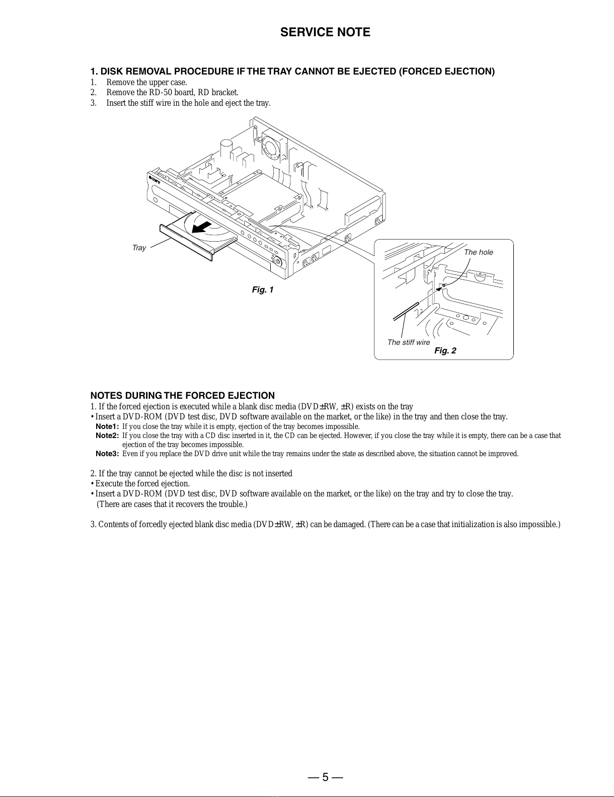
Ways to Use Your DVD Recorder
Remote cable box or satellite receiver control – Set top box control
,Connect the supplied set top box controller
to have the recorder change the channel of
your cable box or satellite receiver during a
timer recording (page 14).
Quick access to recorded titles – Title List
,Display the Title List to see all of the titles
on the disc, including recording date,
channel, recording mode and thumbnail
image (page 32). The recorder will
automatically take program label
information from the XDS (Extended Data
Service)* and display it as the title name
(page 32).
* not available in some areas.
Play the beginning of a title while it is being recorded – Chasing Playback
,If you are using a DVD-RW (VR mode),
you can watch a program from the
beginning while it is being recorded
(page 57).
103 CH 103!
1.5/4.7GB
Sort
Date
Title
Number
My Movies
TITLE LIST
ORIGINAL
1 2ch 1:00PM - 2:00PM
Wed 9/15 1:00PM( 1H00M)SP
2 5ch 8:00PM - 9:00PM
Fri 9/17 8:00PM( 1H00M)SLP
3 12ch 9:00AM - 9:30AM
Sat 9/25 9:00AM( 0H30M)EP
4 3ch 8:00PM - 8:30PM
Sat 9/25 8:00PM( 0H30M)SLP
2ch
5ch
12ch
3ch
Title List
Recording
The game isn’t over
yet, but I’ll start
watching it from the
beginning now.
7
Watching one title while recording another –Simultaneous Rec and Play
,If you are using a DVD-RW (VR mode),
you can watch a previously recorded
program while recording another program
on the same disc (page 57).
Creating your own program –Playlist
,Record a program on a DVD-RW (VR
mode), then delete, move and add scenes at
will to create your own, original program
(page 65).
Dynamic surround sound –TVS
,Enjoy virtual surround sound effects from
just your TV’s speakerswith the TV Virtual
Surround settings when playing a DVD
VIDEO with multichannel audio tracks
such as Dolby Digital (5.1ch) (page 53).
A list of recordable and playable discs is on page 8.
Recording
I think I’ll watch
yesterday’s golf game
now, even though I
am recording a movie.
Original
Playlist
All manuals and user guides at all-guides.com

1-2
8
Quick Guide to Disc Types
Recordable and playable discs
Usable disc versions (as of May 2004)
•4x-speed or slower DVD+RWs
•2x-speed or slower DVD-RWs (Ver.1.1, Ver.1.1
with CPRM*
1
)
•8x-speed or slower DVD+Rs
•8x-speed or slower DVD-Rs (Ver.2.0)
“DVD+RW,” “DVD-RW,” “DVD+R,”and “DVD-R,”
are trademarks.
*1 CPRM (Content Protection for Recordable Media) is
a coding technology that protects copyrights for
images.
*2 Only if the recording mode is SP, HSP, or HQ, and
“Rec Screen Size”is set to “16:9.”
*3 Erasing titles does not free up disc space.
Compatibility with
other DVD players
(finalizing)
Playable only on VR mode
compatible players
(finalization unnecessary)
Playable on most DVD
players (finalization
necessary) (page 36)
Playable on DVD+RW
compatible players
(automatically finalized)
Playable on most DVD
players (finalization
necessary) (page 36)
Playable on DVD+R
compatible players (finalization
necessary) (page 36)
Format in VR
mode
(page 35)
Format in
Video mode
(page 35)
Automatically
formatted
Automatically
formatted
Automatically
formatted
Formatting
(new discs)
Icon
used in
this
manual
Disc
Logo
Type
DVD-
RW
VR
mode
Video
mode
DVD+RW
DVD-R
DVD+R
-
RW
VR
-
RW
Video
+RW
-
R
+R
9
Discs that cannot be recorded on
•4x-speed compatible DVD-RWs (Ver. 1.2/4x)
•DVD-RWs (Ver. 1.0)
•DVD+RWs that are not 2.4x-speed compatible
•Dual layer discs
•8 cm discs
Yes
Yes
Yes
No
No
Yes
Yes
Yes
Yes
Yes
Yes
No
No
No
No
Yes
Yes *2
No
Yes *2
No
Yes
Yes
Yes
Yes
Yes
Yes
Yes
Yes
Yes *3
Yes *3
Yes
No
Yes
No
No
Yes
No
No
No
No
Recording Features Editing Features
Rewrite
(page 41)
Auto
Chapter
(page 78)
Manual
Chapter
(page 65)
Record
16:9 sizes
(page 48)
Change
title name
(page 62)
Delete title
(page 63)
A-B Erase
(page 63)
Playlist
(page 65)
,
continued
10
Playable discs
Discs that cannot be played
•All CD-ROMs (including PHOTO CDs)
•CD-Rs/CD-RWs, other than those recorded in
music CD format, MP3 format, or Video CD
format
•Data part of CD-Extras
•DVD-ROMs
•DVD Audio discs
•DVD-RAMs
•HD layer on Super Audio CDs
•DVD VIDEOs with a different region code (see
below)
•A disc recorded in a color system other than
NTSC, such as PAL or SECAM
zHint
This DVD recorder can play 8 cm CDs and 8 cm DVDs
as well.
Discs such as movies that can be purchased or rented
VIDEO CDs or CD-Rs/CD-RWs in
VIDEO CD/Super VIDEO CD format
Music CDs or CD-Rs/CD-RWs in music CD format
that can be purchased
CD-ROMs/CD-Rs/CD-RWs created on a PC or
similar device in music format containing MP3
audio tracks
Icon
used in
this
manual
Disc
Logo
VIDEO CD
CD
DATA CD
DVD VIDEO
Type Characteristics
DVD
VCD
CD
DATA C D
11
Note on playback operations of DVD VIDEOs/
VIDEO CDs
Some playback operations of DVD VIDEOs/
VIDEO CDs may be intentionally set by software
producers. Since this recorder plays DVD
VIDEOs/VIDEO CDs according to the disc
contents the software producers designed, some
playback features may not be available. Also, see
the instructions supplied with the DVD VIDEOs/
VIDEO CDs.
Region code (DVD VIDEO only)
Your recorder has a region code printed on the rear
of the unit and will only play DVD VIDEOs
(playback only) labeled with identical region
codes. This system is used to protect copyrights.
DVD VIDEOs labeled will also play on this
recorder.
If you try to play any other DVD VIDEO, the
message “Playback prohibited by region code.”
will appear on the TV screen. Depending on the
DVD VIDEO, no region code indication may be
labeled even though playing the DVD VIDEO is
prohibited by area restrictions.
Music discs encoded with copyright protection
technologies
This product is designed to playback discs that
conform to the Compact Disc (CD) standard.
Recently, various music discs encoded with
copyright protection technologies are being
marketed by some record companies. Please be
aware that among those discs, there are some that
do not conform to theCD standard and may notbe
playable by this product.
Notes
•You cannot mix VR mode and Video mode on the same
DVD-RW. To change the disc’s format, reformat the
disc (page 35). Note that the disc’s contents will be
erased after reformatting.
•You cannot shorten the time required for recording
even with high-speed discs. Also, you cannot record on
the disc if the disc is not 1x speed compatible.
•It is recommended that you use discs with “For Video”
printed on their packaging.
•You cannot add new recordings to DVD-Rs or DVD-
RWs (Video mode) that contain recordings made on
other DVD equipment.
•In some cases, you may not be able to add new
recordings to DVD+RWs that contain recordings made
on other DVD equipment. If you do add a new
recording, note that thisrecorder will rewrite the DVD
menu.
•If the disc contains PC data unrecognizable by this
recorder, the data may be erased.
•Some DVD+RWs/DVD+Rs, DVD-RWs/DVD-Rs, or
CD-RWs/CD-Rs cannot be played on this recorder due
to the recording quality or physical condition of the
disc, or the characteristics of the recording device and
authoring software. The disc will not play if it has not
been correctly finalized. For more information, see the
operating instructions for the recording device.
ALL
RDR–XXXX
00V 00Hz
00W NO.
0-000-000-00
XRegion code
All manuals and user guides at all-guides.com

1-3
12
Hookups and Settings
Hooking Up the Recorder
Follow steps 1 to 7 to hook up and adjust the
settings of the recorder.
Notes
•Plug cords securely to prevent unwanted noise.
•Refer to the instructions supplied with the components
to be connected.
•You cannot connect this recorder to a TV that does not
have a video input jack.
•Be sure to disconnect the power cord of each
component before connecting.
Step 1: Unpacking
Check that you have the following items:
•Audio/video cord (pinplug u3 ypinplug u3)
(1)
•Power cord (1)
•Antenna cable (1)
•Remote commander (remote) (1)
•Set top box controller (1)
•Size AA (R6) batteries (2)
Step 2: Connecting the
Antenna Cable and Set Top
Box Controller
Select one of the following antenna hookups. Do
not connect the power cord until you reach “Step
5: Connecting the Power Cord”(page 20).
Using the cable box/satellite
receiver control function
The cable box/satellite receiver control function
can be used with hookup A or B. It allows the
recorder to control a cable box or satellite receiver
via the supplied set top box controller. The
recorder controls channels on the cable box or
satellite receiver for timer recording. You can also
use the recorder’s remote control to change
channels on the cable box/satellite receiver
whenever the cable box/satellite receiver is turned
on, even if the recorder is turned off.
To use the cable box/satellite receiver control
function, you need to connect the set top box
controller and set the code number and output
channel (page 23). After setting up the cable box/
satellite receiver control, check that the recorder
can correctly control the cable box or satellite
receiver (page 26).
Note to CATV system installer (in USA)
This reminder is provided to call the CATV
system installer’s attention to Article 820- 40 of
the NEC that provides guidelines for proper
grounding and, in particular, specifies that the
cable ground shall be connected to the grounding
system of the building, as close to the point of
cable entry as practical.
Notes
•If your antenna is a flat cable (300-ohm twin lead
cable), use an external antenna connector (not
supplied) to connect the antenna to the recorder.
•If you have separate cables for VHF and UHF
antennas, use a UHF/VHF band mixer (not supplied) to
connect the antenna to the recorder.
If you have Hookup
Cable box with a video/audio output
or a satellite receiver A (page 13)
Cable box with an antenna output
only B (page 15)
Cable without cable box, or antenna
only (no cable TV) C (page 14)
13
Hookups and Settings
A: Cable box or satellite receiver with a video/audio output
With this hookup, you can record any channel on the cable box or satellite receiver. Be sure that the
satellite receiver or cable box is turned on.
To watch cable or satellite programs, you need to match the channel on the recorder (L1 or L3) to the
input jack connected to the cable box or satellite receiver (LINE IN 1 or 3).
zHints
•If your cable box or satellite receiver has an S-video jack, you can use an S-video cord (not supplied) instead of the
audio/video cord.
•If you connect an S-video cord to the LINE IN 1 jack, set “Line1 Input”in Video Setup to “S VIDEO”(page 75). If
you connect an S-video cord to the LINE IN 3 jack, set “Line3 Input”in Video Setup to “S VIDEO”(page 74).
VHF/UHF
IN
SETTOP BOX
CONTROL
LINE IN DIGITALOUT
VIDEO
SVIDEO
COAXIAL
OPTICAL
PCM/DTS/
DOLBYDIGITAL
AUDIORL
1
3
LINE OUT
COMPONENT
VIDEO OUT
VIDEO
SVIDEO
AUDIORL
1
2
Y
PB
PR
OUT
~
AC IN
ANT IN
RL
S VIDEO
AUDIO
OUT
VIDEO
OUT
TO TV
SET TOP BOX
CONTROL
LINE IN
VIDEO
S VIDEO
AUDI ORL
1
3
Set top box
controller
(page 12)
to LINE IN
1 or 3
DVD recorder
Audio/video
cord (supplied)
: Signal flow
Place the set top box controller
near the remote sensor on the
cable box/satellite receiver.
Cable box/
satellite receiver
Antenna cable
(supplied)
to antenna input
S-video cord (not
supplied)
to SET TOP BOX
CONTROL
Wall
TV
,
continued
14
B: Cable box with an antenna output only
With this hookup, you can record any channel on the satellite receiver or cable box. Be sure that the
satellite receiver or cable box is turned on.
To watch cable programs, you need to match the channel on the recorder (2ch, 3ch, or 4ch) to the antenna
output channel on the cable box (2ch, 3ch, or 4ch).
VHF/UHF
IN
SETTOP BOX
CONTROL
LINE IN DIGITALOUT
VIDEO
SVIDEO
COAXIAL
OPTICAL
PCM/DTS/
DOLBYDIGITAL
AUDIORL
1
3
LINE OUT
COMPONENT
VIDEO OUT
VIDEO
SVIDEO
AUDIORL
1
2
Y
P
B
P
R
OUT
~AC IN
VHF/UHF
IN
OUT
ANT IN
TO TV
VHF/UHF
IN
OUT
SET TOP BOX
CONTROL
to VHF/UHF IN
Wall
DVD recorder
to VHF/UHF OUT
to antenna
input
Antenna cable
(supplied)
: Signal flow
TV
Place the set top box controller
near the remote sensor on the
cable box/satellite receiver.
to SET TOP
BOX
CONTROL
Set top box
controller
(supplied)
Cable box
15
Hookups and Settings
C: Cable without cable box, or antenna only (no cable TV)
Use this hookup if you watch cable channels without a cable box. Also use this hookup if you are using
a VHF/UHF antenna or separate VHF and UHF antennas.
With this hookup, you can record any channel by selecting the channel on the recorder.
VHF/UHF
IN
SETTOP BOX
CONTROL
LINE IN DIGITALOUT
VIDEO
SVIDEO
COAXIAL
OPTICAL
PCM/DTS/
DOLBYDIGITAL
AUDIORL
1
3
LINE OUT
COMPONENT
VIDEO OUT
VIDEO
SVIDEO
AUDIORL
1
2
Y
P
B
P
R
OUT
~AC IN
VHF/UHF
IN
OUT
DVD recorder
TV
to antenna input
to VHF/UHF IN
to VHF/UHF OUT
Antenna cable (supplied)
: Signal flow
Wall
All manuals and user guides at all-guides.com

1-4
16
Step 3: Connecting the Video Cords
Select one of the following patterns Athrough C, according to the input jack on your TV monitor,
projector, or AV amplifier (receiver). This will enable you to view pictures. Audio connections are
explained in “Step 4: Connecting the Audio Cords”(page 18).
Note
Do not connect more than one type of video cord between the recorder and your TV at the same time.
VHF/UHF
IN
SETTOP BOX
CONTROL
LINE IN DIGITALOUT
VIDEO
SVIDEO
COAXIAL
OPTICAL
PCM/DTS/
DOLBYDIGITAL
AUDIORL
1
3
LINE OUT
COMPONENT
VIDEO OUT
VIDEO
SVIDEO
AUDIORL
1
2
Y
PB
PR
OUT
~
AC IN
VIDEO
AUDIO
INPUT
L
R
INPUT
S VIDEO
P
R
P
B
Y
COMPONENT
VIDEO IN
B
A
C
Audio/video
cord (supplied)
Component video
cord (not supplied)
(yellow)
TV, projector, or AV
amplifier (receiver)
TV, projector, or AV
amplifier (receiver)
(green)
S-video cord
(not supplied)
TV, projector, or AV
amplifier (receiver)
(red) (blue)
(green)
(blue)
(red)
: Signal flow
to COMPONENT
VIDEO OUT
to LINE OUT (VIDEO) 1 or 2 to LINE OUT (S VIDEO) 1 or 2
DVD recorder
17
Hookups and Settings
AConnecting to a video input jack
Connect the yellow plug of the audio/video cord
(supplied) to the yellow (video) jack. You will
enjoy standard quality images.
Note that you cannot use the PROGRESSIVE
button with this connection.
BConnecting to an S VIDEO input
jack
Connect an S-video cord (not supplied). You will
enjoy high quality images.
Note that you cannot use the PROGRESSIVE
button with this connection.
CConnecting to component video
input jacks (Y, PB, PR)
Connect the COMPONENT VIDEO OUT jacks
using a component video cord (not supplied) or
three video cords (not supplied) of the same kind
and length. You will enjoy accurate color
reproduction and high quality images.
If your TV accepts progressive 480p format
signals, you must use this connection and then
press PROGRESSIVE on the remote to send
progressive video signals. For details, see “Using
the PROGRESSIVE button”(page 17).
When playing “wide screen” images
Some recorded images may not fit your TV
screen. To change the aspect ratio, see page 74.
If you are connecting to a VCR
Connect your VCR to the LINE IN (VIDEO) jack
on the recorder (page 29).
Using the PROGRESSIVE button
By using the PROGRESSIVE button on the
remote, you can select the signal format in which
the recorder outputs video signals: Interlace or
Progressive.
Connect the recorder using the COMPONENT
VIDEO OUT jacks (pattern Cabove), and press
PROGRESSIVE repeatedly. “PROGRESSIVE”
appears in the front panel display when the
recorder outputs progressive signals.
◆Progressive
Select this when:
–your TV accepts progressive signals, and,
–the TV is connected to the COMPONENT
VIDEO OUT jacks.
Note that the pictures will not be clear or no
picture will appear if you select progressive signal
output when either of the above conditions is not
met.
◆Interlace
Set to this position when:
–your TV does not accept progressive signals, or,
–your TV is connected to jacks other than the
COMPONENT VIDEO OUT jacks (LINE OUT
(VIDEO) or S VIDEO).
zHint
When you select progressive signal output, you can fine-
tune the signal according to the type of software you are
watching (page 75).
Note
Consumers should note that not all high definition
television sets are fully compatible with this product and
may cause artifacts to be displayed in the picture. In the
case of 480 progressive scan picture problems, it is
recommended that the user switch the connection to the
‘standard definition’output. If there are questions
regarding our TV set compatibility with this model 480p
DVD recorder, please contact our customer service
center.
Yellow
White (L)
Red (R)
Yellow
White (L)
Red (R)
Green
Blue
Red
Green
Blue
Red
18
Step 4: Connecting the Audio Cords
Select one of the following patternsAor B, according to the input jack on your TV monitor, projector,
or AV amplifier (receiver).
This will enable you to listen to sound.
zHint
For correct speaker location, see the operating instructions supplied with the connected components.
Note
Do not connect your TV’s audio output jacks to the LINE IN (AUDIO L/R) jacks at the same time. This will cause
unwanted noise to come from your TV’s speakers.
VIDEO
AUDIO
INPUT
L
R
VHF/UHF
IN
SETTOP BOX
CONTROL
LINE IN DIGITALOUT
VIDEO
SVIDEO
COAXIAL
OPTICAL
PCM/DTS/
DOLBYDIGITAL
AUDIORL
1
3
LINE OUT
COMPONENT
VIDEO OUT
VIDEO
SVIDEO
AUDIORL
1
2
Y
P
B
P
R
OUT
~AC IN
LINE OUT
VIDEO
S VIDEO
AUDI ORL
1
2
B
A
DIGITAL OUT
COAXIAL
OPTICAL
PCM/DTS/
DOLBY DIGITAL
AV amplifier (receiver)
with a decoder
(red)
TV, projector, or AV
amplifier (receiver)
Audio/video
cord (supplied)
: Signal flow
Coaxial digital cord
(not supplied)
to DIGITAL OUT (COAXIAL or
OPTICAL)
to LINE OUT (R-AUDIO-L) 1 or 2
Optical digital cord (not supplied)
Rear (L)
DVD recorder
(white)
(yellow)*
(yellow)
(white)
(red)
[Speakers]
Front (L)
[Speakers]
to coaxial
digital input
Rear (R)
Front (R)
Subwoofer
or
Center
* The yellow plug is used for video signals (page 17).
to optical
digital input
19
Hookups and Settings
AConnecting to audio L/R input
jacks
This connection will use your TV’s or stereo
amplifier’s (receiver’s) two speakers for sound.
Connect using the audio/video cord (supplied).
•Surround effect (page 53)
TV: Dynamic, Wide, Night
Stereo amplifier (receiver): Standard, Night
Note
Do not connect your TV’s audio output jacks to the LINE
IN (AUDIO L/R) jacks at the same time. This will cause
unwanted noise to come from your TV’s speakers.
BConnecting to a digital audio
input jack
If your AV amplifier (receiver) has a Dolby*1
Digital or DTS*2decoder and a digital input jack,
use this connection.
Connect using a coaxial or opticaldigital cord (not
supplied).
•Surround effect
Dolby Digital (5.1ch), DTS (5.1ch)
*1 Manufactured under license from Dolby laboratories.
“Dolby,” “Pro Logic,”and the double-D symbol are
trademarks of Dolby Laboratories.
*2 “DTS”and “DTS Digital Out”are trademarks of
Digital Theater Systems, Inc.
Notes
•After you have completed the connection, make the
appropriate settings under “Audio Connection”in Easy
Setup (page 23). Otherwise, no sound or a loud noise
will come from your speakers.
•The surround sound effects of this recorder cannot be
used with this connection.
Yellow
White (L)
Red (R)
Yellow
White (L)
Red (R) Coaxial cord
Optical cord
All manuals and user guides at all-guides.com

1-5
20
Step 5: Connecting the
Power Cord
Connect the supplied power cord to the AC IN
terminal of the recorder. Then plug the recorder
and TV power cords into an AC outlet. After you
connect the power cord, you must wait for a
short while before operating the recorder. You
can operate the recorder only after the front panel
display lights up and the recorder enters standby
mode.
If you connect additional equipment to this
recorder (page 29), be sure to connect the power
cord only after all connections are complete.
Step 6: Preparing the
Remote
You can control the recorder using the supplied
remote. Insert two size AA (R6) batteries by
matching the 3and #ends on the batteries to the
markings inside the battery compartment. When
using the remote, point it at the remote sensor
on the recorder.
Notes
•If the supplied remote interferes your other Sony DVD
recorder or player, change the command mode number
for this recorder (page 22).
•Use the batteries correctly to avoid possible leakage
and corrosion. Do not touch the liquid with bare hands
should leakage occur. Observe the following:
–Do not use a new battery with an old battery, or
batteries of different manufacturers.
–Do not attempt to recharge the batteries.
–If you do not intend to use the remote for an extended
period of time, remove the batteries.
–If battery leakage occurs, wipe out any liquid inside
the battery compartment, and insert new batteries.
•Do not expose the remote sensor (marked on the
front panel) to strong light, such as direct sunlight or
lighting apparatus. The recorder may not respond to the
remote.
~
AC IN
to AC outlet
to AC IN
1
2
21
Hookups and Settings
Controlling TVs with the remote
You can adjust the remote control’s signal to
control your TV.
If you connected the recorder to an AV amplifier
(receiver), you can also use the supplied remote to
control the AV amplifier’s (receiver’s) volume.
Notes
•Depending on the connected unit, you may not be able
to control your TV or AV amplifier (receiver) with
some or all of the buttons below.
•If you enter a new code number, the code number
previously entered will be erased.
•When you replace the batteries of the remote, the code
number may be reset to the default setting. Set the
appropriate code number again.
1Slide the TV/DVD switch to TV.
2Hold down [/1.
3Enter your TV’s manufacturer code (see
“Code numbers of controllable TVs”
below) using the number buttons.
4Release [/1.
When the TV/DVD switch is set to TV, the
remote performs the following:
Code numbers of controllable TVs
If more than one code number is listed, try
entering them one at a time until you find the one
that works with your TV.
[/1Turns your TV on or off
VOL +/–Adjusts the volume of your
TV
CH +/–Selects the channel on your
TV
TV/VIDEO Switches your TV’s input
source
Number buttons and
SET Selects the channel on your
TV
1 2 3
4 5 6
7 8 9
0
TV/DVD
switch
"/1
VOL +/–
Number
buttons, SET
TV/VIDEO
CH +/–
Manufacturer Code number
Sony 01 (default)
Akai 04
AOC 04
Centurion 12
Coronado 03
Curtis-Mathes 12, 14
Daewoo 04, 22
Daytron 03, 12
Fisher 11
General Electric 04, 06, 10
Gold Star/LG 03, 04, 17
Hitachi 02, 03, 04
J.C.Penney 04, 10, 12
JVC 09
KMC 03
Magnavox 03, 04, 08, 12, 21
Marantz 04, 13
MGA/Mitsubishi 04, 12, 13, 17
NEC 04, 12
Panasonic 06, 19
Philco 02, 03, 04, 08
Philips 08, 21
Pioneer 06, 16
Portland 03
Proscan 10
Quasar 06, 18
Radio Shack 05, 10, 14
RCA 04, 10
Sampo 12
Samsung 03, 04, 12, 20
Sanyo 11, 14
Scott 12
Sears 07, 10, 11
Sharp 03, 05, 18
,
continued
22
Controlling the volume of your AV
amplifier (receiver) with the remote
1Slide the TV/DVD switch to DVD.
2Hold down [/1, and enter the
manufacturer code (see the table below)
for your AV amplifier (receiver) using the
number buttons.
3Release [/1.
The VOL +/–buttons control the AV
amplifier’s volume.
If you want to control the TV’s volume, slide
the TV/DVD switch to TV.
zHint
If you want to control the TV’s volume even when the
TV/DVD switch is set to DVD, repeat the steps above
and enter the code number 90 (default).
Code numbers of controllable AV amplifiers
(receivers)
If more than one code number is listed, try
entering them one at a time until you find the one
that works with your AV amplifier (receiver).
If you have a Sony DVD player or
more than one Sony DVD recorder
If the supplied remote interferes with your other
Sony DVD recorder or player, set the command
mode number for this recorder and the supplied
remote to one that differs from the other Sony
DVD recorder or player.
The default command mode setting for this
recorder and the supplied remote is DVD3.
Sylvania 08, 12
Teknika 03, 08, 14
Toshiba 07, 18
Wards 03, 04, 12
Yorx 12
Zenith 14, 15
Manufacturer Code number
1 2 3
4 5 6
7 8 9
0
TV/DVD
switch
"/1
VOL +/–
Number
buttons, SET
Manufacturer Code number
Sony 78, 79, 80, 91
Denon 84, 85, 86
Kenwood 92, 93
Onkyo 81, 82, 83
Pioneer 99
Sansui 87
Technics 97, 98
Yamaha 94, 95, 96
1 2 3
4 5 6
7 8 9
0
SYSTEM
MENU
M/m,
ENTER
COMMAND
MODE
ORETURN
23
Hookups and Settings
1Press SYSTEM MENU.
The System Menu appears.
2Select “SETUP,”and press ENTER.
3Select “Options,”and press ENTER.
4Select “Command Mode,”and press
ENTER.
5Select the Command mode (DVD1, DVD2,
or DVD3), and press ENTER.
6Slide the COMMAND MODE switch on the
remote so it matches the mode you
selected above.
To return to the previous step
Press ORETURN.
Step 7: Easy Setup
Follow the steps below to make the minimum
number of basic adjustments for using the
recorder. If you do not complete Easy Setup, it
will appear each time you turn on your recorder.
Settings are made in the following order.
m
m
m
m
m
m
1Turn on the TV.
2Press [/1.
The recorder turns on.
SETUP
Settings
Video
Audio
Features
Options
Easy Setup
Tuner Preset
Set VCR Plus+ Channels
Clock
Set Top Box Control
Language
Settings
Video
Audio
Features
Options
Easy Setup
Format DVD :
Dimmer :
Auto Display :
Command Mode :
Factory Setup
VR
Normal
On
DVD3
SETUP
Settings
Video
Audio
Features
Options
Easy Setup
Format DVD :
Dimmer :
Auto Display :
Command Mode :
Factory Setup
VR
Normal
On
DVD3
SETUP
DVD1
DVD2
DVD3
OSD Language Setup
Clock Setup
Cable Box/Sat. Control Setup
Tuner and Channel Setup
TV Type Setup
Audio Connection Setup
Finished!
1 2 3
4 5 6
7 8 9
0
"/1
</M/m/,,
ENTER
ORETURN
CH +/–
Number
buttons
,
continued
All manuals and user guides at all-guides.com
all-guides.com

1-6
24
3Switch the input selector on your TV so that
the signal from the recorder appears on
your TV screen.
“Initial settings necessary to operate the DVD
recorder will be made. You can change them
later using Setup. Before you start, check that
you have made all necessary connections.”
appears.
•Ifthis messagedoesnot appear,select“Easy
Setup”from “SETUP”in the System Menu
to run Easy Setup. For details, see “Settings
and Adjustments”on page 69.
4Press ENTER.
The Setup Display for selecting the language
used in the on-screen display appears.
5Select a language, and press ENTER.
The Setup Display for clock setting appears.
6Select “Manual,”and press ENTER.
Press M/mto set the month and press ,. Set
the day, year, hour, and minutes in the same
way. The day of the week is set automatically.
If you used antenna hookup C (page 15), you
can select “Auto.”The recorder will
automatically search for a channel that carries
a time signal when you turn off the recorder
after finishing Easy Setup.
Once the clock is set, the Setup Display for
cable box/satellite receiver control appears.
7Set the cable box/satellite receiver
control, and press ENTER.
If you want to use the cable box/satellite
receiver control (page 14), select “Yes.”
If you do not have a cable box, select “No,”
then go to step 11.
8Enter the brand code of your cable box/
satellite receiver.
See “Cable Box/Satellite Receiver Brand
Code”(page 96).
Use M/mto select the number and </,to
move the cursor.
9Press ENTER.
10Select the cable box output channel.
If you connect your cable box or satellite
receiver to the recorder’s audio/video input
(page 13), select “Line1,” “Line2,”or
“Line3,”then go to step 13.
Language 1/6
Select the screen Language.
English
Fran çais
Español
EASY SETUP
EASY SETUP
Clock 2/6
Select a method for setting the clock.
If you select "Auto", this recorder will look for a
time signal when you turn it off.
Auto
Manual
Set Top Box Control 3/6
Do you want to control your set top box
with this recorder?
(Changes to the current setting will erase all timer settings.)
Ye s
No
EASY SETUP
Set Top Box Control 3/6
Enter the brand code of your set top box.
- - - -
EASY SETUP
Set Top Box Control 3/6
Select input line or Set Top Box's output channel.
Line1
Line2
Line3
Ch2
Ch3
Ch4
EASY SETUP
25
Hookups and Settings
If you connect the satellite receiver or cable
box to the recorder’s antenna input (page 14),
select “Ch2,” ‘Ch3,”or “Ch4”and press
ENTER, then go to step 13. See the
instructions supplied with your cable box to
confirm the cable box’s antenna output
channel.
11Select whether or not you have a cable
connection.
If you use an antenna only (no cable TV),
select “Antenna.”
If you use a cable connection without a cable
box, select “Cable.”
12Press ENTER.
The Tuner Preset function automatically starts
searching for all of the receivable channels
and presets them.
To set the channels manually, see page 71.
After the Tuner Preset is finished, the Setup
Display for selecting the aspect ratio of the
connected TV appears.
13Select the setting that matches your TV
type.
“4:3 Letter Box”: For standard TVs.
Displays “wide screen”pictures with bands
on the upper and lower sections of the screen.
“4:3 Pan Scan”: For standard TVs.
Automatically displays “wide screen”
pictures on the entire screen and cuts off the
sections that do not fit.
“16:9”: For wide-screen TVs or standard TVs
with a wide screen mode.
For details, see “TV type”on page 74.
14Press ENTER.
The Setup Display for selecting the type of
jack used to connect to your amplifier
(receiver) appears.
15Select the type of jack (if any) you are
using to connect to an amplifier (receiver),
and press ENTER.
If you did not connect an AV amplifier
(receiver), select “No,”then go to step 19.
If you connected an AV amplifier (receiver)
using just an audio cord, select “Yes: LINE
OUT (R-AUDIO-L),”then go to step 19.
If you connected an AV amplifier (receiver)
using either a digital optical or coaxial cord,
select “Yes: DIGITAL OUT.”
16Select the type of Dolby Digital signal you
wish to send to your amplifier (receiver).
If your AV amplifier (receiver) has a Dolby
Digital decoder, select “Dolby Digital.”
Otherwise, select “D-PCM.”
Tuner Preset 4/6
Select the way in which you will receive channels.
Antenna
Cable
EASY SETUP
EASY SETUP
Tuner Preset 4/6
Searching for receivable channels.
Please wait. Ch45
EASY SETUP
TV Type 5/6
Select your TV screen type.
16 : 9
4 : 3 Letter Box
4 : 3 Pan Scan
EASY SETUP
Audio Connection 6/6
Is this recorder connected to an amplifier (receiver)?
Select the type of jack you are using.
Yes :
LINE OUT(R-AUDIO-L)
Yes :
DIGITAL OUT
No
EASY SETUP
Audio Connection 6/6
Dolby Digital
D-PCM
Dolby Digital
,
continued
26
17Press ENTER.
The Setup Display for the DTS signal appears.
18Select whether or not you wish to send a
DTS signal to your amplifier (receiver),
and press ENTER.
If your AV amplifier (receiver) has a DTS
decoder, select “On.”Otherwise, select “Off.”
19Press ENTER when “Finish”appears.
Easy Setup is finished. All connections and
setup operations are complete.
If you use the cable box/satellite receiver
control, check that the control works correctly
(see below).
To return to the previous step
Press ORETURN.
zHint
If you want to run Easy Setup again, select “Easy Setup”
in the Setup Display (page 81).
Notes
•If there are only a few channels in your area that carry
time signals, setting the clock automatically may take
up to about 20 minutes after the recorder turns off. If
nothing happens even after you wait about 20 minutes,
set the clock manually in “Clock” of “Settings”
(page 72).
•To record TV programs using the timer, you must set
the clock accurately.
•If you use an S-video cord to connect your cable box or
satellite receiver, set “Line1 Input”or “Line3 Input”in
Video Setup to “S Video”(page 75).
Checking the cable box/satellite
receiver control setting
1Point the remote at the recorder (not at the
cable box/satellite receiver.)
2Press CH +/–and check that the channel
changes on the cable box/satellite receiver
window.
3Press the number buttons and check that
the channel changes on the cable box/
satellite receiver window.
To fix the set top box controller to your cable
box/satellite receiver
Once you have confirmed that the set top box
controller controls your cable box or satellite
receiver, fix it in place.
1Remove the backing on the double-sided tape.
2Attach it so that the cable mouse is directly
above the remote control sensor on your cable
box/satellite receiver.
If you cannot get the recorder to control your
cable box/satellite receiver
Check the settings at “Set Top Box Control”in
Settings Setup (page 73).
Check the connection and position of the cable
mouse (page 13).
If your cable box or satellite receiver still does not
operate with this recorder, contact your cable
company to see if they can provide you with a
compatible cable box or satellite receiver.
Audio Connection 6/6
DTS
On
Off
EASY SETUP
EASY SETUP
Easy Setup is finished.
Finish
27
Hookups and Settings
Setting Up the VCR Plus®
System
Setting up your recorder involves coordinating the
TV channel number (the number you turn to on
your TV or recorder to watch a program) with the
guide channel (the number that’s assigned to that
channel in your TV program guide).
To find the guide channel numbers, look at the
“Channel Line-up Chart”in the program guide for
your area that features VCR PlusCode numbers.
Use the Channel Line-up Chart to coordinate the
guide channel number with the TV channel
number. For example, if HBO is listed in the
Channel Line-up Chart as channel 33, and the
recorder receives HBO on channel 5, coordinate
these numbers using the following procedure.
1Press SYSTEM MENU while the recorder is
stopped.
2Select “SETUP,”and press ENTER.
3Select “Settings,”and press ENTER.
4Select “Set VCR Plus+ Channels,”and
press ENTER.
5Select “Guide CH –TV CH,”and press
ENTER.
6Enter the guide channel number assigned
in the program guide using the number
buttons, and press SET.
7Enter the TV channel number using the
number buttons, and press SET.
1 2 3
4 5 6
7 8 9
0
</M/m/,,
ENTER
ORETURN
SYSTEM
MENU
Number
buttons, SET
SYSTEM MENU
TITLE LIST
TIMER
TIMER LIST
SETUP
SETUP
Settings
Video
Audio
Features
Options
Easy Setup
Tuner Preset
Set VCR Plus+ Channels
Clock
Set Top Box Control
Language
Settings - Set VCR Plus+ Channels
----
Channel list
Guide CH TV CH
- - - -
Settings - Set VCR Plus+ Channels
Guide CH TV CH
- - ---- - -
- - - -
Settings - Set VCR Plus+ Channels
Guide CH TV CH
- - ---- - -
33 33
Settings - Set VCR Plus+ Channels
Guide CH TV CH
- - ---- - -
33 5
,
continued
All manuals and user guides at all-guides.com

1-7
28
If you connected a cable box or satellite
receiver to the recorder and set “Set Top Box
Control”to “On,”enter the TV channel
number on your cable box.
If you connected a cable box and set “Set Top
Box Control”to “Off,”enter the cable box
output channel (Usually 2ch, 3ch, or 4ch). See
the instructions supplied with your cable box
to confirm the cable box’s output channel.
8Repeat steps 5 to 7 for each guide channel
number that does not match the TV channel
number.
9Press SYSTEM MENU repeatedly to exit the
menu.
To return to the previous step
Press ORETURN.
To check the channel settings
When displaying the “Set VCR Plus+ Channels”
menu, select “Channel List,”then press ENTER.
The display lists the channels for which the guide
channel number does not match the TV channel
number.
To go to the next page, press m.
To return to the previous page, press M.
Settings - VCR Plus+ Channel List
Guide CH TV CH
2
4
6
10
11
25
28
-
-
-
-
-
-
-
21
32
9
121
13
36
2
Guide CH TV CH
45
53
- -
- -
- -
- -
- -
-
-
-
-
-
-
-
18
5
- -
- -
- -
- -
- -
Close
Page1
29
Hookups and Settings
Connecting a VCR or Similar Device
After disconnecting the recorder’s power cord from an AC outlet, connect a VCR or similar recording
device to the LINE IN jacks of this recorder.
See also the instruction manual supplied with the connected equipment.
To record on this recorder, see “Recording From a VCR or Similar Device”(page 49).
Connecting to the LINE IN 1 or 3 jacks
If the equipment has an S-video jack, you can use an S-video cord instead of an audio/video cord.
VHF/UHF
IN
SETTOP BOX
CONTROL
LINE IN DIGITALOUT
VIDEO
SVIDEO
COAXIAL
OPTICAL
PCM/DTS/
DOLBYDIGITAL
AUDIORL
1
3
LINE OUT
COMPONENT
VIDEO OUT
VIDEO
SVIDEO
AUDIORL
1
2
Y
PB
PR
OUT
~
AC IN
LINE OUTPUT
S Video
AUDIO
RL
VIDEO
LINE IN
VIDEO
S VIDEO
AUDIORL
1
3
VCR, etc.
DVD recorder
Audio/video cord
(not supplied)
S-video cord
(not supplied)
: Signal flow
to LINE IN 1 or 3
,
continued
30
Connecting to the LINE 2 IN jacks on the front panel
Connect a VCR or similar recording device to the LINE 2 IN jacks of this recorder. If the equipment has
an S-video jack, you can use an S-video cord instead of an audio/video cord.
zHint
When the connected equipment outputs only monaural sound, use audio cables that distribute monaural sounds to left/
right channels (not supplied).
Notes
•Do not connect the yellow LINE IN (VIDEO) jack when using an S-video cord.
•Do not connect the output jack of this recorder to another equipment’s input jack with the other equipment’s output
jack connected to the input jack of this recorder. Noise (feedback) may result.
•Pictures containing copy protection signals that prohibit any copying cannot be recorded.
•If you pass the recorder signals via the VCR, you may not receive a clear image on your TV screen.
Be sure to connect your VCR to the DVD recorder and your TV in the order shown below. To watch videotapes, watch
the tapes through a second Line input on your TV.
•If you disconnect the recorder’s power cord, you will not be able to view the signals from the connected VCR.
•Do not connect more than one type of video cord between the recorder and your TV at the same time.
OUTPUT
S VIDEO AUDIO
LR
VIDEO
S VIDEO VIDEO
LINE 2 IN
L (MONO) AUDIO R
VCR, etc.
Audio/video cord
(not supplied)
S-video
cord (not
supplied)
to LINE 2 IN DVD recorder
: Signal flow
VCRDVD recorder TV
VCR DVD recorder TV
LINE IN 1
LINE IN 2
31
Guide to Displays
Guide to Displays
Using the On-Screen Menus
Thissection introducesthe SystemMenu,TOOLS
menu, and sub-menu. By using these displays, you
can perform most of the recorder’s operations.
System Menu
The System Menu appears when you press
SYSTEM MENU, and provides entries to all of
the recorder’s main functions, such as timer
recording and setup.
Select an option by pressing M/mand ENTER.
ATITLE LIST (page 32):
Turns on the Title List menu, which shows
recorded titles on the disc.
BTIMER (page 41):
Allows you to set a new timer recording
setting.
CTIMER LIST (page 44):
Turns on the Timer List menu, which allows
you to check, change, or cancel timer settings.
DSETUP (page 69):
Turns on the Setup Display, which allows you
to set up the recorder to suit your preferences.
Sub-menu
The sub-menu appears when you select an item
from a list menu (e.g. a title from the Title List
menu), and press ENTER. The sub-menu displays
options applicable only to the selected item. The
displayed options differ depending on the
situation and disc type.
Select an option by pressing M/mand ENTER.
Example: The Title List menu
+
R
DVD
VCD CD
DATA CD
-
RW
VR
-
RWVideo
+
RW
-
R
1 2 3
4 5 6
7 8 9
0
Number
buttons, SET
TOOLS
</M/m/,,
ENTER
SYSTEM
MENU
ORETURN
SYSTEM MENU
TITLE LIST
TIMER
TIMER LIST
SETUP
1 2ch 1:00PM - 2:00PM
2 5ch 8:00PM - 9:00PM
3 12ch 9:00AM - 9:30AM
4 3ch 8:00PM - 8:30PM
5 25ch 8:00PM - 8:30PM
6 L2 9:00PM - 9:30PM
7 8ch 9:00PM - 9:30PM
8 125ch 10:00AM - 10:30AM
9/15
9/17
9/25
9/25
10/15
10/19
10/26
10/28
Wed
Fri
Sat
Sat
Fri
Tu e
Tu e
Thu
Sort
1.5/4.7GB
My Movies
TITLE LIST
ORIGINAL
Date
Title
Number
Close
Play
Play Beginning
Erase
Protect Title
Title Name
Set Thumbnail
A-B Erase
Options for the selected item
,
continued
All manuals and user guides at all-guides.com

1-8
32
TOOLS
The TOOLS menu appears when you press
TOOLS, and displays options applicable to the
entire disc (e.g. disc protection), recorder (e.g.
audio settings during recording), or multiple items
on a list menu (e.g. erasing multiple titles). The
displayed options differ depending on the
situation and disc type.
Select the option by pressing M/mand ENTER.
Example 1: When you press TOOLS while the
Title List menu is turned on.
Example 2: When you press TOOLS while a
DVD-RW (VR mode) is playing.
To return to the previous display
Press ORETURN.
Using the Title List
The titles of programs recorded on a disc are
displayed in the Title List.
1Press ZOPEN/CLOSE, and place a disc on
the disc tray.
2Press ZOPEN/CLOSE to close the disc
tray.
Wait until “LOAD”disappears from the front
panel display.
3Press TITLE LIST.
To show the list in greater detail (zoom), press
ZOOM+.
1 2ch 1:00PM - 2:00PM
2 5ch 8:00PM - 9:00PM
3 12ch 9:00AM - 9:30AM
4 3ch 8:00PM - 8:30PM
5 25ch 8:00PM - 8:30PM
6 L2 9:00PM - 9:30PM
7 8ch 9:00PM - 9:30PM
8 125ch 10:00AM - 10:30AM
9/15
9/17
9/25
9/25
10/15
10/19
10/26
10/28
Wed
Fri
Sat
Sat
Fri
Tue
Tue
Thu
Sort
1.5/4.7GB
My Movies
TITLE LIST
ORIGINAL
Date
Title
Number
TOOLS
Close
Disc Info.
Erase Titles
Playlist
Create Playlist
Options for the disc or menu
TOOLS
Close
Stop
Disc Info.
Erase Title
Protect Title
Options for the disc or picture
+
RW
-
RW
VR
-
RW
Video
-
R
+
R
1 2 3
4 5 6
7 8 9
0
TOOLS
</M/m/,,
ENTER
CURSOR
MODE
Z OPEN/
CLOSE
ZOOM +/–
TITLE LIST
With the recording side facing down
33
Guide to Displays
Standard Title List (Example: DVD-RW in VR
mode)
m
ATitle type (DVD-RW in VR mode only):
Displays the title type, Original or Playlist.
BSort buttons:
Sorts the title order (see below).
CZooming indicator:
Shows the current zoom status.
DDisc name (page 35)
EDisc space (remainder/total)
FTitle information:
Displays the title number, title name, and
recording date.
“z”(red) indicates that the title is currently
being recorded.
“”indicates the protected title.
GScroll bar:
Appears when all of the titles do not fit on the
list. To view the hidden titles, press M/m.
HTitle’s thumbnail picture
To scroll the list display by page (Page mode)
Press CURSOR MODE while the list display is
turned on. The display enters Page mode. Each
time you press M/m, the entire Title List changes
to the next/previous page of titles.
To return to the Cursor mode, press CURSOR
MODE again.
About the Title List for DVD-RWs (VR mode)
You can switch the Title List to show Original or
Playlist.
While the Title List menu is turned on, press
TOOLS and select either “Original”or “Playlist,”
and press ENTER. “PLAYLIST”appears on the
front panel display when “Playlist”is selected.
For details, see “Edit options for DVD-RWs (VR
mode)”(page 61).
To change the title order (Sort)
Press <while the Title List menu is turned on to
move the cursor to the Sort column. PressM/mto
select the item, and press ENTER.
To change a title thumbnail picture
(Thumbnail) (DVD-RW in VR mode only)
You can select a favorite scene for the thumbnail
picture shown in the Title List menu.
1Press TITLE LIST while a disc is in the
recorder, and press ZOOM+.
2Select a title whose thumbnail picture you
want to change, and press ENTER.
3Select “Set Thumbnail”from the sub-menu,
and press ENTER.
The selected title starts to play in the
background.
4While watching the playback picture, press
H PLAY, XPAUSE, or m/Mto select
the scene you want to set for a thumbnail
picture, and press ENTER.
The scene is set for the title’s thumbnail
picture.
To turn off the Title List
Press TITLE LIST.
1 2ch 1:00PM - 2:00PM
2 5ch 8:00PM - 9:00PM
3 12ch 9:00AM - 9:30AM
4 3ch 8:00PM - 8:30PM
5 25ch 8:00PM - 8:30PM
6 L2 9:00PM - 9:30PM
7 8ch 9:00PM - 9:30PM
8 125ch 10:00AM - 10:30AM
9/15
9/17
9/25
9/25
10/15
10/19
10/26
10/28
Wed
Fri
Sat
Sat
Fri
Tu e
Tu e
Thu
Sort
1.5/4.7GB
My Movies
TITLE LIST
ORIGINAL
Date
Title
Number
1.5/4.7GB
Sort
Date
Title
Number
My Movies
TITLE LIST
ORIGINAL
1 2ch 1:00PM - 2:00PM
Wed 9/15 1:00PM( 1H00M)SP
2 5ch 8:00PM - 9:00PM
Fri 9/17 8:00PM( 1H00M)SLP
3 12ch 9:00AM - 9:30AM
Sat 9/25 9:00AM( 0H30M)EP
4 3ch 8:00PM - 8:30PM
Sat 9/25 8:00PM( 0H30M)SLP
2ch
5ch
12ch
3ch
“Zoomed”Title List
Order Sorted
Date in order of when the titles were
recorded. The title that is recorded
most recently is listed at the top.
Title in alphabetical order.
Number in order of recorded title number.
,
continued
34
zHint
After recording, the first scene of the recording (the title)
is automatically set as the thumbnail picture.
Notes
•The Title List may not appear for discs created on other
DVD recorders.
•Letters that cannot be displayed are replaced with an
“*”.
•Title thumbnail pictures are displayed only on this
recorder.
•It may take a few seconds for the thumbnail pictures to
be displayed.
•After editing, the title thumbnail picture may change to
the first scene of the recording (title).
Using the “Disc Info”
Screen (disc settings)
With the Disc Information display, you can check
the disc type and remaining disc space. Also, you
can perform operations such as formatting and
finalizing (page 35).
1Press ZOPEN/CLOSE, and place a disc on
the disc tray.
2Press ZOPEN/CLOSE to close the disc
tray.
Wait until “LOAD”disappears from the front
panel display.
3Press TOOLS.
The TOOLS menu appears.
4Select “Disc Info.,”and press ENTER.
Items in the display differ depending on the
disc type or recording format.
+
RW
-
RW
VR
-
RW
Video
-
R
+
R
1 2 3
4 5 6
7 8 9
0
TOOLS
</M/m/,,
ENTER
Z OPEN/
CLOSE
With the recording side facing down
35
Guide to Displays
Example: DVD-RW (VR mode)
A“Disc Name”
B“Media”: Disc type
C“Format”: Recording format type (DVD-
RW only)
D“Title no.”: Total number of titles
E“Protected”: Indicates whether protectionis
set (DVD-RW in VR mode only)
F“Date”: Dates of when the oldest and the
most recent titles were recorded
G“Continuous Rem. Time”/“Remainder”
(approximate)
•The longest continuous recording time in
each of the recording modes
•Disc space bar
•Remaining disc space/total disc space
HDisc setting buttons (page 35)
•“Disc Name”
•“Protect Disc”
•“Finalize”/“Unfinalize”
•“Erase All”
•“Format”
Available settings differ depending on the disc
type.
zHint
For DVD-RWs (Video mode) and DVD+RWs, you can
check free space and title location on the disc using the
Disc Map display (page 64).
Note
On this model, 1 GB (read “gigabyte”) is equivalent to 1
billion bytes. The larger the number, the larger the disc
space.
Labeling, protecting, or formatting
a disc
You can execute options effective for the entire
disc using the Disc Information display.
1Press TOOLS while the disc is in the
recorder.
The TOOLS menu appears.
2Select “Disc Info.,”and press ENTER.
Example: When the inserted disc is a DVD-
RW (VR mode).
3Select an option, and press ENTER.
“Disc Name”: Labels a disc. Enter the disc
name in the “Input Disc Name”display
(page 39).
“Protect Disc”(DVD-RW in VR mode only):
Protects all titles on the disc. To cancel the
protection, select “Don’t Protect.”
“Erase All”(DVD-RW/DVD+RW only):
Erases all titles on the disc (except the
protected titles).
“Format”(DVD-RW/DVD+RW only):
Erases all contents of the disc to make a blank
disc. For DVD-RWs, select a recording
format (VR or Video) according to your
needs.
zHints
•You can set protection for individual titles (page 62).
•By reformatting, you can change the recording format
on DVD-RWs, or record again on DVD-RWs (Video
mode) that have been finalized.
Note
You can enter up to 64 characters for a disc name. The
disc name may not appear when the disc is played on
other DVD equipment.
Disc Information
DiscName Movie
Close
Media DVD-RW Format VR
Title no. Original 3 / Playlist 2
Protected Not Protected
Date 9/15/2003 ~ 10/28/2003
HQ : 0H30M
LP : 1H30M
HSP : 0H45M
EP : 2H00M
SP : 1H00M
2. 3 / 4. 7GB
SLP : 3H00M
Remainder
Disc Name
Format
Erase All
Finalize
Protect Disc
-
RW
VR
-
RWVideo
+
RW
-
R
+
R
Disc Information
DiscName
Close
Media DVD-RW Format VR
Title no. Original 3 / Playlist 2
Protected Not Protected
Date 9/15/2003 ~ 10/28/2003
HQ : 0H30M
LP : 1H30M
HSP : 0H45M
EP : 2H00M
SP : 1H00M
2. 3 / 4. 7GB
SLP : 3H00M
Remainder
Disc Name
Format
Erase All
Finalize
Protect Disc
,
continued
All manuals and user guides at all-guides.com

1-9
36
Finalizing a disc (preparing a disc
for playback on other equipment)
Finalizing is necessary when you play discs
recorded with this recorder on other DVD
equipment.
When you finalize a DVD+RW, DVD-RW
(Video mode), DVD+R, or DVD-R, a DVD menu
will be automatically created, which can be
displayed on other DVD equipment.
Before finalizing, check the differences between
the disc types in the table below.
Differences between the disc types
1Press TOOLS while the disc is in the
recorder.
The TOOLS menu appears.
2Select “Disc Info.,”and press ENTER.
The Disc Information display appears.
3Select “Finalize,”and press ENTER.
The display shows the approximate time
required for finalizing and asks for
confirmation.
4Select “OK,”and press ENTER.
The recorder starts finalizing the disc.
To unfinalize a DVD-RW (VR mode)
If you cannot record or edit on a DVD-RW (VR
mode) that has been finalized with other DVD
equipment (a message appears), unfinalize the
disc by selecting “Unfinalize”in step 3 above.
zHint
You can check whether the disc has been finalized or not.
If you cannot select “Finalize”in step 3 above, the disc
has already been finalized.
Notes
•Depending on the condition of the disc, recording, or
the DVD equipment, discs may not play even if the
discs are finalized.
•The recorder may not be able to finalize the disc if it
was recorded on another recorder.
Discs are automatically finalized when
removed from the recorder. However,
you may need to finalize the disc for
certain DVD equipment, or if the
recording time is short. You can edit or
record on the disc even after finalizing.
Finalizing is unnecessary when playing
a disc on VR format compatible
equipment.
Even if your other DVD equipment is
VR format compatible, you may need to
finalize the disc, especially if the
recording time is short. You can edit or
record on the disc even after finalizing.
Finalizing is necessary when playing on
any equipment other than this recorder.
After finalizing, you cannot edit or
record on the disc. If you want to record
on it again, reformat the disc (page 35).
However, all recorded contents will be
erased.
Finalizing is necessary when playing on
any equipment other than this recorder.
After finalizing, you cannot edit or
record on the disc.
-
RW
VR
-
RW
Video
+RW
-
R
+R
+RW
-
RW
VR
-
RW
Video
-
R
+R
Finalize
About xx min is needed for finalizing this disc.
Cannot cancel finalizing during transaction.
Do you want to finalize?
OK Cancel
37
Guide to Displays
Checking the Play
Information and Playing
Time
You can check the playing time and remaining
time of the current title, chapter, or track. Also,
you can check the disc name recorded on the disc.
Press DISPLAY repeatedly.
Each time you press the button, the display
changes as follows:
The displays differ depending on the disc type or
playing status.
◆Display 1
Example: When playing a DVD VIDEO
ATitle number/name
(Track number for CDs/VIDEO CDs without
PBC, scene number for VIDEO CDs with
PBC, track number/name for DATA CDs)
BAvailable functions for DVD VIDEOs
( angle/ audio/ subtitle, etc.)
CThe current selected function or audio
setting (appears only temporarily)
DThe current selected angle
Example: Dolby Digital 5.1 ch
◆Display 2
Example: When playing a DVD-RW (VR mode)
ADisc type*
2
/format (page 8)
BTitle type (Original or Playlist) (page 61)
CPlay mode
DRecording mode (page 40)
EPlaying status bar*
3
FTitle number (chapter number*
1
) (page 58)
(Track number for CDs/VIDEO CDs without
PBC, scene number for VIDEO CDs with
PBC, track number (album number*
1
) for
DATA CDs)
GCD text (album name) appears when text is
recorded on a CD.
HPlaying time (remaining time*
1
)
*1Displayed when you press TIME/TEXT repeatedly.
*2Displays Super VCDs as “SVCD”, DATA CDs as
“CD”.
*3Does not appear with VCDs, or DATA CDs.
+R
DVD
VCD CD
DATA CD
-
RW
VR
-
RW
Video
+RW
-
R
1 2 3
4 5 6
7 8 9
0
TIME/TEXTDISPLAY
Title/track information (Display 1)
Play mode/time information (Display 2)
(Display off)
m
m
Title 1
1 : English DolbyDigital 2/0Angle3(5)
1 : English DolbyDigital 3/2.1
Rear (L/R)
Front (L/R) + Center LFE (Low Frequency
Effect)
0:00:45
T1SP
Original
DVD -RW
VR
Movies
,
continued
38
zHints
•If “DTS”is set to “Off”in Audio Setup, the DTS track
selection option will not appear on the screen even if
the disc contains DTS tracks (page 77).
•When “Auto Display”is set to “On”(default) in
Options Setup (page 80), playback information
automatically appears when the recorder is turned on,
etc.
Notes
•The recorder can only display the first level of a CD’s
text, such as the disc name.
•The letters or symbols that cannot be displayed are
replaced with “*.”
Checking the playing/remaining
time
You can view the playing or time information
displayed on the TV screen and the front panel
display.
Press TIME/TEXT repeatedly.
The displays differ depending on the disc type or
playing status.
◆Front panel display
Example: When playing a DVD
Example: When playing a CD
Notes
•The recorder can only display the first level of a CD’s
text, such as the disc name.
•The letters or symbols that cannot be displayed are
replaced with “*.”
•Playing time of MP3 audio tracks may not be displayed
correctly.
Playing time and number of the current title
Remaining time of the current title
Playing time and number of the current chapter
Remaining time of the current chapter
Track playing time and the current track/index
number
Remaining time of the current track
Remaining time of the disc
CD text (when available)
Playing time of the disc
m
m
m
m
39
Guide to Displays
How to Enter Characters
You can label a title, disc, or program by entering
characters. You can enter up to 64 charactersfor a
title or disc name, but the actual number of
characters displayed in the menus such as the Title
List will vary. When the display for entering
characters appears, follow the steps below.
1Press </M/m/,to move the cursor to
the right of the screen and select “A”
(upper-case), “a”(lower-case), or
“Symbol,”and press ENTER.
The characters of the selected type are
displayed.
2Press </M/m/,to select the character
you want to enter, and press ENTER.
The selected character appears at the top of
the display.
Example: Input Title Name
The type of characters will change according
to the language you select in Easy Setup.
Some languages allow you to enter an accent
mark.
To enter a letter with an accent mark, select an
accent followed by the letter.
Example: Select“` ”and then “a” to enter “à.”
To insert a space, select “Space.”
3Repeat steps 1 and 2 to enter the
remaining characters.
To erase a character, move the cursor to the
right of the character at the input row. Select
“Back”and press ENTER.
To insert a character, move the cursor to the
right of the point where you want to insert the
character. Select the character and press
ENTER.
To erase all of the characters, select “Clear
All”and press ENTER.
4Select “Finish,”and press ENTER.
To cancel the setting, select “Cancel.”
To use the number buttons
You can also use the number buttons to enter
characters.
1In step 2 above, press the number buttons
repeatedly to select a character.
Example:
Press the number 3 button once to enter “D.”
Press the number 3 button three times to enter
“F.”
2Press SET and select the next character.
3Select “Finish”and press ENTER.
1 2 3
4 5 6
7 8 9
0
</M/m/,,
ENTER
Number
buttons, SET
K
"A"
"a"
Symbol
Cancel
Finish
Space
Clear All
Back
,. - 1
BA C 2
ED F 3
HG I 4
KJ L5
1
2
3
4
5
NM O 6
QP R S
UT V 8
XW Y Z
7
9
0
6
7
8
9
0
Input Title Name
Kids
"A"
"a"
Symbol
Space
Clear All
Back
,. - 1
BA C 2
ED F 3
HG I 4
KJ L5
1
2
3
4
5
NM O 6
QP R S
UT V 8
XW Y Z
7
9
0
6
7
8
9
0
Input Title Name
Cancel
Finish
Input row
All manuals and user guides at all-guides.com

1-10
40
Recording
Before Recording
Before you start recording…
•This recorder can record on various discs. Select
the disc type according to your needs (page 8).
•Check that the disc has enough available space
for the recording (page 34). For DVD+RWs and
DVD-RWs, you can free up disc space by
erasing titles (page 64).
•Adjust the recording picture quality and picture
size if necessary (page 48).
zHint
Timer recordings will be made regardless whether or not
the recorder is turned on. You can turn off the recorder
without affecting the recording even after recording
starts.
Recording mode
Like the SP or LP recording mode of VCRs, this
recorder has six different recording modes.
Select a recording mode according to the time and
picture quality you need. For example, if picture
quality is yourtop priority,selectthe HighQuality
mode (HQ). If recording time is your priority,
Super Long Play mode (SLP) can be a possible
choice. Note that the recording time in the
following table is an approximate guide.
Press REC MODE repeatedly to switch the
recording modes.
Note
Situations below may cause slight inaccuracies with the
recording time.
–Recording a program with poor reception, or a program
or video source of low picture quality
–Recording on a disc that has already been edited
–Recording only a still picture or just sound
Recording a stereo/SAP program
The recorder can receive and record stereo/SAP
programs.
Stereo programs
When a stereo program is received, the
“STEREO”indicator lights up on the front panel
display. If there is noise in the stereo program, set
“Auto Stereo”in Audio Setup to “Off”(page 76).
The sound will be recorded in monaural but with
less noise.
SAP (Second Audio Program)
When a SAP (Second Audio Program) is received,
the “SAP”indicator lights up on the front panel
display. To record only SAP sound, set “Tuner
Audio”in Audio Setup to “SAP”(page 76).
zHint
You can select the audio (main or SAP) while recording
bilingual programs using the AUDIO button. This does
not affect the recorded sound.
Unrecordable pictures
Pictures with copy protection cannot be recorded
on this recorder.
When the recorder receives a copy guard signal,
the recorder continues to record but only a blank,
grey colored screen will be recorded.
I want to record with the
best possible picture
quality, so I’ll select HQ.
Recording mode Recording time
(minute)
HQ (High quality) 60
HSP R90
SP (Standard mode) 120
LP r180
EP r240
SLP (Long duration) 360
41
Recording
* The recorded disc can be played only on CPRM
compatible equipment.
Timer Recording (Standard/
VCR Plus+)
You can set the timer for a total of 30 programs, up
to one month in advance.
There are two methods to set the timer: the
standard method and VCR Plus+ method.
•Standard: Set the date, time, and channel of the
program manually.
•VCR Plus+: Enter the PlusCode number
designated for each TV program (page 43).
Note
Do not operate your cable box or satellite receiver just
before or during a timer recording. This may prevent the
accurate recording of a program.
Setting the timer manually
(Standard)
Copy control
signals
Recordable discs
Copy-Free
Copy-Once Ver.1.1 with
CPRM*
Copy-Never None (a blank screen is
recorded)
+RW
-
RW
VR
-
RW
Video
+R
-
R
-
RW
VR
+RW +R
-
RW
VR
-
RW
Video
-
R
1 2 3
4 5 6
7 8 9
0
</M/m/,,
ENTER
Z OPEN/
CLOSE
[TIMER]
TOOLS
xREC
STOP
,
continued
42
1Press ZOPEN/CLOSE, and place a
recordable disc on the disc tray.
2Press ZOPEN/CLOSE to close the disc
tray.
Wait until “LOAD”disappears from the front
panel display.
Unused DVDs are formatted automatically.
3Press [TIMER].
If the Timer programming (VCR Plus+) menu
appears, press <to switch the display to
“Standard.”
4Select an item using </,and adjust
using M/m.
“Date”: Sets the date.
The item changes as follows.
Today yTomorrow y …… yTue 10/
28 (1 month later) y Sun (every Sunday)
y…… ySat (every Saturday) y
Mon-Fri (Monday to Friday) yMon-Sat
(Monday to Saturday) ySun-Sat (Sunday to
Saturday) yToday
“Start”: Sets the start time.
“Stop”: Sets the stop time.
“CH”: Selects the channel or input source.
◆When using the cable box/satellite box
control
Turn on the cable box or satellite receiver and
enter the channel number.
Example: When selecting 215ch
Select 2 and press ,for the next digit. Select
1 and press ,. Then select 5.
“Mode”: Selects the recording mode
(page 40).
If you make a mistake, select the item and
change the setting.
5Select “OK,”and press ENTER.
The Timer List menu (page 44) appears. The
TIMER REC indicator lights up on the front
panel and the recorder is ready to start
recording.
Unlike a VCR, there is no need to turn off the
recorder before the timer recording starts.
To stop recording during timer recording
Open the remote’s cover and press xREC STOP.
Note that it may take a few seconds for the
recorder to stop recording.
Rec Mode Adjust
If there is not enough available disc space for the
recording, the recorder automatically adjusts the
recording mode to enable the entire program to be
recorded. This function is normally set to “On.”
To cancel this function, press TOOLS while the
Timer List is displayed. Select “Rec Mode
Adjust”and press ENTER. Select “Off”and press
ENTER.
If the timer settings overlap
Overlapped timer settings are shown as follows.
To store the setting as shown, select “OK.”The
program at the top of the list has priority over the
rest of the programs.
To cancel the overlapped timer setting, select
“Cancel.”
To confirm, change, or cancel timer recording
See “Checking/Changing/Canceling Timer
Settings (Timer List)”(page 44).
With the recording side facing down
Timer - Standard
Set the timer manually.
Date
VCR Plus+
Today
Start CH ModeStop Cancel
::
OK
Timer
These timer settings overlap. Do you want to continue?
OK Cancel
Mon-Sat 10:00AM - 10:30AM 25ch SP
Fri 10/29 9:00AM - 10:15AM 3ch SLP
43
Recording
To extend the recording duration time while
recording
1Press TOOLS during recording.
The TOOLS menu appears.
2Select “Extend Rec Time,”and press ENTER.
3Press M/mto select the duration time.
You can set the duration in increments of 10
minutes, for a maximum of 60 minutes.
4Select “OK,”and press ENTER.
zHint
You can play the recorded program by selecting the
program title in the Title List menu.
Notes
•If “The disc is full or nearly full”appears on the screen,
change the disc, or make available space for the
recording (DVD+RW/DVD-RW only) (page 64).
•To record a cable or satellite program without using
cable box/satellite box control, turn on the cable box or
satellite receiver and select the program you want to
record. Leave the cable box or satellite receiver turned
on until the recorder finishes recording.
•Even if the timer is set for the same daily or weekly
program, the timer recording cannot be made if it
overlaps with a program that has priority. The mark
will appear next to the overlapped setting in the Timer
List. Check the priority order of the settings (page 44).
•Even if the timer is set, timer recordings cannot be
made while recording a program that has priority.
•The Rec Mode Adjust function only works with a timer
recording. It does not function with Quick Timer
(page 47).
Recording TV programs using the
VCR Plus+ system
The VCR Plus+ system is a feature thatsimplifies
setting the timer. Just enter the PlusCode number
listed in the TV program guide. The date, time,
and channel of that program are set automatically.
Before you start, check that the TV and guide
channels are correctly set in “Set VCR Plus+
Channels”in “Settings”(page 71).
1Insert a recordable disc.
2Press [TIMER].
If the Timer programming (Standard) menu
appears, press <to switch the display to
“VCR Plus+.”
3Press the number buttons to enter the
PlusCode number, and press SET.
If you make a mistake, press CLEAR and re-
enter the correct number.
Extend Rec. Time
Set the timer extend function.
Tue 9/28 10:00AM - 11:30AM 3ch SP
OK
Cancel
Extend Time
Off
1 2 3
4 5 6
7 8 9
0
</M/m/,,
ENTER
[TIMER]
Number
buttons, SET
xREC
STOP
CLEAR
Timer - VCR Plus+
Set the timer by entering the PlusCode.
Standard
PlusCode Cancel
OK
,
continued
All manuals and user guides at all-guides.com
all-guides.com

1-11
44
4Select “OK,”and press ENTER.
The date, start and stop times, channel, and
recording mode appear.
If you want to change the setting, press </
,to select the item and press M/mto change
the setting.
To re-enter the PlusCode number, select
“Change.”
5Select “OK,”and press ENTER.
The TIMER REC indicator lights up on the
front panel, and the recorder is ready to start
recording.
To stop recording during timer recording
Open the remote’s cover and press xREC STOP.
Note that it may take a few seconds for the
recorder to stop recording.
If the timer settings overlap
See page 41.
To extend the recording duration time while
recording
See page 41.
To confirm, change, or cancel timer recording
See “Checking/Changing/Canceling Timer
Settings (Timer List)”(page 44).
zHint
The Rec Mode Adjustfunction alsoworks with thistimer
method (page 41).
Checking/Changing/
Canceling Timer Settings
(Timer List)
You can check, change, or cancel timer settings
using the Timer List menu.
1Press SYSTEM MENU.
The System Menu appears.
2Select “TIMER LIST,”and press ENTER.
Timer information displays the recording
date, time, recording mode, etc.
“❐”: Indicates that the setting is overlapped
by another setting.
“a”(green): Indicates that the setting is fully
recordable.
“z”(red): Indicates the setting currently
being recorded.
“z”(grey): Indicates that the setting cannot
be recorded in the selected recording mode.
3Select the timer setting you want to check/
change/cancel, and press ENTER.
The sub-menu appears.
Timer - VCR Plus+
Is the following timer setting correct? To modify,
adjust each item or re-enter the PlusCode.
OK
Cancel
Change
Date
Mon 6/28 AM AM
Start CH ModeStop
::
10 00 11 30 107 HQ
+RW +R
-
RW
VR
-
RW
Video
-
R
1 2 3
4 5 6
7 8 9
0
SYSTEM
MENU
</M/m/,,
ENTER
ORETURN
Mon 10/25
8:30PM - 9:30PM 4ch
Mon-Sat 10:00AM - 10:30AM 25ch
Fri 10/29
9:00AM - 10:15AM 3ch
Sat 10/30 4:00PM - 5:00PM 125ch
HQ
SP
SLP
SLP
10:30 PM
TIMER LIST
45
Recording
4Select one of the options, and press
ENTER.
“Modify”: Changes the timer setting. Select
an item using </,and adjust using M/m.
Select “OK”and press ENTER.
“Erase”: Erases the timersetting. Select “OK”
and press ENTER.
“Check Overlap”: Checks for overlapped
settings.
The timer setting set most recently is listed at
the top and has priority over the other settings.
You may not be able to record a program of
lower priority.
To change the priority of a program, press </
,to select “Change.”For details, see
“Changing the priority of overlapped
settings”(page 46).
Select “Close”to return to the Timer List.
To change or cancel the setting, repeat steps 3
and 4 above.
To turn off the Timer List
Press ORETURN.
zHint
While recording, you cannot modify the timer setting for
the current recording, but you can extend the recording
duration of the recording time (page 41).
Notes
•Even if the timer is set, timer recordings cannot be
made while recording a program that has priority.
•Even if the timer is set for the same daily or weekly
program, the timer recording cannot be made if it
overlaps with a program that has priority. “”will
appear next to the overlapped setting in the Timer List.
Check the priority order of the settings.
Modify
Modify the timer setting. OK
Cancel
Date
Mon-Sat PM PM
Start CH ModeStop
::
10 00 10 15 25 SP
Erase
Are you sure you want to erase this timer setting?
Mon-Sat 10:00AM - 10:30AM 25ch SP
OK Cancel
Mon-Sat 10:00AM - 10:30AM 25ch SP
Fri 10/29 9:00AM - 10:15AM 3ch SLP
Check Overlap
These timer settings overlap.
Change Close
,
continued
46
Changing the priority of overlapped
settings
If the timer settings overlap, the program that was
set last has priority and will be recorded. A timer
recording of lower priority may be canceled, start
from the middle or stop midway through the
program.
You can change the priority of a program if
necessary.
When the timer settings overlap
The program set last has priority.
Example: You set the timer in order of A, B, and
C (setting C has first priority)
If you give setting B priority over setting C, all of
program B will be recorded and program C is
recorded only after program B has ended.
If the end time of one recording and the start
time of another are the same
The end of program A will be cut.
1Press SYSTEM MENU.
The System Menu appears.
2Select “TIMER LIST,”and press ENTER.
3Select an overlapped timer setting, and
press ENTER.
indicates that the timer setting is
overlapped by another timer setting.
4Select “Check Overlap,”and press ENTER.
5Select “Change,”and press ENTER.
6Press M/mto change the timer setting’s
priority, and press ENTER.
The setting moves to its new location in the
list. A timer setting higher up in the list has
higher priority.
To return to the Timer List, select “Cancel.”
zHint
You can change the priority of a timer setting while
recording.
7:00
7:00 9:00 10:30
A
9:00 11:00
ABC
C
10:30
B
will be cut off
Actual recording
7:00 9:00 11:00
ABC
7:00 9:00 10:00
A
B
Mon 10/25
8:30PM - 9:30PM 4ch
Mon-Sat 10:00AM - 10:30AM 25ch
Fri 10/29
9:00AM - 10:15AM 3ch
Sat 10/30 4:00PM - 5:00PM 125ch
TIMER LIST
HQ
SP
SLP
SLP
10:30 PM
Mon-Sat 10:00AM - 10:30AM 25ch SP
Fri 10/29 9:00AM - 10:15AM 3ch SLP
Check Overlap
These timer settings overlap.
Change Close
Fri
10/29 9:00AM - 10:15AM 3ch SLP
Where do you want to move this timer setting?
Mon-Sat 10:00AM - 10:30AM 25ch SP
Change priority
Cancel
47
Recording
Recording Without the
Timer
1Insert a recordable disc.
2Press CH +/–to select the channel or input
source you want to record.
3Press REC MODE repeatedly to select the
recording mode.
Each time you press the button, the display
changes on the TV screen as follows:
For more details about the recording mode,
see page 40.
4Press zREC.
Recording starts.
Recording continues until you stop the
recording or the disc is full.
To stop recording
Press x REC STOP located beneath the remote
control cover. Note that it may take afew seconds
for recording to stop.
To pause recording
Press XREC PAUSE located beneath the remote
control cover. To restart recording, press the
button again.
To watch another TV program while recording
Set your TV to the TV input using the TV/VIDEO
button.
Using the Quick Timer function
You can set the recorder to record in 30 minute
increments.
Press zREC repeatedly to set the duration.
Each press advances the time in 30 minute
increments. The maximum duration is six hours.
The time counter decreases minute by minute to
0:00, then the recorder stops recording (power
doesnot turn off).Even if youturnoff therecorder
during recording, the recordercontinues to record
until the time counter runs out.
To cancel the Quick Timer
Press zREC repeatedly untilthe counter appears
in the front panel display. The recorder returns to
normal recording mode.
zHint
If you do not want to watch TV while recording, you can
turn off the TV. When using a cable box, make sure to
leave it on.
Notes
•After pressing zREC, it may take a short while to start
recording.
•You cannot change the recording mode while
recording or during recording pause.
•If there is a power failure, the program you are
recording may be erased.
•You cannot watch a TV program while recording
another TV program.
+
RW
+
R
-
RW
VR
-
RWVideo
-
R
1 2 3
4 5 6
7 8 9
0
zREC
REC MODE
xREC
STOP
XREC
PAUSE
</M/m/,,
ENTER
CH +/–
TV/VIDEO
HQ SP LP EPHSP SLP
0:30 1:00 5:30 6:00
(normal
recording)
,
continued
All manuals and user guides at all-guides.com

1-12
48
Adjusting the recording picture
quality and size
You can adjust the recording picture quality and
picture size.
1Before recording starts, press TOOLS and
select “Rec Settings.”Then press ENTER.
2Select the item you want to adjust, and
press ENTER.
The adjustment display appears.
Example: Rec NR
“Rec Mode”: Selects the recording mode for
the desired recording time and picture quality.
For more information, see “Recording mode”
(page 40).
“DVD Rec. PictureSize”: Sets the picture size
of the program to be recorded.
•4:3 (default): Sets the picture size to 4:3.
•16:9: Sets the picture size to 16:9 (wide
mode).
This function works with DVD-Rs and DVD-
RWs (Video mode) when the recording mode
is set to HQ, HSP, or SP. For all other
recording modes, the screen size is fixed at
“4:3.”
For DVD-RWs (VR mode), the actual picture
size is recorded regardless of the setting. For
example, if a 16:9 size picture is received, the
disc records the picture as 16:9 even if “Rec
Screen Size”is set to “4:3.”
For DVD+RWs/DVD+Rs, the screen size is
fixed at “4:3.”
“Rec NR”(noise reduction): Reduces noise
contained in the video signal.
“Rec Video Equalizer”:Adjusts the picture in
greater detail.
Press M/mto select the item you want to
adjust, then press ENTER.
•Contrast: Changes the contrast.
•Brightness: Changes the overall brightness.
•Color: Makes the colors deeper or lighter.
•Hue: changes the color balance.
3Adjust the setting using </M/m/,,
and press ENTER.
The default setting is underlined.
“Rec NR”: (weak) Off 1 ~ 3 (strong)
“Rec Video Equalizer”:
•Contrast: (weak) –3 ~ 0 ~ 3 (strong)
•Brightness: (dark) –3 ~ 0 ~ 3 (bright)
•Color: (light) –3 ~ 0 ~ 3 (deep)
•Hue: (red) –3 ~ 0 ~ 3 (green)
Repeat steps 2 and 3 to adjust any other items.
Notes
•If one program contains two picture sizes, the selected
size is recorded. However, if the 16:9 signal cannot be
recorded as 16:9, it is recorded as 4:3.
•When playing a 16:9 size picture recorded as 4:3, the
image is fixed to 4:3 letter box regardless of the setting
in “TV Type”of Video Setup (page 74).
•Remnants of images may appear on your screen when
using “Rec NR.”
1 2 3
4 5 6
7 8 9
0
DISPLAY
</M/m/,,
ENTER
TOOLS
Rec. Settings
Select the item you want to change.
Rec Mode :
DVD Rec. Picture Size :
Rec NR :
Rec Video Equalizer
SP
4 : 3
Off
Off 1 2 3
Rec NR
49
Recording
Checking the disc status while
recording
You can check the recording information such as
recording time or disc type.
Press DISPLAY twice during recording.
The recording information appears.
ADisc type/format
BRecording status
CRecording mode
DRecording time
Press DISPLAY to turn off the display.
Creating chapters in a title
The recorder will automatically divide a recording
(a title) into chapters by inserting chapter marks at
6 or 15 minute intervals during recording. Select
the interval, “6Min”(default) or “15Min”in
“Auto Chapter”of Features Setup (page 78).
zHint
You can create chapters manually when playing DVD-
RWs (VR mode). For details, see page 65.
Recording From a VCR or
Similar Device
You can record from a connected VCR or similar
device. To connect a VCR or similar device, see
“Connecting a VCR or Similar Device”(page 29).
1Insert a recordable disc.
2Press INPUT SELECT to select an input
source according to the connection you
made.
The front panel display changes as follows:
* Does not appear when “Set Top Box Control”is
set to “On.”
3Press REC MODE repeatedly to select the
recording mode.
The recording mode changes as follows:
1:23:45SP
DVD -RW
VIDEO
+RW +R
-
RW
VR
-
RW
Video
-
R
1 2 3
4 5 6
7 8 9
0
TOOLS
M/m, ENTER
XREC
PAUSE
xREC
STOP
REC MODE
INPUT
SELECT
L2L1 L3
Channel
number
*
HQ SP LP EPHSP SLP
,
continued
50
4Press TOOLS and select “Line Audio
Input.”Then press ENTER.
“Main/Sub”: Records the two different sound
tracks on DVD-RWs (VR mode). You can
select either sound track when playing back
the disc.
“Stereo”(default): Records stereo sound only.
Select this for discs other than DVD-RWs
(VR mode).
5Press XREC PAUSE to set this recorder to
record pause.
6Insert the source tape into the connected
equipment and set to playback pause.
7At the same time, press XREC PAUSE on
this recorder and the pause or play button
on the connected equipment.
Recording starts.
Tostop recording,pressxREC STOP on this
recorder.
zHint
You can adjust the settings for the recording picture
before recording. See “Adjusting the recording picture
quality and size”(page 48).
Notes
•When recording a video game image, the screen may
not be clear.
•Any program that contains a Copy-Never copy guard
signal cannot be recorded. The recorder continues to
record, but a blank screen will be recorded.
51
Playback
Playback
Playing
1Press ZOPEN/CLOSE, and place a disc on
the disc tray.
2Press ZOPEN/CLOSE to close the disc
tray.
If you inserted a DVD VIDEO, VIDEO CD,
CD,or DATA CD, pressHPLAY. Playback
starts.
3Press TITLE LIST.
For details about the Title List, see “Using the
Title List”(page 32).
Example: DVD-RW (VR mode)
4Select the title, and press ENTER.
The sub-menu appears.
5Select “Play,”and press ENTER.
Playback starts from the selected title on the
disc.
To use the DVD’s Menu
When you play a DVD VIDEO, or a finalized
DVD+RW, DVD-RW (Video mode), DVD+R, or
DVD-R, you can display the disc’s menu by
pressing TOP MENU or MENU.
To play VIDEO CDs with PBC functions
PBC (Playback Control) allows you to play
VIDEO CDs interactively using the menu on your
TV screen.
When you start playing a VIDEO CD with PBC
functions, the menu appears.
Select an item using the numberbuttons and press
ENTER. Then follow the instructions in the menu
(pressHPLAY when“PressSELECT”appears).
The PBC function of Super VCDs does not work
with this recorder. Super VCDs are played in
continuous play mode only.
To stop playback
Press xSTOP.
To resume playback from the point where you
stopped the disc (Resume Play)
When you press HPLAY again after you stop
the disc, the recorder resumes playback from the
point where you pressed xSTOP.
To start from the beginning, press TOOLS, select
“Play Beginning”and press ENTER. Playback
starts from the beginning of the title/track/scene.
+
RW
+
R
DVD
VCD CD
DATA CD
-
RW
VR
-
RWVideo
-
R
1 2 3
4 5 6
7 8 9
0
TITLE LIST
</M/m/,,
ENTER
MENU
H PLAY
m/M
X PAUSE
Z OPEN/
CLOSE
Number
buttons
TOP MENU
TOOLS
xSTOP
"/1
ORETURN
With the playback side facing down
1 2ch 1:00PM - 2:00PM
2 5ch 8:00PM - 9:00PM
3 12ch 9:00AM - 9:30AM
4 3ch 8:00PM - 8:30PM
5 25ch 8:00PM - 8:30PM
6 L2 9:00PM - 9:30PM
7 8ch 9:00PM - 9:30PM
8 125ch 10:00AM - 10:30AM
9/15
9/17
9/25
9/25
10/15
10/19
10/26
10/28
Wed
Fri
Sat
Sat
Fri
Tu e
Tu e
Thu
Sort
1.5/4.7GB
My Movies
TITLE LIST
ORIGINAL
Date
Title
Number
,
continued
All manuals and user guides at all-guides.com

1-13
52
The point where you stopped playing is cleared
when:
–you open the disc tray.
–you play another title.
–you switch the Title List menu to Original or
Playlist (DVD-RW in VR mode only).
–you edit the title after stopping playback.
–you change the settings on the recorder.
–you turn off the recorder (VIDEO CD/CD/
DATA CD only).
–you make a recording (except for DVD-RWs in
VR mode).
To play restricted DVDs (Parental Control)
If you play a restricted DVD, the message “Do
you want temporarily change parental control to
*?”appears on your TV screen.
1Select “OK”and press ENTER.
The display for entering your password
appears.
2Enter your four digit password using the
number buttons.
3Press ENTER to select “OK.”
The recorder starts playback.
To register or change the password, see “Parental
Control (DVD VIDEO only)”(page 78).
To lock the disc tray (Child Lock)
You can lock the disc tray to prevent children from
ejecting the disc.
When the recorder is in standby mode, press
ORETURN, ENTER, and then {/1on the
remote.
The recorder turns on and “LOCKED”appears on
the front panel display. The ZOPEN/CLOSE
button does not work while the Child Lock is set.
To unlock the disc tray, press ORETURN,
ENTER, and then {/1on the remote again when
the recorder is in standby mode.
zHints
•You can also use the HPLAY button in step 4
(page 51) to start playback.
•Even if a timer recording starts during playback,
neither the recording nor playback will stop (DVD-
RWs (VR mode) only). See page 57.
•Even if you select “Factory Setup”in Options Setup
(page 80), the Child Lock remains set.
53
Playback
Playback options
Buttons Operations Discs
ZOPEN/CLOSE Stops play and opens the disc tray. All discs
AUDIO Selects one of the audio tracks recorded on the disc
when pressed repeatedly.
Selects the language.
Selects the main or secondary audio program
(SAP).
Selects stereo or monaural
audio tracks.
SUBTITLE Selects a subtitle language when pressed repeatedly.
ANGLE Selects an angle when pressed repeatedly.
If various angles (multi-angles) for a scene are
recorded on the disc, “”appears in the front panel
display.
1 2 3
4 5 6
7 8 9
0
Z OPEN/CLOSE
X PAUSE
AUDIO
m/M
./> PREV/NEXT
INSTANT REPLAY/
INSTANT ADVANCE
ANGLE
SUBTITLE SUR
H PLAY
PROGRESSIVE
DVD
-
RW
VR
CD VCD
DATA CD
-
RW
VR
DVD
VCD
CD
DATA CD
DVD
DVD
,
continued
54
To resume normal playback, press HPLAY.
SUR (surround) Selects one of the TVS effects when pressed
repeatedly.
TVS* (TV Virtual Surround) lets you enjoy virtual
surround sound effects created from the front left and
right speakers. The selected setting is displayed in the
front panel display for a few seconds.
“TVS OFF”: No surround effect
“TVS DYNAMIC”: Creates one set of virtual rear
speakers.
“TVS WIDE”: Creates five sets of virtual rear
speakers.
“TVS NIGHT”: Creates five sets of virtual rear
speakers. Effective at low volume.
“TVS STANDARD”: Creates three sets of virtual rear
speakers. Effective when you use two separate front
speakers.
* TVS was developed
by Sony to produce
home surround sound
with just a stereo TV.
This only works with
multichannel Dolby
Digital soundtracks.
PROGRESSIVE Switches the type of video output signal to interlace or
progressive format (page 17).
INSTANT
REPLAY/
INSTANT
ADVANCE
Replays the scene/briefly fast forwards the scene.
.PREV/
>NEXT Goes to the beginning of the previous/next title/
chapter/scene/track. All discs
(fast reverse/fast
forward)
Fast reverses/fast forwards the disc when pressed
during playback.
Search speed changes as follows:
fast reverse fast forward
FR1 TtFF1
FR2 TTttFF2
FR3* TTTtttFF3*
When you press and hold the button, fast forward/fast
reverse continues at the selected speed until you
release the button.
All discs
* FR3 and FF3 are only
available for DVDs.
(slow, freeze frame) Plays in slow motion when pressed for more than one
second in pause mode.
Plays one frame at a time when pressed briefly in
pause mode.
* Playback direction
only
XPAUSE Pauses playback. All discs
Buttons Operations Discs
DVD
VCD
+
RW
+
R
-
RW
VR
-
RWVideo
DVD
-
R
+
RW
-
RW
VR
-
RWVideo
+
R
DVD
-
R
VCD
*
+
RW
+
R
-
RW
VR
-
RWVideo
DVD
-
R
55
Playback
Notes
•To enjoy the TVS function, set “Digital Output”to
“On”and “Dolby Digital”to “D-PCM”in Audio
Setup.
•When the playback signal does not contain a signal for
the rear speakers, the surround effects will be difficult
to hear.
•When you select one of the surround modes, turn off
the surround settings of the connected TV or amplifier
(receiver).
•Make sure that your listening position is between and
at an equal distance from your speakers, and that the
speakers are located in similar surroundings.
•The TVS function cannot be used with discs recorded
on this recorder. Angles and subtitles also cannot be
changed.
Notes on playing DTS sound tracks on a CD
When playing DTS-encoded CDs, excessive noise will
be heard from the analog stereo jacks. To avoid possible
damage to the audio system, the consumer should take
proper precautions when the analog stereo jacks of the
recorder are connected to an amplification system. To
enjoy DTS Digital Surround™playback, an external 5.1-
channel decoder system must be connected to the digital
jack of the recorder.
Notes on playing DVDs with a DTS sound track
DTS audio signals are output only through the DIGITAL
OUT (COAXIAL or OPTICAL) jack.
When you play a DVD with DTS sound tracks, set
“DTS”to “On”in Audio Setup (page 77).
Adjusting the picture quality
1Press TOOLS during playback.
The TOOLS menu appears.
2Select “Video Settings,”and press
ENTER.
3Select an item, and press ENTER.
The adjustment display appears.
“Y NR”(luminance noise reduction):
Reduces noise contained in the luminance
element of the video signal.
“C NR”(chroma noise reduction): Reduces
noise contained in the color element of the
video signal.
“BNR”(block noise reduction): Reduces
“block noise”or mosaic like patterns in the
picture.
“DVE”(digital video enhancer): Sharpens the
outlines of the images.
“PB Video Equalizer”(Playback video
equalizer): Adjusts the picture in greater
detail.
Select an item and press ENTER.
•Contrast: changes the contrast.
•Brightness: changes the overall brightness.
•Color: makes the colors deeper or lighter.
•Hue: changes the color balance.
+
RW
+
R
DVD
VCD
-
RW
VR
-
RWVideo
-
R
Video Settings
Select the item you want to change.
Y NR :
C NR :
BNR :
DVE :
PB Video Equalizer
2
2
2
Off
,
continued
All manuals and user guides at all-guides.com

1-14
56
4Press </,to adjust the setting, and
press ENTER.
The default settings are underlined.
“Y NR”: (weak) Off 1 2 3 (strong)
“C NR”: (weak) Off 1 2 3 (strong)
“BNR”: (weak) Off 1 2 3 (strong)
“DVE”*: (weak) Off 1 2 3 (strong)
“PB Video Equalizer”:
•Contrast: (weak) –3 ~ 0 ~ 3 (strong)
•Brightness: (dark) –3 ~ 0 ~ 3 (bright)
•Color: (light) –3 ~ 0 ~ 3 (deep)
•Hue: (red) –3 ~ 0 ~ 3 (green)
Repeat steps 3 and 4 to adjust any other items.
* “1” softens the outlines of the images. “2”
enhancestheoutlinesand“3” enhancesthemmore
than “2.”
Notes
•If the outlines of the images on your screen become
blurred, set “BNR”to “Off.”
•Depending on the disc or the scene being played, the
above BNR, Y NR, or C NR effects may be hard to
discern. And, these functions may not work with some
screen sizes.
•When playing a disc recorded in SLP recording mode,
the BNR setting may have little effect.
•When using the DVE function, noise found in the disc
may become more apparent. In this case, it is
recommended that you use the BNR function with the
DVE function. If the condition still does not improve,
set the DVE level to “1” or “Off.”
Adjusting the sound quality
1Press TOOLS during playback.
The TOOLS menu appears.
2Select “Audio Settings,”and press
ENTER.
3Select an item, and press ENTER.
“Surround (TVS)”(DVD VIDEO only):
Selects one of the surround modes. For more
information, see “Playback options”
(page 53).
“Audio Filter”(all discs): Selects the digital
filter to reduce noise above 22.05 kHz (Fs* is
44.1 kHz), 24 kHz (Fs is 48 kHz), or 48 kHz
(Fs is above 96 kHz).
•Sharp (default): Provides a wide frequency
range and spatial feeling.
•Slow: Provides smooth and warm sound.
* Sampling frequency of audio source
This function only adjusts the output signals
from the LINE OUT (AUDIO L/R) 1/2 jacks.
4Press </M/m/,to select the option,
and press ENTER.
Note
There may be little effect by changing the Audio Filter
depending on the disc or playback environment.
+RW +R
DVD
VCD CD
-
RW
VR
-
RW
Video
-
R
57
Playback
Chasing Playback/
Simultaneous Rec and Play
“Chasing Playback”allows you to view the
beginning of a program while it is being recorded.
“Simultaneous Rec and Play”allows you to view
a previously recorded program while recording
another on the same disc.
Playing from the beginning of the
program you are recording
You can view the recorded part of a program while
the recording is being made. You do not need to
wait until the recording finishes.
1Press TOOLS while recording.
The TOOLS menu appears.
2Select “Chasing Playback,”and press
ENTER.
Playback starts from the beginning of the
program you are recording.
When you fast forward to the point that you
are recording, Chasing Playback returns to
normal playback.
Notes
•This function does not work when recording:
–on a 1x-speed DVD-RW.
–in the HQ or HSP recording mode.
•The picture on your TV screen freezes for a few
seconds when you fast-forward/fast-reverse or Instant
Replay/Advance the recording.
Playing a previous recording while
making another
You can play a previouslyrecorded program while
recording another on the same disc. Playback
continues even if the recording is a timer
recording.
1While recording, press TITLE LIST.
The Title List menu appears.
2Select the title you want to play, and press
ENTER.
The sub-menu appears.
3Select “Play”, and press ENTER.
Playback starts from the selected title.
Notes
•This function does not work when recording:
–on a 1x-speed DVD-RW.
–in the HQ or HSP recording mode.
•The picture on your TV screen freezes for a few
seconds when you fast-forward/fast-reverse or instant
replay/instant advance the recording.
•When playing a title recorded in the HQ or HSP
recording mode, picture noise may appear depending
upon the condition of the recording.
-
RW
VR
1 2 3
4 5 6
7 8 9
0
TOOLS
M/m,
ENTER
TITLE LIST
58
Searching for a Title/
Chapter/Track, etc.
You can search a DVD by title or chapter, and
VIDEO CD/CD/DATA-CD by track or scene. As
titles and tracks are assigned individual numbers
on the disc, select the title or track by entering its
number. You can also search for a scene using the
time code.
1Press TOOLS during playback.
The TOOLS menu appears.
2Select a search method, and press ENTER.
“Title Search”(for DVDs)
“Chapter Search”(for DVDs)
“Track Search”(for CDs/DATA CDs)
“Search”(for VIDEO CDs)
“Album Search”(for DATA CDs)
“Time Search”(for DVDs): Searches for a
starting point by entering the time code.
The display for entering the number appears.
Example: Title Search
The number in parentheses indicates the total
number of titles, tracks, etc.
3Press the number buttons to select the
number of the title, chapter, track, time
code, etc., you want.
For example: Time Search
To find a scene at 2 hours, 10 minutes, and 20
seconds, enter “21020.”
If you make a mistake, press CLEAR to
cancel the number, then select another
number.
4Press SET.
Therecorderstartsplaybackfrom theselected
number.
+
RW
+
R
DVD
VCD CD
DATA CD
-
RW
VR
-
RWVideo
-
R
1 2 3
4 5 6
7 8 9
0
TOOLS
M/m,
ENTER
Number
buttons, SET
CLEAR
Title : -- (21)
59
Playback
Playing MP3 Audio Tracks
You can play MP3 audio tracks on DATA CDs
(CD-ROMs/CD-Rs/CD-RWs).
1Insert a DATA CD on the disc tray.
2Press HPLAY.
Playback starts from the first MP3 audio track
on the disc. Note that the playback order may
be different from the edited order. See
“Playback order of MP3 audio tracks.”
About MP3 audio tracks
MP3 is audio compression technology that
satisfies certain ISO/MPEG regulations.
You can play back DATA CDs (CD-ROMs/CD-
Rs/CD-RWs) recorded in MP3 (MPEG1 Audio
Layer 3) format. However, the discs must be
recorded according to ISO9660 Level 1, Level 2
or Joliet format for the recorder to recognize the
tracks. You can also play discs recorded in Multi
Session.
See the instructions supplied with the CD-R/CD-
RW drives and the recording software (not
supplied) for details on the recording format.
Note on Multi Session discs
If MP3 audio tracks are recorded in the first
session, the recorder will also play MP3 audio
tracks in other sessions. If audio tracks in Music
CD format are recorded in the first session, only
the first session will be played back.
Playback order of MP3 audio tracks
Albums containing MP3 audio tracks play in the
following order.
AtBtCtDtFtG. Albums that
do not contain tracks (such as album E) are
skipped.
When you insert a DATA CD and press
HPLAY, the numbered tracks are played
sequentially, from 1through 7. Any sub-
albums/tracks contained within a currently
selected album take priority over the next album in
the same tree. (Example: Ccontains Dso 4is
played before 5.)
zHints
•You can view the disc information while playing MP3
audio tracks (page 38).
•If you add numbers (01, 02, 03, etc.) to the front of the
track names when you store the tracks in a disc, the
tracks will be played in that order.
•Since a disc with many trees takes longer to start
playback, it is recommended that you create albums
with no more than two trees.
DATA CD
1 2 3
4 5 6
7 8 9
0
H PLAY
ROOT
Tree 1 Tree 2 Tree 3 Tree 4 Tree 5
Album MP3 audio track
,
continued
All manuals and user guides at all-guides.com
Other manuals for RDR-GX300
6
Table of contents
Other Sony DVD Recorder manuals

Sony
Sony RDR-HX520 User manual

Sony
Sony RDR-HXD860 User manual

Sony
Sony RDR-GX7 User manual

Sony
Sony DVDirect Express VRD-P1 User manual

Sony
Sony RDR GX7 User instructions

Sony
Sony RDR-HX950 User manual

Sony
Sony VRD-VC30 User manual

Sony
Sony RDR-VX410 User manual

Sony
Sony RDR-GX300 User manual

Sony
Sony RDR-GX700 User manual

Sony
Sony RDR VX555 - DVDr/ VCR Combo User manual

Sony
Sony DVDirect VRD-MC5 User manual

Sony
Sony RDR-HXD760 User manual

Sony
Sony RDR-GX7 User instructions

Sony
Sony DVO-1000MD User manual

Sony
Sony RDR-GX33 User manual

Sony
Sony DRU-710A User manual

Sony
Sony RDR-HX680 User manual

Sony
Sony VRD-VC10 User manual

Sony
Sony RDR-GX210 User manual