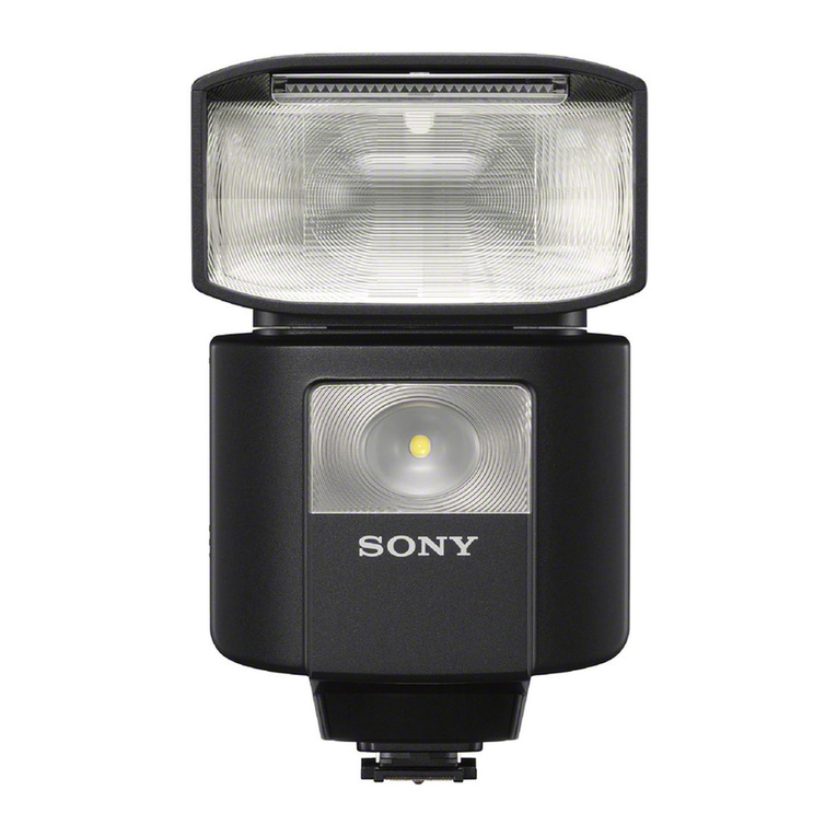
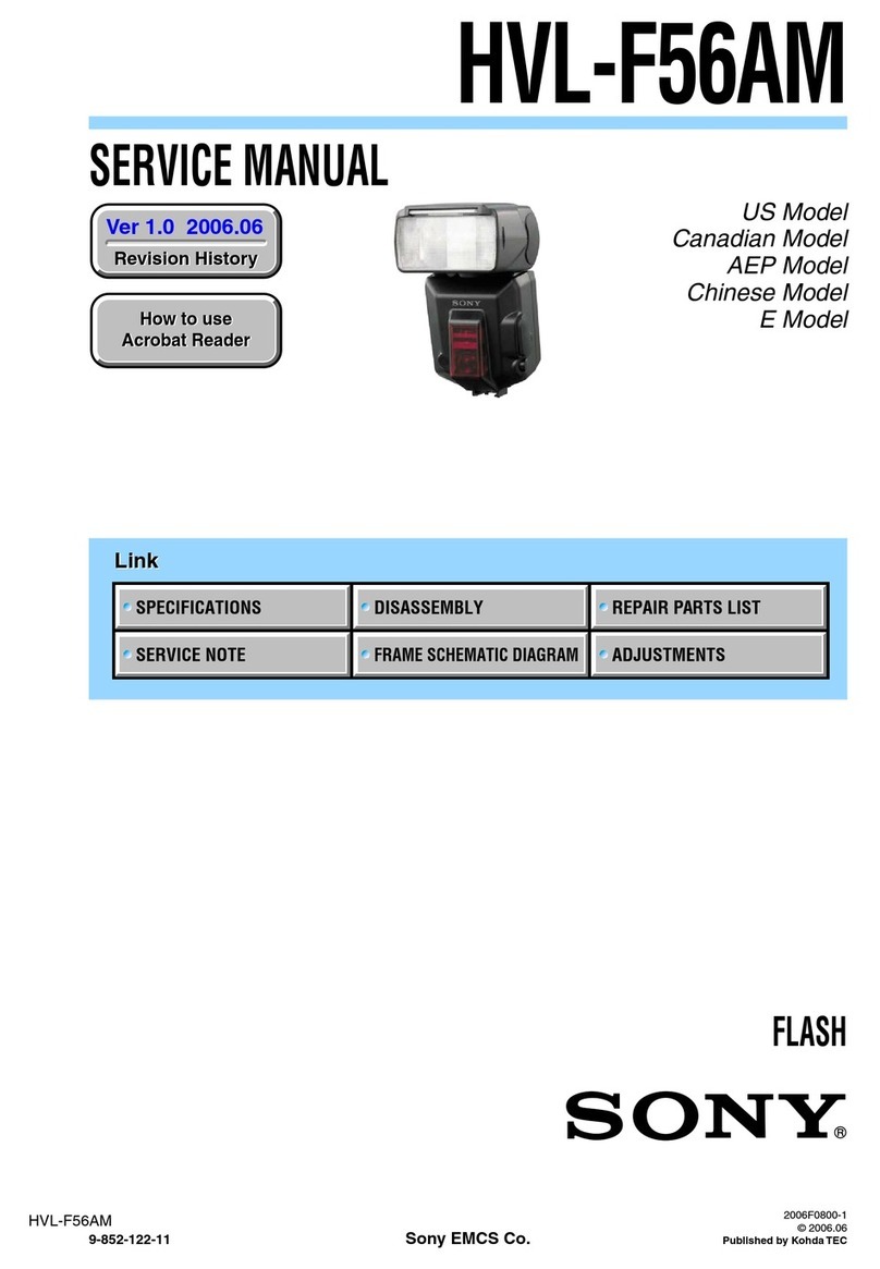
Sony HVL-F43M User manual

SERVICE MANUAL
Sony Corporation
Published by Sony Techno Create Corporation
HVL-F43M
SPECIFICATIONS
FLASH
9-893-749-01
2013E33-1
© 2013.05
US Model
Canadian Model
AEP Model
UK Model
E Model
Chinese Model
Ver. 1.0 2013.05
Guide number
Normal flash (ISO100)
Manual flash/35mm-format
APS-C format
Power level Flash coverage setting (mm)
15*24 28 35 50 70 105
1/1 13232425303543
1/2 9.2 16.3 17.0 17.7 21.2 24.7 30.4
1/4 6.5 11.5 12.0 12.5 15.0 17.5 21.5
1/8 4.6 8.1 8.5 8.8 10.6 12.4 15.2
1/16 3.3 5.8 6.0 6.3 7.5 8.8 10.8
1/32 2.3 4.1 4.2 4.4 5.3 6.2 7.6
1/64 1.6 2.9 3.0 3.1 3.8 4.4 5.4
1/128 1.1 2.0 2.1 2.2 2.7 3.1 3.8
*When the wide panel is attached.
Power level Flash coverage setting (mm)
15*24 28 35 50 70 105
1/1 13242530354143
1/2 9.2 17.0 17.7 21.2 24.7 29.0 30.4
1/4 6.5 12.0 12.5 15.0 17.5 20.5 21.5
1/8 4.6 8.5 8.8 10.6 12.4 14.5 15.2
1/16 3.3 6.0 6.3 7.5 8.8 10.3 10.8
1/32 2.3 4.2 4.4 5.3 6.2 7.2 7.6
1/64 1.6 3.0 3.1 3.8 4.4 5.1 5.4
1/128 1.1 2.1 2.2 2.7 3.1 3.6 3.8
*When the wide panel is attached.
HSS flat flash (ISO100)
Manual flash/35mm-format
APS-C format
Frequency/Repetition
s2epetition is the approximate number of times that are possible
before a new battery is completely dead.
Shutter speed Flash coverage setting (mm)
15*24 28 35 50 70 105
1/250 5.0 8.4 9.1 9.9 10.8 14.0 16.7
1/500 3.5 5.9 6.4 7.0 7.7 9.9 11.8
1/1000 2.5 4.2 4.6 5.0 5.4 7.0 8.4
1/2000 1.8 3.0 3.2 3.5 3.8 5.0 5.9
1/4000 1.2 2.1 2.3 2.5 2.7 3.5 4.2
1/8000 0.9 1.5 1.6 1.8 1.9 2.5 3.0
1/12000 0.6 1.0 1.1 1.2 1.4 1.8 2.1
*When the wide panel is attached.
Shutter speed Flash coverage setting (mm)
15*24 28 35 50 70 105
1/250 5.0 9.1 9.9 10.8 14.0 15.3 16.7
1/500 3.5 6.4 7.0 7.7 9.9 10.8 11.8
1/1000 2.5 4.6 5.0 5.4 7.0 7.7 8.4
1/2000 1.8 3.2 3.5 3.8 5.0 5.4 5.9
1/4000 1.2 2.3 2.5 2.7 3.5 3.8 4.2
1/8000 0.9 1.6 1.8 1.9 2.5 2.7 3.0
1/12000 0.6 1.1 1.2 1.4 1.8 1.9 2.1
*When the wide panel is attached.
Alkaline Nickel hydride
(2100 mAh)
Frequency (sec) Approx. 0.1 - 2.9 Approx. 0.1 - 2.2
2EPETITIOn (times) Approx. 200 or more Approx. 250 or more
Functions in these operating instructions depend on testing conditions at our firm.
Design and specifications are subject to change without notice.
Trademark
“Multi Interface Shoe” is a trademark of Son
y
Corporation.
Continuous flash
performance
40 flashes at 10 flashes per second
(Normal flash, light level 1/32, 105 mm, nickel-metal
hydride battery)
AF illuminator Autoflash at low contrast and low brightness
Operating range (with a MMLENSATTACHEDTO$3,2
A700)
Central area: 0.5 m to 6 m
Peripheral areas : 0.5 m to 3 m
Flash control Flash control using pre-flash (P-TTL/ADI)
LED light Center luminance
intensity: Approx. 400 lx at 0.5 m (1 feet
7 3/4 inches) or 100 lx at 1 m
(3 feet 3 3/8 inches)
Lighting distance: Approx. 1 m (3 feet 3/8 inches)
(When recording movies, set to
ISO 3200 & F5.6)
Focal length supported: 35 mm (35 mm format
angle of view)
Continuous lighting Approx. 4 hours (using
time: AA alkaline batteries, at
center luminance
intensity)
Color temperature: Approx. 5,500K
Dimension
(Approx.)
75 mm × 140 mm × 87 mm (3 in. × 5 5/8 in. × 3 1/2 in.)
(w/h/d)
Mass (Approx.) 355 g (12 1/2 oz) (excluding the batteries)
Power requirements DC 6 V
2Ecommended
batteries
FoUR,2!!SIZEALKALIne batteries
Four AA-size rechargeable nickel-metal hydride batteries
Included items Flash unit (1), Connector protect cap (1), Mini-stand (1),
Carrying case (1), Set of printed documentation
FLEXIBLE CIRCUIT BOARD REPAIRING
• Keep the temperature of soldering iron around 350 °C during
repairing.
• Do not touch the soldering iron on the same conductor of the
circuit board (within 3 times).
• Be careful not to apply force on the conductor when soldering
or unsoldering.
HVL-F43M
2
ABOUT PACKING
When you assemble this unit, please install after checking that the
packing is not twisted.
OK NG
ABOUT REPAIRING THE BOARD
The mounted parts of this unit that have each board cannot ex-
change with single.
When each boards are defective, exchange the complete mounted
board or the part including the board.
NOTES ON WIRING
Make sure that the conductive side of a flexible board does not
have any stain or foreign materials.
Do not touch the conductive side of flexible boards with bare
hands.
Plug in a flexible board straight, fully into the connector until it
reaches the end inside. (Fig. 1, Fig. 2, Fig. 3)
OK
(The flexible board was plugged in straight
and completely)
NG
(The flexible board was plugged in
crooked.)
NG
(The flexible board was not plugged in
completely.)
Flexible
Board Flexible
Board
Connector Connector
Reference line
Flexible
Board
Connector Connector
Flexible
Board
Reference line
Connector Connector
Flexible
Board
Flexible
Board
Reference line
3.giF
2.giF
1.giF
SECTION 1
SERVICING NOTES
When opening the connector’s holder in direction A, do not open
it with excessive force.
Holder
Connector Flexible Board
A
A
When closing the connector’s holder, press it evenly while pushing
a flexible board in direction B.
Holder
Insulation side
Connector Flexible Board
B
Make sure that the flat cable and flexible board are not cracked or
bent at the contact end.
Do not apply excessive force to the gilded flexible board.
Cut and remove the part of gilt
which comes off at the point.
(Be careful or some
pieces of gilt may be left inside)
The proper way to disconnect a connector is to grab the connec-
tor instead of the wires. If you pull on the wires, they might be
broken.
The proper way to connect a connector is to grab the connector in-
stead of the wires. If you push on the wires, they might be broken.

HVL-F43M
3
DISCHARGING OF THE CHARGING CAPACITOR
When disassembling the unit, the electrical discharge is necessary
for the electric shock prevention.
Please discharge of residual voltage in the following way.
Preparing the Short Jig
Two small clips are attached to each end of a resistor of 1 k/1 W
(Part No. 1-215-869-11).
Wrap with insulating tape on contact part of both ends of the resis-
tor to prevent electrical shock.
Nȍ:UHVLVWRU
VPDOOFOLS VPDOOFOLS
:UDSLQVXODWLQJWDSH
Method 1
Refer to “SECTION 2. DISASSEMBLY” (page 4), remove the
side mold (A) assy.
Insert the short jig in two holes on left side, discharge by connect-
ing the inside board about 10 seconds.
– Rear view –
short jig
Method 2
Refer to “SECTION 2. DISASSEMBLY” (page 4), remove the
battery case block.
Connect the short jig to the connector terminals (refer to below
figure) for about 10 seconds.
short jig

HVL-F43M
4
SECTION 2
DISASSEMBLY
• This set can be disassembled in the order shown below.
2-1. DISASSEMBLY FLOW
Note: Follow the disassembly procedure in the numerical order given.
2-2. SHOE ASSY (SH1)
(Page 4)
SET
2-3. MAIN (E) BLOCK
(Page 5)
2-4. BATTERY CASE BLOCK
(Page 5)
2-6. SIDE MOLD (A) ASSY
(Page 7)
2-7. MAIN (B), FRESNEL LENS
(Page 8)
2-8. WIDE PANEL ASSY
(Page 8)
2-5. BATTERY LID ASSY
(Page 6)
– Bottom view –
1two tapping screw
s
(M2.0 u4.5)
1two tapping screws
(M2.0 u4.5)
2Remove the shoe
block in the direction
of an arrow.
3shoe flexible board
4flexible board
5shoe assy
(SH1)

HVL-F43M
5
2-4. BATTERY CASE BLOCK, CHARGING CAPACITOR ELECTRICAL DISCHARGE PROCESSING
2-3. MAIN (E) BLOCK
– Left view –
2two tapping screws
(M2.0 u4.5) 1Rotate the flash unit in the direction of
an arrow A, and set to the position
of 90°.
A
4Remove the main (E) block
in the direction of an arrow.
3Open the battery lid.
7main (E)
5connector
(8P)
6connector
(2P)
0etKRG Rf RSeQtKe EDtteU\ OiG
2tapping screw
(M2.0 u4.5)
2tapping screw
(M2.0 u4.5)
2tapping screw
(M2.0 u4.5)
3connector
(20P)
1connector
(3P)
:LUHVHWWLQJ
battery case block
–)URQWYLHZ–
'LVFKDJLQJRIWKHFKDJLQJFDSDFLWRU
4battery case block
Note: Connector to discharge is visible when
removing the battery case block.
Discharge the charging capacitor refer
to "DISCHARGING OF THE
CHARGING CAPACITOR" on page 3.

HVL-F43M
6
2-5. BATTERY LID ASSY
A
B
1shaft
2spring
3battery lid assy
1Insert the shorter end of
the spring in the hole.
2Rotate the longer end of the spring
by 90° in the direction of an arrow.
3While rotating spring by 90° in the direction of
arrow
A
, orient the longer end of the spring
in the direction of arrow
B
.
4Insert the longer end of the
spring in the hole of the
battery lid assy.
5Fix the battery lid assy and the
spring by threading the shaft.
battery lid assy
0HWKRGIRULQVWDOOLQJWKHEDWWHU\OLGDVV\
battery case
hole
hole
–ERWWRPOHIWYLHZ–

HVL-F43M
7
2-6. SIDE MOLD (A) ASSY, CHARGING CAPACITOR ELECTRICAL DISCHARGE PROCESSING
1Pour alcohol around the side mold
(A) to weaken the adhesion of the
side mold tape.
3side mold tape
3side mold tape
hole
hole
hole
hole boss
boss
2Insert the tip of the tweezers in
the slit of side mold (A) assy and
scoop them.
4side mold (A) assy
Note 1: When installing the side mold (A) assy,
align the boss with the hole.
4side mold (A) assy
Note 1: When installing the side mold (A) assy,
align the boss with the hole.
Note 2: Two holes to discharge is visible when
removing this side mold assy.
Discharge the charging capacitor refer to
"DISCHARGING OF THE CHARGING
CAPACITOR" on page 3.
– Rear view –
'iVFKaJiQJ RI WKe FKaJiQJ FaSaFiWRr

HVL-F43M
8
2-8. WIDE PANEL ASSY
2-7. MAIN (B), FRESNEL LENS
1two tapping screws
(M2.0 u4.5)
3main cover
2two claws
4catch sheet
5wide panel assy
2two tapping screws
(M2.0 u4.5) 2two tapping screws
(M2.0 u4.5)
2two tapping screws
(M2.0 u4.5)
3two claws
3claw 6main (B)
main (B)
flash unit
4Remove the main
(B) block in the
direction of an
arrow.
5two silicon washers
silicon washers
– Upper view –
A
&DXWiRQ IRr iQVWDOOiQJ WKe PDiQ%
7acrylic panel
Note 2: Be careful not to pollute,
such as fingerprints.
7acrylic panel
Note 2: Be careful not to pollute,
such as fingerprints.
1Rotate the main (E) block in
the direction of an arrow A,
and set the flash unit to the
position of 90°.
Note 1: When installing the main (B), confirm that
silicon washers are present at the two locations
specified in the figure.

9
HVL-F43M
SECTION 3
EXPLODED VIEWS
1 4-000-746-01 SCREW (M2.0X4.5), TAPPING
MA1 X-2587-731-1 MAIN SUB ASSY
SH1 X-2587-730-1 SHOE ASSY
Ref. No. Part No. Description Remark Ref. No. Part No. Description Remark
Note:
• -XX and -X mean standardized parts, so
they may have some difference from the
original one.
• Items marked “*” are not stocked since
they are seldom required for routine ser-
vice. Some delay should be anticipated
when ordering these items.
• The mechanical parts with no reference
number in the exploded views are not sup-
plied.
• Color Indication of Appearance Parts Ex-
ample:
KNOB, BALANCE (WHITE) . . . (RED)
Parts Color Cabinet’s Color
3-1. OVERALL SECTION
battery case section
1
1
11
1
1
not supplied
MA1
SH1

10
HVL-F43M
3-2. BATTERY CASE SECTION
51 X-2581-774-1 LID ASSY, BATTERY 52 4-000-746-01 SCREW (M2.0X4.5), TAPPING
Ref. No. Part No. Description Remark Ref. No. Part No. Description Remark
52
52
51
not supplied
not supplied
not
supplied
flash unit section
52
A
A

11
HVL-F43M
3-3. FLASH UNIT SECTION
101 X-2581-777-2 PANEL ASSY, WIDE
102 X-2581-775-1 MOLD (A) ASSY, SIDE
103 4-288-990-01 TAPE, SIDE MOLD
104 4-000-746-01 SCREW (M2.0X4.5), TAPPING
Ref. No. Part No. Description Remark Ref. No. Part No. Description Remark
101
104
102
103
104
104
104
104
102
103
104
104
104
not supplied
not supplied
not supplied
not supplied
not supplied
not supplied
not supplied
not supplied

Ref. No. Part No. Description Remark
HVL-F43M
12
SECTION 4
ACCESSORIES
4-438-404-01 SHOE COVER (Connector protect cap)
4-463-175-11 MANUAL, INSTRUCTION
(ENGLISH, FRENCH) (EXCEPT CH)
*4-463-175-21 MANUAL, INSTRUCTION
(GERMAN, ITALIAN, DUTCH) (CEA)
*4-463-175-31 MANUAL, INSTRUCTION (SPANISH, SWEDISH,
PORTUGUESE, GREEK) (CEC)
*4-463-175-41 MANUAL, INSTRUCTION (SLOVAKIAN,
HUNGARIAN, ROMANIAN, POLISH) (CEC)
*4-463-175-51 MANUAL, INSTRUCTION
(RUSSIAN, DANISH, CZECH, FINNISH) (CEC)
4-463-175-61 MANUAL, INSTRUCTION
(TRADITIONAL CHINESE, KOREAN, ARABIC)
(E17)
*4-463-175-71 MANUAL, INSTRUCTION
(SIMPLIFIED CHINESE) (CH)
*4-465-852-01 CASE, FLASH (Carrying case)
501 X-2585-465-1 MINI STAND (Mini-stand)
501
Mini-stand (1)
• Items marked “*” are not stocked since
they are seldom required for routine ser-
vice. Some delay should be anticipated
when ordering these items.
• Abbreviation
CEA : Mainly UK, French, German,
Dutch and Italian models
CEC : Except UK, French, German,
Dutch and Italian in European
models
CH : Chinese model
E17 : Asian model

MEMO
HVL-F43M
13

HVL-F43M
REVISION HISTORY
Checking the version allows you to jump to the revised page.
Also, clicking the version at the top of the revised page allows you to jump to the next revised page.
Ver. Date Description of Revision
1.0 2013.05 New
Other manuals for HVL-F43M
2
Table of contents
Other Sony Flashlight manuals
Popular Flashlight manuals by other brands

Pfannenberg
Pfannenberg Quadro-A-DMX Operating and installation instruction

Eurotops
Eurotops P429E user manual

RovyVon
RovyVon Angel Eyes E300S user manual

Harbor Freight Tools
Harbor Freight Tools 91033 Assembly and operating instructions

Milwaukee
Milwaukee M18 UBL Operator's manual

Asaklitt
Asaklitt MF-H03 quick start guide