Sony BSS-100 User manual

SMS STANDARD PACKAGE
BSS-100
Serial No. 10001 and Higher
1st Edition (Revised 2)
INSTALLATION MANUAL Japanese/English
電気製品は、安全のための注意事項を守らないと、火災
や人身事故になることがあり、危険です。
このインストレーションマニュアルには、事故を防ぐための重要な注意事項
と製品の取り扱いかたを示してあります。このインストレーションマニュア
ルをよくお読みのうえ、製品を安全にお使いください。お読みになったあと
は、いつでも見られるところに必ず保管してください。
警告

2(J)
ソニー製品は安全に十分に配慮して設計されています。しかし、電気製品は
まちがった使い方をすると、火災や感電などにより死亡や大けがなど人身事
故につながることがあり、危険です。
事故を防ぐために次のことを必ずお守りください。
インストール前のご注意
この製品をQL-50以外のQuarterLシリーズまたは他社製PC (パーソナルコ
ンピューター) にインストールする際には、PC の種類によっては基板ス
ロットの物理的な制約およびPC側の電源部の容量不足に起因する発熱・発
火の可能性により、インストールできないものもありますので、事前にソ
ニーのサービス担当者または営業担当者にお問い合わせください。
安全のための注意事項を守る
4 (J) ページの注意事項をよくお読みください。
故障したら使用を中止する
ソニーのサービス担当者または営業担当者にご連絡ください。
万一、異常が起きたら
安全のために
警告表示の意味
このインストレーションマニュ
アルおよび製品では、次のよう
な表示をしています。表示の内
容をよく理解してから本文をお
読みください。
警告
この表示の注意事項を守らない
と、火災や感電などにより死亡
や大けがなど人身事故につなが
ることがあります。
注意
この表示の注意事項を守らない
と、感電やその他の事故により
けがをしたり周辺の物品に損害
を与えたりすることがあります。
注意を促す記号
行為を禁止する記号
行為を指示する記号
すぐに電源を切り、消火する。
/
火災 感電
注意
禁止
プラグをコン
セントから抜く
炎が出たら

3(J)
目次
警告 ......................................................................................................................4 (J)
注意 ......................................................................................................................4 (J)
概要 ...........................................................................................................................5 (J)
準備 ...........................................................................................................................6 (J)
必要なソフトウェア..........................................................................................6 (J)
PCの機種選定に際して....................................................................................6 (J)
基板をインストールする前に..........................................................................6 (J)
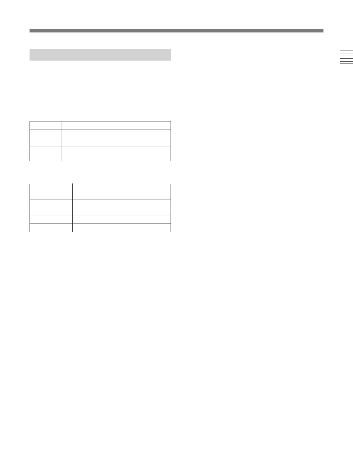
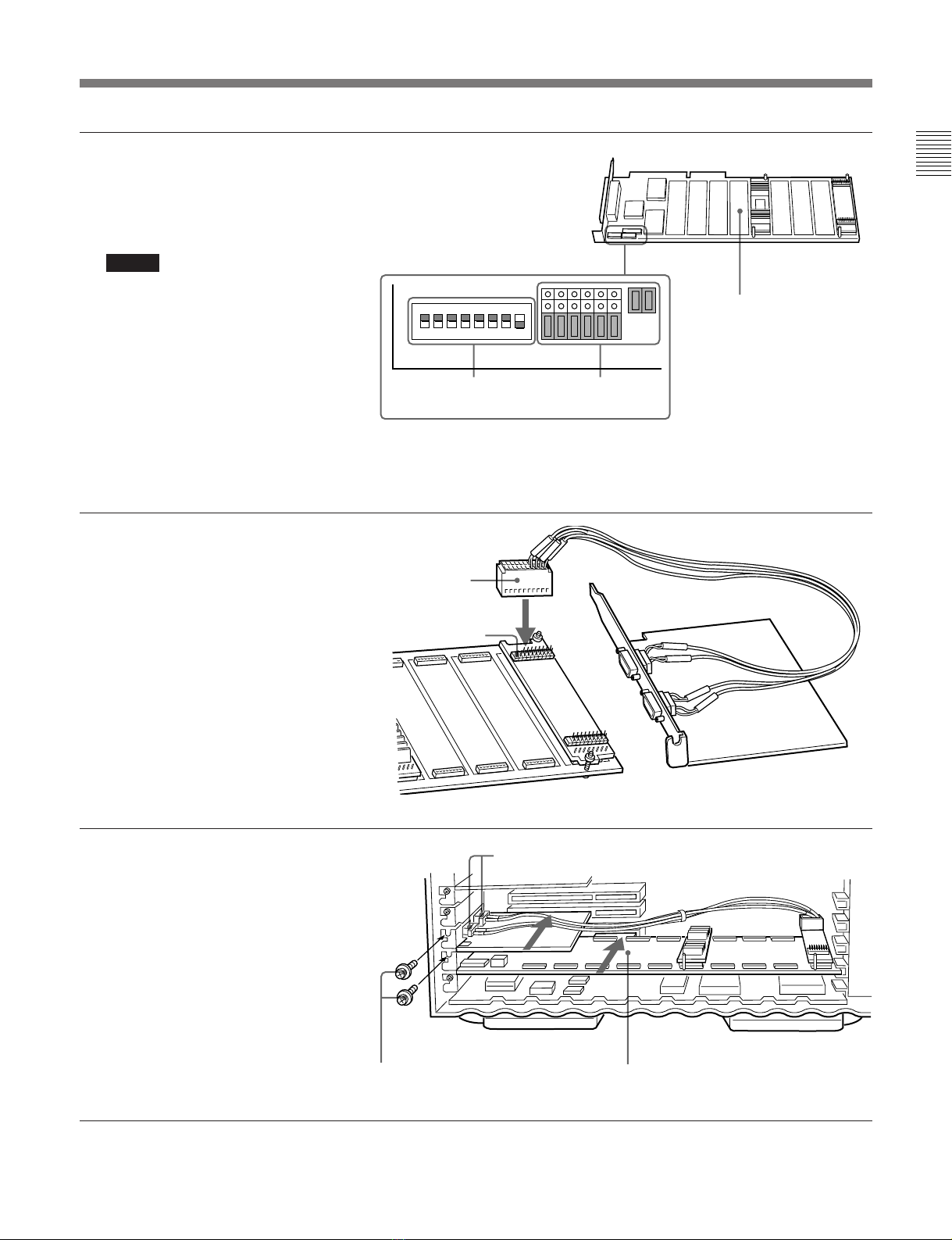
DIPスイッチの設定 ..........................................................................................7 (J)
基板のインストール.................................................................................................8 (J)
各部の名称と働き ................................................................................................. 10 (J)
仕様 ........................................................................................................................ 10 (J)
日
本
語
・Microsoft、WindowsNT、SQLServer は、米国 MicrosoftCorporation の
登録商標または商標です。
・IBM は米国 InternationalBusinessMachines,Inc.の登録商標です。
・Pentium は、米国 IntelCorporation の登録商標です。
・その他、記載されているすべての会社名、製品名は一般に各社の登録商標
または商標です。
権利者の許諾を得ることなく、このソフトウェアおよび取扱説明書の内容の
全部または一部を複写すること、およびこのソフトウェアを賃貸に使用する
ことは、著作権法上禁止されております。
ソフトウェアを使用したことによるお客様の損害、または第三者からのいか
なる請求についても、当社は一切その責任を負い兼ねます。
万一、製造上の原因による不良がありましたらお取り替えいたします。それ
以外の責はご容赦ください。
このソフトウェアは、指定された装置および目的以外には使用できません。
このソフトウェアの仕様は、改良のため予告なく変更することがあります
が、ご了承ください。
この装置は、 情報処理装置等電波障害自主規制協議会(VCCI)の基準に
基づく第一種情報技術装置です。この装置を家庭環境で使用すると電波妨
害を引き起こすことがあります。この場合には使用者が適切な対策を講ず
るよう要求されることがあります。

4(J)
基板を改造しない
基板を改造すると火災の原因となります。
調整や設定および点検を行う必要がある場合は、ソニーのサービス担当者ま
たは営業担当者にご依頼ください。
基板をPCにインストールするときは、PCの電源プラグをコ
ンセントから抜く
電源プラグをコンセントに接続したまま基板のインストールを行うと、感電
の原因となります。
下記の注意を守らないと、
火災や感電により死亡や大けがにつながることがあります。
感電火災
警告
プラグをコン
セントから抜く
禁止
基板をPCにインストールするときは、PC内部の鋭利な部品
でけがをしないように注意する
PC内部に不用意に手を入れると、鋭利な部品に指などを引っかけて思わぬ
けがをすることがあります。
下記の注意を守らないと、
けがをしたり周辺の物品に損害を与えることがあります。
注意
注意

5 (J)
概要
BSS-100は本インストレーションマニュアルおよび、以下の構成品に
よって構成されています。これらはいずれもホストコンピューター
(以下、PCと称します) にインストールし、IDC(IntelligentDevice
Controller)とアプリケーションシステムとのインターフェースや、
ファイル情報の管理などに使用します。
•IDCインターフェースボード
IDCと通信するための基板です。
•IDC接続用端子
IDCインターフェースボードとIDCを接続するために使用します。
•オペレーティングプログラムディスク
SMS(ServerManagementSystem) 制御用ソフトウェアが入って
います。
本マニュアルでは、これらの基板や端子のインストール のし か たを
説明します。
なお、本マニュアルの説明は、ホストコンピューターとしてソニー
QL-50を使用しているという想定に基づいています。

6 (J)
必要なソフトウェア
BSS-100をインストールするには以下のソフトウェアが必要です。
•MicrosoftWindowsNTServer3.51または4.0 (日本語版)
•MicrosoftSQLServer6.5 (日本語版)
または
•MicrosoftWindowsNTServer3.51または4.0 (英語版)
•MicrosoftSQLServer6.5 (英語版)
PCの機種選定に際して
BSS-100をご使用になるには、フルサイズのATバスの基板 (IDC
インターフェースボード)とハーフサイズのATバスの基板 (IDC接
続用端子付き基板) をPCにインストールします。PCとしてソニー
QL-50以外のIBMPC互換機をご使用になる場合、これらの基板
をPCにインストー ル できな いことがあります 。PCの機種選定に際し
ては、次表の条件をご考慮ください。
PC選定のための項目別条件
準備
基板をインストールする前に
PCのIDCインターフェースボード用のI/Oアドレスおよび 割り込 み
チャンネルを使用可能にします。
PCがソニーQL-50、IDCインターフェースボード用のI/Oアドレスが
150h、割り込みチャンネルが5 (いずれも出荷時の設定) の場合、
以下のように設定します。
1BIOSUtilityを起動する。
2PCIシステムの設定をAutoにする。
3ISA (非 PnPタイプ) カードの設定で、IRQ5とI/Oポートの
150〜15Fを、それぞれYESに設定する。
◆ PCがソニーQL-50以外の場合は、PCまたはPCに実装されている
拡張基板に付属の説明書を参照して設定してください。
4WindowsNTをインストール する。
5WindowsNTを起動して、WindowsNT診断プログラム
winmsd.exeにより、I/Oアドレス150hと割り込みチャンネル5
が使用可能であることを確認する。
出荷時設定I/Oアドレス、割り込みチャンネルを使用可能状
態にできない場合は
何らかの理由により、出荷時設定のI/Oアドレスと割り込 み チャン
ネルを使用可能状態にできない場合は、別のI/Oアドレスと割り込
みチャンネルを指定してください。
I/OアドレスはDIPスイッチにより変更します。割り込みアドレスを
変更するには、ソフトウェアインストール 時 にレジストリの指 定を変 更
します。
これらの設定の変更に際しては、次表および次項「DIPスイッチの
設定」を参照してください。
基板別I/Oアドレス、割り込みチャンネル設定情報
ご注意
出荷時設定を変更したI/Oアドレス、出荷時設定を変更して新た
に設定したい割り込みチャンネルは、メモしておいてください。ソフ
トウェアをインストールするときに必要になります。
項目
PC
CPU
メモリー
ハードディスクドライブ
EthernetI/F
空きATバススロット
IDCインターフェースボー
ド用空きI/Oアドレス
推奨条件
ソニーQL-50
IntelPentium
90以上
64Mバイト
―
―
―
150h
必要 (最低)条件
IBMPC互換機
IntelPentium
32Mバイト
1Gバイト
WindowsNT3.51でサ
ポートされていること
フルサイズ×1、ハーフサ
イズ× 1
150h、200h、300hのいず
れかの16バイト
IDCインターフェースボー
ド用空き割り込みチャン
ネル
3、5、11、15のいずれか 5
その他 モニター、キーボード、マ
ウスなどは、Windows
NTの操作に使用できる
ものであること。
―
基板名称 設定項目 設定方法 設定範囲 出荷時設定
IDCインター
フェースボー
ド
I/Oアドレス
(16バイト) DIPスイッチ
(SW1) 150h、200h、
300h 150h
割り込み
チャンネル レジストリ指
定3、5、11、15 5

7 (J)
DIPスイッチの設定
IDCインターフェースボード上のDIPスイッチSW1により、それぞれ
のボード用のI/Oアドレスを設定します。
◆各DIPスイッチの位置については、「基板のインストール 」(8 (J) ページ)
をご覧ください。
SW1の設定
SW1によるIDCインターフェースボード用I/Oアドレスの設定
スイッチNo. 機能 出荷時設定 備考
1 I/Oアドレス設定 ON 次表参照。
2 I/Oアドレス設定 OFF
3〜8 使用しません。 OFF OFFにして
おきます。
SW1のスイッチ
No.1の設定 SW1のスイッチ
No.2の設定 I/Oアドレス
ON ON ―
ON OFF 150h
OFF ON 200h
OFF OFF 300h

8 (J)
基板のインストール
基板を改造しない
基板を改造すると火災の原因となります。
調整や設定および点検を行う必要がある場合は、ソニーのサービス担当者または営業担当
者にご依頼ください。
基板をPCにインストールするときは、PCの電源プラグをコンセントから抜く
電源プラグをコンセントに接続したまま基板のインストールを行うと、感電の原因となります。
基板をPCにインストールするときは、PC内部の鋭利な部品でけがをしないよう
に注意する
PC内部に不用意に手を入れると、鋭利な部品に指などを引っかけて思わぬけがをするこ
とがあります。
警告
注意
1PCの電源を切った後、左右のカバー
ロックを指で手前に引いたまま、カ
バーを引き出す。
ここでは、PCとしてソニーQL-50を使用する場合を例として、基板
のインストールのしかたを説明します。
他のPCをお使いの場合は、以下の手順を参考にして基板をインス
トー ルし てください。
ご注意
基板のインストー ルに 際し ては 、PC内部の配線を無用に引いたり、
押したりしないようにしてください。
PC カバー カバーロック
禁止
プラグをコン
セントから抜く
注意

9 (J)
12345678
ON RLCO A D F 0 8
2IDCインターフェースボード上のジャン
クションポストおよびDIPスイッチSW1
が右図のように設定されていることを
確認する。
ご注意
•IDCインターフェースボード上の出荷
時設定I/Oアドレスを変 更した場 合
は、SW1のスイッチ1と2の設定は右
図と異なります。
•IDCインターフェースボードに貼付し
てある予備ネジは、はがさないでく
ださい。保守や修理の際に止めネジ
が破損したり紛失したりした場合に
必要になります。
3IDC接続用20ピン端子を、IDCイン
ターフェースボードのCN1端子に接続
する。
(IDC接続用20ピン端子は、必ず右
のイラストと同じ向きにしてください。)
4IDCインターフェースボードを下から2
番目のスロットに、また、IDC接続用
D-sub9ピン端子2個 (プレート付き)
を下から3番目のスロットに挿入して、
いずれもネジ止めする。
IDCインターフェース
ボード
ジャンクションポスト
DIPスイッチSW1
(出荷時設定の場合)
CN1端子
IDC接続用
20ピン端子
IDC接続用D-sub 9ピン端子
止めネジ IDCインターフェースボード
SLOT2
SLOT6
SLOT5

10 (J)
各部の名称と働き
IDC端子 (D-sub 9ピン×2)
RS-422A対応の出力端子です。IDC
(IntelligentDeviceController) に接続
します。
環境条件
動作温度:10℃〜35℃
動作湿度:30〜70% (ただし、結露のないこと)
保存温度:0℃〜60℃
保存湿度:20〜90% (ただし、結露のないこと)
寸法
(最大突起部含む。ケーブル含まず。)
電源
バス形式およびサイズ
IDCインターフェースボード:ATバスフルサイズ
IDC接続用端子:ATバスハーフサイズ
仕様および外観は、改良のため予告なく変更することがありますが、ご了承ください。
仕様
IDC接続用端子 IDCインターフェースボード
幅約118mm 約354mm
奥行き 約121mm 約126mm
高さ 約23mm 約23mm
IDC接続用端子 IDCインターフェースボード
電圧 − 5+0.25V
電流 − 標準1.8A

1(E)
WARNING
To prevent fire or shock hazard, do not
expose the unit to rain or moisture.
To avoid electrical shock, do not open the
cabinet. Refer servicing to qualified
personnel only.
VORSICHT
Um Feuergefahr und die Gefahr eines elektrischen
Schlages zu vermeiden, darf das Gerät weder Regen noch
Feuchtigkeit ausgesetzt werden.
Um einen elektrischen Schlag zu vermeiden, darf das
Gehäuse nicht geöffnet werden. Überlassen Sie
Wartungsarbeiten stets nur einem Fachmann.
For the customers in USA
This equipment has been tested and found to comply with
the limits for a Class A digital device, pursuant to Part 15
of the FCC Rules. These limits are designed to provide
reasonable protection against harmful interference when
the equipment is operated in a commercial environment.
This equipment generates, uses, and can radiate radio
frequency energy and, if not installed and used in
accordance with the instruction manual, may cause
harmful interference to radio communications. Operation
of this equipment in a residential area is likely to cause
harmful interference in which case the user will be
required to correct the interference at his own expense.
You are cautioned that any changes or modifications not
expressly approved in this manual could void your
authority to operate this equipment.
The shielded interface cable recommended in this manual
must be used with this equipment in order to comply with
the limits for a digital device pursuant to Subpart B of Part
15 of FCC Rules.
This symbol is intended to alert the user to
the presence of important operating and
maintenance (servicing) instructions in the
literature accompanying the appliance.
WARNING: THIS WARNING IS APPLICABLE FOR USA
ONLY.
If used in USA, use the UL LISTED power cord specified
below.
DO NOT USE ANY OTHER POWER CORD.
Plug Cap Parallel blade with ground pin
(NEMA 5-15P Configuration)
Cord Type SJT, three 16 or 18 AWG wires
Length Less than 2.5 m (8 ft 3 in)
Rating Minimum 10 A, 125 V
WARNING: Using this unit at a voltage other than 120V
may require the use of a different line cord or
attachment plug, or both. To reduce the risk
of fire or electric shock, refer servicing to
qualified service personnel.
For the customers in the United Kingdom
WARNING
THIS APPARATUS MUST BE EARTHED.
IMPORTANT
The wires in this mains lead are coloured in accordance
with the following code:
Green-and-yellow: Earth
Blue: Neutral
Brown: Live
As the colours of the wires in the mains lead of this
apparatus may not correspond with the coloured markings
identifying the terminals in your plug proceed as follows:
The wire which is coloured green-and-yellow must be
connected to the terminal in the plug which is marked by
the letter E or by the safety earth symbol Yor coloured
green or green-and-yellow.
The wire which is coloured blue must be connected to the
terminal which is marked with the letter N or coloured
black.
The wire which is coloured brown must be connected to
the terminal which is marked with the letter L or coloured
red.
English

2(E)
For the customers in Europe
WARNING
This is a Class A product. In a domestic environment, this
product may cause radio interference in which case the
user may be required to take adequate measures.
Pour les utilisateurs en Europe
AVERTISSEMENT
Il s’agit d’un produit de Classe A. Dans un environnement
domestique, cet appareil peut provoquer des
interférences radio, dans ce cas l’utilisateur peut être
amené à prendre des mesures appropriées.
Per gli acquirenti in Europa
ATTENZIONE
Questo è un apparecchio di classe A e come tale, in un
ambiente domestico, può causare interferenze radio.
É necessario quindi che l’utilizzatore adotti gli
accorgimenti adeguati.
Para los clientes de Europa
ADVERTENCIA
Éste es un producto de clase A. En un ambiente
doméstico, este producto puede causar interferencias
radioeléctricas, en cuyo caso el usuario puede tener que
tomar las medidas adecuadas.
Für Kunden in Europa
Warnung
Dies ist eine Einrichtung, welche die Funk-Entstörung
nach Klasse A besitzt. Diese Einrichtung kann im
Wohnbereich Funkstörungen verursachen; in diesem Fall
kann vom Betreiber verlangt werden, angemessene
Maßnahmen durchzuführen und dafür aufzukommen.
Für Kunden in Deutschland
Dieses Produkt kann im kommerziellen und in
begrenztem Maße auch im industriellen Bereich
eingesetzt werden.
Attention – when the product is installed in rack:
1. Prevention against overloading of branch circuit
When this product is installed in a rack and is supplied
power from an outlet on the rack, please make sure
that the rack does not overload the supply circuit.
2. Providing protective earth
When this product is installed in a rack and is supplied
power from an outlet on the rack, please confirm that
the outlet is provided with a suitable protective earth
connection.
3. Internal air ambient temperature of the rack
When this product is installed in a rack, please make
sure that the internal air ambient temperature of the
rack is within the specified limit of this product.
4. Prevention against achieving hazardous condition
due to uneven mechanical loading
When this product is installed in a rack, please make
sure that the rack does not achieve hazardous
condition due to uneven mechanical loading.
• Microsoft, Windows NT and SQL Server are registered
trademarks or trademarks of Microsoft Corporation.
• IBM is a registered trademark of International Business
Machines, Inc.
• Pentium is a trademark of Intel Corporation.
• Other company and product names are trade marks of their
respective owners, whether registered or not.
NOTICE TO USERS
© 1996 Sony Corporation. All rights reserved. This manual
or the software described herein, in whole or in part, may not
be reproduced, translated or reduced to any machine
readable form without prior written approval from Sony
Corporation.
SONY CORPORATION PROVIDES NO WARRANTY WITH
REGARD THIS MANUAL, THE SOFTWARE OR OTHER
INFORMATION CONTAINED HEREIN AND HEREBY
EXPRESSLY DISCLAIMS ANY IMPLIED WARRANTIES OF
MERCHANTABILITY OR FITNESS FOR ANY PARTICULAR
PURPOSE WITH REGARD TO THIS MANUAL, THE
SOFTWARE OR SUCH OTHER INFORMATION. IN NO
EVENT SHALL SONY CORPORATION BE LIABLE FOR
ANY INCIDENTAL, CONSEQUENTIAL OR SPECIAL
DAMAGES, WHETHER BASED ON TORT, CONTRACT,
OR OTHERWISE, ARISING OUT OF OR IN CONNECTION
WITH THIS MANUAL, THE SOFTWARE OR OTHER
INFORMATION CONTAINED HEREIN OR THE USE
THEREOF.
Sony Corporation reserves the right to make any
modification to this manual or the information contained
herein at any time without notice.
The software described herein may also be governed by the
terms of a separate user license agreement.

3(E)
Table of Contents
Precautions .......................................................................................... 4 (E)
Overview.............................................................................................. 4 (E)
Preparations ........................................................................................ 5 (E)
Required Software..........................................................................5 (E)
Selecting a Computer .....................................................................5 (E)
Before Installing the Boards...........................................................5 (E)
DIP Switch Settings........................................................................6 (E)
Installing the Boards .......................................................................... 7 (E)
Location and Function of Parts......................................................... 9 (E)
Specifications....................................................................................... 9 (E)

4(E)
Precautions
Do not modify the printed circuit boards
Modifying the printed circuit boards can cause fires.
If adjustment, setting, or testing is necessary, consult a
Sony service representative or sales representative.
When installing a board in the computer, first
disconnect the computer power supply from
the AC outlet
Installing a board in the computer without first
disconnecting the power supply plug from the AC
outlet can lead to electric shock.
When installing a board in the computer, be
careful to avoid injury from sharp components
within the computer
Inserting a hand carelessly into the computer can lead
to injury to fingers or other parts of the body from
sharp edges of internal components.
Overview
The BSS-100 SMS Standard Package consists of this
manual and the items listed below. These items are to
be installed in the host computer, which will be
referred to as the “computer” in this manual. Their
functions include interfacing between IDCs (Intelligent
Device Controllers) and application systems, and
enabling file information management.
•IDC interface board
Carries out communications between the computer
and IDCs.
•IDC connectors
Used to connect IDCs to the IDC interface board.
•Operating program disks
Contain the SMS (Server Management System)
control software.
This manual explains how to install these boards and
connectors in the computer based on the assumption
that the computer used is a Sony QL-50 unit.

5(E)
Required Software
Installing the BSS-100 requires the following
software:
•Microsoft Windows NT Server 3.51 or 4.0 (US
English)
•Microsoft SQL Server 6.5 (US English)
Selecting a Computer
To use the BSS-100 involves installing a full-size AT-
bus board (IDC interface board) and a half-size AT-
bus board (board with IDC connectors) in the
computer. If using an IBM-compatible computer other
than the Sony QL-50, check first that these boards can
be installed. The following table shows requirements
for the installation.
Requirements for the computer selected
Preparations
Before Installing the Boards
To enable I/O address 150h for the IDC interface
board, and interrupt channel 5 (factory default
settings), proceed as follows.
1Start the BIOS Utility.
2Set the PCI system setting to Auto.
3In the settings for ISA (non-plug-n-play) cards,
select “Yes” for each of IRQ5 and I/O ports 150 to
15F.
If the computer is not a Sony QL-50, refer to the
documentation supplied with the computer or with
expansion boards fitted in the computer.
4Install Windows NT.
5Start Windows NT, and use the Windows NT
diagnosis program winmsd.exe to check that I/O
address 150h and interrupt channel 5 are enabled.
When it is not possible to use the factory
default I/O address and interrupt channel
settings
If for any reason it is not possible to use the factory
default I/O address and interrupt channel settings, it
will be necessary to use different I/O address and
interrupt channel settings.
DIP switch settings control the I/O address. Changing
the interrupt address is done by setting in the Registry
while installing the software.
When making these changes, refer to the following
table and the next item “DIP Switch Settings”
I/O address and interrupt channel settings for each board
Note
If you change the I/O address or interrupt channel from
their factory default settings, make a separate note of
the new settings. These will be needed when installing
the software.
Item Minimum
requirement Recommended
Computer IBM PC compatible Sony QL-50
CPU Intel Pentium At least Intel
Pentium 90
Memory 32 Mbytes 64 Mbytes
Hard disk drive 1 Gbyte —
Ethernet interface Must be supported
by Windows NT
3.51.
—
Free AT-bus slots Full-size ×1; half-
size x1 —
Free I/O addresses
for IDC interface
board
16 bytes at any of
150h, 200h, or
300h
150h
Free interrupt
channel for IDC
interface board
Any of 3, 5, 11, and
15 5
Miscellaneous Monitor, keyboard,
mouse, etc. must
be capable of
operating under
Windows NT.
—Board
name Setting Method
of setting Setting
values Factory
default
IDC
interface
board
I/O
address
(16 bytes)
DIP
switches
(SW1)
150h,
200h,
300h
150h
Interrupt
channel Registry 3, 5, 11,
15 5

6(E)
DIP Switch Settings
DIP switch SW1 on the IDC interface board controls
the I/O address for the board.
For the positions of the DIP switch, see the section
“Installing the Boards” (page 7(E)).
SW1 settings
I/O address settings for IDC interface board using SW1
Switch
number Function Notes
1 See next table.
2 I/O address
3 to 8 Not used Leave in OFF position.
I/O address
Factory
default
ON
OFF
OFF
SW1 switch 1
setting SW1 switch 2
setting I/O address
ON ON —
ON OFF 150h
OFF ON 200h
OFF OFF 300h
Preparations

7(E)
Precautions
•Do not modify the printed circuit boards
Modifying the printed circuit boards can cause fires.
If adjustment, setting, or testing is necessary, consult
a Sony service representative or sales representative.
•When installing a board in the computer, first
disconnect the computer power supply from the
AC outlet
Installing a board in the computer without first
disconnecting the power supply plug from the AC
outlet can lead to electric shock.
•When installing a board in the computer, be
careful to avoid injury from sharp components
within the computer
Inserting a hand carelessly into the computer can lead
to injury to fingers or other parts of the body from
sharp edges of internal components.
Installing the Boards
Use the following procedure to install the component
boards of the BSS-100 in the computer (Sony QL-50).
If your computer is other than the Sony QL-50, install
the boards appropriately using the following procedure
as reference.
Note
When installing the boards, take care not to
unnecessarily strain or compress the wiring inside the
computer.
1With the computer powered off,
release the catches on both sides of
the computer housing cover with
fingers and slide the cover out.
Cover
Catches
Computer
(Continued)

8(E)
SLOT2
SLOT6
SLOT5
12345678
ON RLCO A D F 0 8
2Make sure the junction posts and
DIP switches SW1 on the IDC
interface board are set as shown in
the figure on the right.
Notes
•If the I/O address settings on the
IDC interface board have been
changed, the settings of DIP
switches 1 and 2 of SW1 will not
be as shown in the figure.
•Do not remove the spare screws
stuck to the IDC interface board.
These are needed during
maintenance and repair if
retaining screws are damaged or
lost.
3Connect the 20-pin IDC connector
to the CN1 connector on the IDC
interface board.
(Be sure to connect the 20-pin IDC
connector in the orientation shown
in the figure on the right.)
4Insert the IDC interface board into
the second lowest slot and the two
D-sub 9-pin IDC connectors
attached to a plate into the third
lowest slot, then fix them with
fixing screws.
IDC interface board
DIP switches SW1
(Default settings) Junction posts
20-pin IDC connector
CN1 connector
Installing the Boards
D-sub 9-pin IDC connectors
Fixing screws IDC interface board

9(E)
Environment
Operating temperature: 10 ºC to 35 ºC (50 ˚F to 95 ˚F )
Operating humidity: 30% to 70% (Condensation not allowed)
Storage temperature: 0 ºC to 60 ºC (32 ˚F to 140 ˚F )
Storage humidity: 20% to 90% (Condensation not allowed)
Dimensions
(Values are approximate including protrusions, excluding cables.)
Power Requirements
Bus type and size
IDC interface board: AT bus full-size
IDC connectors: AT bus half-size
Design and specifications are subject to change without notice.
Location and Function of Parts
IDC connectors (D-sub 9-pin x 2)
RS-422A compatible output connectors. Connect
these connectors to the IDC (Intelligent Device
Controller).
Specifications
IDC connectors IDC interface board
Width 118 mm (4 3/4inches) 354 mm (14 inches)
Depth 121 mm (4 7/8inches) 126 mm (5 inches)
Height 23 mm (29/32 inch) 23 mm (29/32 inch)
IDC connectors IDC interface board
Voltage — 5 + 0.25 V
Current — 1.8 A typical

Table of contents
Other Sony Headphones manuals

Sony
Sony MDR-RF885RK User manual

Sony
Sony MDR-IF240RK - Headphones - Binaural User manual

Sony
Sony XBA-3 User manual

Sony
Sony MDR-IF125RK User manual

Sony
Sony MDR-EX14AP User manual

Sony
Sony MDR-EX300LP User manual

Sony
Sony MDR-EX33LPGRN Owner's manual

Sony
Sony MDR-XB400iP User manual

Sony
Sony MDR-1R User manual

Sony
Sony MDR-IF140K User manual

Sony
Sony MDR-EX510SL User manual

Sony
Sony MDR-EX71SL User manual

Sony
Sony XBA-N3AP User manual

Sony
Sony MDR MDR 710LP User manual

Sony
Sony DR-BT1 User manual

Sony
Sony MDR-AS400iP User manual

Sony
Sony MDR-MA100 User manual

Sony
Sony MDR-ZX600 User manual

Sony
Sony DR-E10iP/PBLU User manual

Sony
Sony PS4 FORTNITE PRO User manual