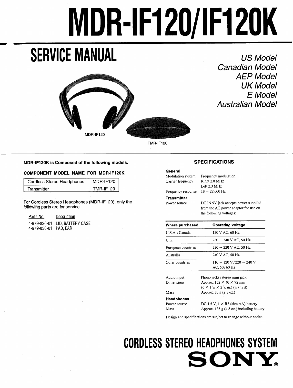
Sony MDR-IF120 User manual

MDR-IF120/1F120K
SERVICE
MANUAL
US
Model
Canadian
Model
AEP
Model
UK
Model
E
Model
Australian
Model
MDR-IF120
“oe
TMR-IF120
MDR-IF120K
is
Composed
of
the
following
models.
SPECIFICATIONS
COMPONENT
MODEL
NAME
FOR
MDR-IF120K
_
General
.
Modulation
system
Frequency
modulation
Cordless
Stereo
Headphones
MDR-IF120
Carrier
frequency
—
Right
2.8
MHz
|
Transmitter
|
TMR-IF
120
|
ie
330001
Transmitter
IMR-AF120
Frequency
response
18
—
22,000
Hz
Transmitter
For
Cordless
Stereo
Headphones
(MDR-IF120),
only
the
Power
source
DC
IN
9V
jack
accepts
power
supplied
following
parts
are
for
service.
’
from
the
AC
power
adaptor
for
use
on
wou
the
following
voltages:
Parts
No.
Description
eee
4-979-830-01
LID,
BATTERY
CASE
:
,
Where
purchased
Operating
voltage
4-979-838-01
PAD,
EAR
P
owes
U.S.A.
/Canada
120
V
AC,
60
Hz
U.K.
230
-
240
V
AC,
50
Hz
European
countries
220
-
230
V
AC,
50
Hz
Australia
240
V
AC,
50
Hz
Other
countries
110
—
120
V/220
~
240
V
AC,
50/60
Hz
Audio
input
Phono
jacks
/
stereo
mini
jack
Dimensions
Approx.
152
X
40
X
72
mm
(6X
1"
X
2%
in.)
(w/h/d)
Mass
Approx.
80
g
(2.8
02.)
Headphones
Power
source
DC
1.5
V,
1
X
R6
(size
AA)
battery
Mass
Approx.
135
g
(4.8
oz.)
including
battery
Design
and
specifications
are
subject
to
change
without
notice.
CORDLESS
STEREO
HEADPHONES
SYSTEM
SONY.

ae
eee
eres
2
If
your
AC
power
Setting
up
the
transmitter
1
Connect
the
transmitter
to
audio/video
equipment.
Select
one
of
the
hookups
below
depending
on
the
jack
type:
@
To
connect
to
LINE
OUT
or
REC
OUT
jacks
Transmitter
Connecting
cord
(supplied)
Left
{
}
channel
f}
fi
(white)
°
toLINEOUT
{66
or
REC
OUT
=
Stereo
system,
TV,
VCR,
etc.
(red)
®)
To
connect
toa
headphones
jack
Transmitter
y
Left
channel
(white)
Right
channel
(red)
Connecting
cord
(supplied)
mini
jack)
Unimatch
plug
|
adaptor
(not
to
a
headphones
supplied)
jack
(stereo
:
S
to
a
headphones
;
Discman,
jack
(stereo
WALKMAN,
TV,
phone
jack)
-
VCR,
etc.
SECTION
1
GENERAL
adaptor
is
equipped
with
a
voltage
selector,
before
connecting
the
AC
power
adaptor
to
an
AC
outlet,
set
it
to
the
operating
voltage
in
your
area
with
a
screw
driver.
AC
power
adaptor
(supplied)
220V=
240V
NOV
120V
.
Vf
faGE
s¥
{CTOR
3
Connect
the
transmitter
to
a
power
source.
Transmitter
==>
to
an
AC
outlet
to
DC
IN
9V
jack
AC
power
adaptor
(supplied)
Notes
*
Do
not
connect
to
the
AUDIO
IN
A
jacks
and
B
jack
at
the
same
time.
If
you
do
so,
the
audio
signals
may
be
mixed.
¢
Use
only
the
supplied
AC
power
adaptor.
Do
not
use
any
other
AC
power
adaptor.
i
~
“\@
Polarity
of
the
plug
¢
If
the
plug
of
the
AC
power
adaptor
does
not
fit
in
the
AC
outlet,
use
the
supplied
AC
plug
adaptor.
¢
When
you
connect
the
connecting
cord
directly
to
an
earphone
jack,
the
audio
signal
will
not
be
output
through
the
right
channel.
In
such
a
case,
use
the
separately
sold
PC-236HG
plug
adaptor.
*
WALKMAN
is
a
registered
trademark
of
Sony
Corporation,
This
section
is
extracted
from
instruction
manual.
a
a
Setting
up
the
headphones
1
Open
the
battery
compartment
lid
on
the
left
inner
side
of
the
headband.
2
insert
one
R6
(size
AA)
battery
by
matching
the
+
and
-
on
the
battery
to
the
+
and
—
in
the
battery
compartment.
3
Close
the
battery
compartment
lid.
Battery
life
Battery
Approx.
hours
Sony
alkaline
battery
100
AM3
(N)
Sony
battery
50
SUM-3
(NS)
When
to
replace
the
battery
Replace
the
battery
with
new
one
when
the
POWER
indicator
dims,
and
a
hissing
noise
increases.

i
RE
Eire
a
a
|
Listening
to
a
program
1
Turn
on
the
audio/video
equipment
connected
to
the
transmitter.
2
Turn
on
the
transmitter.
The
infrared
emitters
light
up.
3
Turn
on
the
power
of
the
headphones.
The
power
indicator
lights
in
red.
L
ie
yet
|
4
Put
on
the
headphones.
Mute
function
If
a
hissing
noise
is
heard
when
the
infrared
rays
are
obstructed,
or
the
headphones
are
used
outside
of
the
effective
range
(see
the
next
section),
the
mute
function
will
be
activated
and
the
sound
will
not
be
heard
from
the
headphones.
To
restore
the
sound,
move
nearer
toward
the
transmitter
or
remove
the
obstruction.
After
listening
to
a
program
Take
the
headphones
off
before
turning
off
the
headphones
and
the
transmitter.
Otherwise
you
may
hear
some
noise
when
the
infrared
rays
are
suddenly
cut
off.
Note
The
infrared
emitters
light
up
when
the
transmitter
is
turned
on.
The
brightness
of
the
emitters
may
not
be
uniform,
however,
this
is
nota
malfunction.
i
age
Hy
[ee
er
ee
eee
eae
eee
The
effective
areas
of
the
transmitter
The
illustration
below
shows
the
approximate
area
covered
by
the
infrared
rays
emitted
from
the
transmitter.
Transmitter
Infrared
ray
Approx.3m
2
(1187/,
yee
[\
>
a
euaaoe
(118'/,
in.)
Notes
¢
If
you
use
the
headphones
at
too
great
a
distance
from
the
transmitter,
you
may
hear
a
hissing
noise
and
if
there
is
an
object
between
the
receiver
and
the
transmitter,
the
sound
may
be
interrupted.
These
phenomena
are
inherent
to
infrared
ray.
communication
and
do
not
mean
that
there
is
a
problem
with
the
unit
itself.
¢
The
infrared
rays
will
not
penetrate
walls
or
opaque
glass,
therefore,
be
sure
to
stay
within
sight
of
the
transmitter.
¢
When
you
use
the
headphones
inside
the
area
illustrated
in
the
diagrams,
the
transmitter
can
be
placed
in
the
front,
behind
or
by
the
side
of
the
listener.
Se
a
eee
ee
ee
Precautions
¢
The
CE
mark
on
the
unit
is
valid
only
for
products
marketed
in
the
European
Union.
¢
When
the
headphones
is
not
to
be
used
for
a
long
period
of
time,
remove
the
battery
to
avoid
damage
caused
by
battery
leakage
and
subsequent
corrosion.
¢
When
the
transmitter
is
not
to
be
used
for
a
long
period
of
time,
disconnect
the
AC
power
adaptor
from
the
AC
outlet
holding
the
plug.
Do
not
pull
on
the
cord.
¢
Do
not
leave
the
cordless
stereo
headphones
system
in
a
location
subject
to
direct
sunlight,
heat
or
moisture.
¢
The
nameplate
indicating
operating
voltage,
power
consumption,
etc.,
is
located
on
the
bottom
of
the
AC
power
adaptor
(European
models
only).
Notes
on
headphones
Preventing
hearing
damage
Avoid
using
headphones
at
high
volume.
Hearing
experts
advise
against
continuous,
loud
and
extended
play.
If
you
experience
a
ringing
in
your
ears,
reduce
the
volume
or
discontinue
use.
Caring
for
others
Keep
the
volume
at
a
moderate
level.
This
will
allow
you
to
hear
outside
sounds
and
to
be
considerate
to
the
people
around
you.
If
you
have
any
questions
or
problems
concerning
the
system
that
are
not
covered
in
this
manual,
please
consult
the
nearest
Sony
dealer.
Be
sure
to
bring
the
headphones
and
the
transmitter
to
the
Sony
dealer
when
requiring
repair
work.
a=

SECTION
2
ELECTRICAL
ADJUSTMENTS
Note:
1.
The
adjustments
should
be
performed
in
the
order
given.
2.
The
adjustments
and
measurements
should
be
performed
for
both
L-ch
and
R-ch
unless
otherwise
indicated.
3.
L-ch
adjustment
should
be
completed
before
performing
R-ch
adjustment.
OSCILLATING
FREQUENCY
ADJUSTMENT
Connection:
frequency
counter
TX
board
TP
(CL54)
(L-ch)
es
TP
(CL04)
(R-ch)
<———p+
Adjustiment
procedure:
No
signal
state.
1.
Connect
the
frequency
counter
to
TP
(CL54)
(L-ch)
and
TP(CL04)
(R-ch).
2.
Adjust
with
L51
(L-ch)
and
LO1
(R-ch)
so
that
the
reading
on
the
frequency
counter
becomes
the
specified
value.
Specified
Value:
L-ch
L51
2.3MHz+2kHz
R-ch
LO1
2.8MHz+2kHz
Connection
and
Adjustment
Location
OSCILLATING
FREQUENCY
adjustment
LO1
(R-ch)
L51
(L-ch)
-TX
board
—
(Conductor
side)
regulated
dc
power
supply
9
Ls
7
PL

MDR-IF120/IF
120K
SECTION
3
DIAGRAMS
¢
Semiconductor
3-1.
PRINTED
WIRING
BOARD
(INFRARED
EMITTER)
Location
Ref.
No.
|
Location
Note:
*
o——
‘parts
extracted
from
the
component
side.
¢
[
_
:
indicates
side
identified
with
part
number.
:
Pattern
from
the
side
which
enables
seeing.

MDR-IF120/IF
120K
3-2.
SCHEMATIC
DIAGRAM
1
2
3
4
5
6
7
8
g
10
11
12
13
A
[TX
BOARD]
J03
CLS
cL!s
=
l
23-26
(INFRAREG
EMITTER)
a
y)
BALSBIS
R67
£25
B
2700
PALSBIS
;
Q51
Q02,
52
i
R61
2SC266BY
LEA
ARIVER
526
AUDIO
IN
390k
(cu
osc
DAL5815
an
el
057
re
3
i
a2
47
as2_
2.7
2503377
yh
in
()
2803377
R58
.
Ss
i
1
T
R42
|
0
C
(Hie
100
A
tal
B51
SVC203SPA
2SAt175
cLs5
@
BUFFER
J01
I
|
D
822
903
ROS.
Fiona
osteo
BUFFER
I
J04
o-E
4
«2
BC
IN
QV
001
SVC2035PA
$0!
“921
25017408
|
E
as
,
.
SCoREBY
j
a
2
4.
>
.
R-CH
OSC
ON
(7
05
|
al
1
iesieniniaeteaidaiiimatimnitemimmiadal
—
RN
RELIES,
—w
LR
TITTY
—_
—
EYEE
=
=e
AAS
ST
—_—
SA
Seiad
ASC
coal
AT
LRT
ITE
=—
einai
it
LALIT
er
Sl
—
EE
A
=
e
IC
Block
Diagram
Note:
g
e
All
capacitors
are
in
uF
unless
otherwise
noted.
pF:
yyF
50
WV
or
less
are
not
indicated
except
for
electrolytics
and
ICO1
BA3308
tantalums.
¢
All
resistors
are
in
Q
and
'/,W
or
less
unless
otherwise
specified.
«
%
:
indicates
tolerance.
e
:
B+
Line.
e
[(__]
:
panel
designation.
¢
[C_]
:
adjustment
for
repair.
e
Power
voltage
is
dc
9
V
and
fed
with
regulated
dc
power
supply
from
external
power
voltage
jack.
e
Voltages
are
dc
with
respect
to
ground
under
no-signal
con-
ditions.
e
Voltages
are
taken
with
a
VOM
(10
MQ/V).
Voltage
variations
may
be
noted
due
to
normal
production
tolerances.
e
Signal
path.
c>
:
RF
signal
&>
:
AUDIO
signal

NOTE:
SECTION
4
EXPLODED
VIEW
©
-XX
and
-X
mean
standardized
parts,
so
they
e
Items
marked
“*”
are
not
stocked
since
they
may
have
some
difference
from
the
original
one.
¢
Color
Indication
of
Appearrance
Parts
Example:
KNOB,
BALANCE
(WHITE)...
.
(RED)
items.
t
‘i
e
The
mechanical
parts
with
no
reference
num-
Parts
Color
Cabinet's
Color
are
seldom
required
for
routine
service.
Some
delay
should
be
anticipated
when
ordering
these
ber
in
the
exploded
views
are
not
supplied.
e
Accessories
and
packing
materials
list
is
given
in
the
last
of
this
parts
list.
Ref.
No.
Part
No.
Description
1
7-685-104-19
SCREW
+P
2X6
TYPE2
NON-SLIT
2
3~320-382-01.
FOOT,
RUBBER
3
4-979-840-01
CABINET
(LOWER)
Remark
==
Ref.
No.
*
4
)
6
Part
No.
Description
A-4542-364-A
TX
BOARD,
COMPLETE
4-979-841-01
COVER
(SWITCH)
4-979-839-01
CABINET
(UPPER)
Remark

NOTE:
@
Due
to
standardization,
replacements
in
the
parts
list
may
be
different
from
the
parts
specified
in
the
diagrams
or
the
components
used
on
the
set.
@
-XX
and
-X
mean
standardized
parts,
so
they
may
have
some
difference
from
the
original
one.
@
RESISTORS
All
resistors
are
in
ohms.
SECTION
5
ELECTRICAL
PARTS
LIST
Items
marked
”*”
are
not
stocked
since
they
are
seldom
required
for
routine
service.
Some
delay
should
be
anticipated
when
ordering
these
items.
SEMICONDUCTORS
In
each
case,
u:y,
for
example:
uA..:
WA.
uPA.:
“PA.
uPB..:
PB...
uPC..:
uPC..
uPD..:
xPD..
CAPACITORS
The
components
identified
by
mark
A\
or
dotted
line
with
mark
A\
are
critical
for
safety.
Replace
only
with
part
number
specified.
cmos
|
Les
composants
identifiés
par
une
marque
A\
sont
critiques
pour
la
sécurité.
METAL:
Metal-film
resistor.
uF:
wF
When
indicating
parts
by
reference
Ne
les
remplacer
que
par
une
piéce
METAL
OXIDE:
Metal
oxide-film
resistor.
COILS
number,
please
include
the
board.
portant
le
numéro
spécifié.
F:nonflammable
ul:
eH
@
Abbreviation
AUS:
Australian
E13:220-240V
AC
Area
£92:120V
AC
Area
JE:
Tourist
Ref.
No.
Part
No.
Description
Remark
Ref.No.
Part
No.
Description
Remark
*
A-4542-364-A
TX
BOARD,
COMPLETE
D26
8-719-992-13
DIODE
DAL5815
(INFRARED
EMITTER)
.
Jeloieoooioicioliioioitok
D51
=
8-719-057-93
DIODE
SVC203SPA-AL
<
CAPACITOR
> <
IC
>
C01
1-162-291-31
CERAMIC
560PF
10%
50V
1C01
8-759-939-73
IC
BA3308
C02
1-130-491-00
MYLAR
0.
047uF
5%
50V
C03
1-126-963-11
ELECT
4,
TuF
20%
50V
<
JACK
>
C04
1-162-215-31
CERAMIC
47PF
Hy
50V
C05
1-126-963-11
ELECT
4,
TuF
20%
50V
J01
1-764-270-11
JACK,
STEREO
MINIATURE
(DIA.
3. 5)
(AUDIO
IN
B)
J02
1-764-269-21
JACK,
PIN
(AUDIO
IN
A
R-CH)
C06
1-162-302-11
CERAMIC
0.
0022uF
20%
16V
J03
1-764-269-11
JACK,
PIN
(AUDIO
IN
A
L-CH)
C07
1-162-199-31
CERAMIC
10PF
Hy
4
50V
J04
=
1-573-667-11
JACK,
DC
(POLAR
UNITY
TYPE)
(DC
IN
9V)
C08
1-162-306-11
CERAMIC
0.
O1uF
30%
16V
C11
1-162-306-11
CERAMIC
0.
O1uF
30%
16V
<
COIL
>
021
1-104-664-11
ELECT
ATuF
20%
10V
L01
1-411-714-11
COIL
(OSC)
(2.
8MHz)
(22
1-162-306-11
CERAMIC
0.
OluF
30%
16V
L51
1-411-713-11
COIL
(OSC)
(2.
3MHz)
C23
1-162-306-11
CERAMIC
0.
O1uF
30%
16V
C24
1-104-664-11
ELECT
ATuF
20%
10V
<
TRANSISTOR
>
¢25
1-104-664-11
ELECT
47uF
20%
16V
026
1-104-664-11
ELECT
47uF
20% 10V
Q01
8-729-266-83
TRANSISTOR
2SC2668-Y
Q02
8-729-024-00
TRANSISTOR
28C3377-T93QR
C27
1-104-664-11
ELECT
47uF
20%
10V
Q03
8-729-119-76
TRANSISTOR
2SA1175-HFE
C51
1-162-291-31
CERAMIC
560PF
10%
50V
Q21
8-729-119-78
TRANSISTOR
2SC403SP-51
C52
1-130-491-00
MYLAR
0.
047uF
5%
30V
Q51
8-729-266-83
TRANSISTOR
2SC2668-Y
C53
1-126-963-11
ELECT
4,
TuF
20%
50V
C54
1-162-215-31
CERAMIC
47PF
5%
50V
Q52
8-729-024-00
TRANSISTOR
28(03377-T93QR
Q53
8-729-119-76
TRANSISTOR
2SA1175~-HFE
C55
1-126-963-11
ELECT
4.
TuF
20%
50V
C56
1-162-302-11
CERAMIC
0.0022uF
20%
16V
<
RESISTOR
>
C57
1-162-201-31
CERAMIC
12PF
Hy
50V
C58
1-162-306-11
CERAMIC
0.
OluF
30%
16V
RO1
1-249-437-11
CARBON
47K
5%
8
1/4W
C61
1-162-306-11
CERAMIC
0.
OluF
30%
16V
R02
1-249-437-11
CARBON
47K
5%
1/4W
R04
=:
1-249-419-11
CARBON
1.5K
5%
41/4W
<
DIODE
>
R05
1-249-419-11
CARBON
1.5K
5%
1/4W
R06
1-247-807-31
CARBON
100
«5%
=61/4W
DO1
8-719-057-93
DIODE
SVC203SPA-AL
D22
8-719-114-35
DIODE
RD5.
6JSB
R07
1-249-437-11
CARBON
AIK
5%
8
1/48
D23
8-719-992-13
DIODE
DAL5815
(INFRARED
EMITTER)
RO8
1-249-429-11
CARBON
10K
5%
8
§=61/4W
D24
8-719-992-13
DIODE
DAL5815
(INFRARED
EMITTER)
ROS
1-249-425-11
CARBON
4.7K
5%
1/4W
D25
8-719-992-13
DIODE
DAL5815
(INFRARED
EMITTER)
R10
1-247-863-11
CARBON
22K
5%
§©61/4W
eee
ee

Ref.
No.
Ril
R12
R14
R15
R16
R17
R18
R19
R20
R21
R22
R23
R24
Rol
R52
R54
R50:
R56
R57
R58
R59
R60
R61
R62
R64
R65
R66
R67
R68
R69
R70
S01
Part.
No.
Description
'1-247-893-11
CARBON
1-247-807-31
CARBON
1-249-421-11
CARBON
1-215-460-00
METAL
1-215-433-00
METAL
1-249-422-11
CARBON
1-249-393-11
CARBON
1-249-421-11
CARBON
1-249-423-11
CARBON
1-259-882-11
CARBON
1-249-429-11
CARBON
1-249-416-11
CARBON
1-249-419-11
CARBON
1-249-437-11
CARBON
1-249-437-11
CARBON
1-249-419-11
CARBON
1-249-419-11
CARBON
1-247-807-31
CARBON
1-249-437-11
CARBON
1-247-852-11
CARBON
1-249-425-11
CARBON
1-247-863-11
CARBON
1-247-893-11
CARBON
1-247-807-31
CARBON
1-249-421-11
CARBON
1-215-460-00
METAL
1-215-433-00
METAL
1-249-422-11
CARBON
1-249-393-11
CARBON
1-249-421-11
CARBON
1-249-423-11
CARBON
<
SWITCH
>
1-554-419-00
SWITCH,
PUSH
(1
KEY)
(POWER)
JAI
III
IO
OSI
IO
OI
IO
OO
IO
I
I
I
OO
IO
390K
100
2.
2K
43K
3.
3K
2.
7K
10
2.
2K
3.
3K
3.
3M
10K
820
1.
5K
47K
ATK
1.
5K
1.
5K
100
47K
7.
OK
4.
7K
22K
390K
100
2.
2K
43K
3.
3K
2.
7K
10
2.
2K
3%
om
1%
o%
om
0%
o%
o%
5%
o%
3%
3%
5%
5%
5%
5%
5%
Hy
§
o%
3%
a”
o%
1%
1%
o%
o%
a”
5
Remark
1/4W
1/4W
1/4W
1/4W
1/4W
1/4W
1/4W
1/4W
1/49
1/4W
1/4W
1/40
1/4W
1/4
1/4W
1/4W
1/4W
1/4W
1/4W
1/4¥
1/4¥
1/4W
1/4W
1/4W
1/44
1/4W
1/4W
1/4W
1/4W
1/4W
1/4W
Ref.
No.
Part
No.
Description
Remark
>
PPPPPE
*& &
*
ACCESSORIES
&
PACKING
MATERIALS
JOO
OO
OI
ICO
pO
IOk
1-465-948-31
ADAPTOR,
AC
(AC-E9015)
(AEP,
E13)
1-467-852-11
ADAPTOR,
AC
(AUS)
-1-473-588-11
ADAPTOR,
AC
(AC-S901)
(US,
Canadian,
E92)
1-473-590-11
ADAPTOR,
AC
(UK)
1-569-008-11
ADAPTER,
CONVERSION
2P
(JE)
1-693-130-11
ADAPTOR,
AC
(AC-905)
(JE)
1-751-754-11
CORD,
CONNECTION
(STEREO
MINI
PLUG—PIN
PLUG)
3-324-066~-01
SHEET,
PROTECTION
(for
MDR-IF120)
(EXCEPT
US)
3-336-764-01
SHEET,
PROTECTION
(for
TMR-IF120)
(EXCEPT
US)
3-810-651-11
MANUAL,
INSTRUCTION
(ENGLISH,
FRENCH,
SPANISH)
(US,
Canadian,
AEP,
UK,
E,
AUS,
JE)
3-810-651-21
MANUAL,
INSTRUCTION
(DUTCH,
GERMAN)
(AEP)
3-810-651-31
MANUAL,
INSTRUCTION
(ITALIAN,
PORTUGUESE)
(AEP)
4-981-226-01
BOX,
INDIVIDUAL
(Canadian,
AEP,
E)
4-981-226-11
BOX,
INDIVIDUAL
(UK,
JE)
4-981-226-21
BOX,
INDIVIDUAL
(AUS)
The
components
identified
by
|
Les
composants
identifiés
mark
A\
or
dotted
line
with
|
par
une
marque
A\
sont
mark
A\
are
critical
for
critiques
pour
la
sécurité.
safety.
Replace
only
with
Ne
les
remplacer
que
par
une
piéce
~11-
part
number
specified.
portant
le
numéro
spécifié.

MDR-IF120/IF120K
_
English
.
96B0589-1
Sony
Corporation
Printed
in
Japan
Consumer
A&V
Products
Company
©
1996.
2
Published
by
Home
A&V
Products
Div.
9-960-517-11
Personal
A&V
Products
Div.
Quality
Engineering
Dept.
ee
This manual suits for next models
1
Table of contents
Other Sony Headphones manuals

Sony
Sony MDR-AS400IP Instruction Manual

Sony
Sony MDR-IF245RK User manual

Sony
Sony MDR-RF845R User manual

Sony
Sony MDR-MA300 User manual

Sony
Sony MDR-EX86LP User manual

Sony
Sony MDR-DS3000 User manual

Sony
Sony MDR-EX100AP Operating instructions

Sony
Sony XBA-C10iP User manual

Sony
Sony MDR-100AAP User manual

Sony
Sony DR 260 User manual

Sony
Sony MDR SA3000 User manual

Sony
Sony DR-EX14VP Installation instructions manual

Sony
Sony MDR-AS210AP User manual

Sony
Sony MDR-AS30G User manual

Sony
Sony MDR-NC6 User manual

Sony
Sony MDR-IF240RK - Headphones - Binaural User manual

Sony
Sony XBA-40 User manual

Sony
Sony MDR V700DJ User manual

Sony
Sony XBA-4 User manual

Sony
Sony MDR-710LP User manual