4-138-610-31(1)
HT-DDW7500
Quick Setup Guide
Guide d’installation
1: Installing the speakers/
1: Installation des enceintes
(1)
Sony Corporation © 2009 Printed in Malaysia
Video components/Eléments vidéo
2: Connecting the speakers and subwoofers/2: Raccordement
des enceintes et des caissons de graves
3: Connecting other components/ 3: Raccordement
d’autres éléments
CENTER SURROUND BACK
LR
L
R
DIGITAL
(ASSIGNABLE)
DC5V
0.7AMAX
DMPORT
SATIN
SAT
IN
DVDI N BDIN OUT
AM
Y
P
B
/
C
B
COMPONENTVIDEO
OUT IN
P
R
/
C
R
DVD
IN
VIDEO1
IN
MONITOR
OUT
SA-CD
/
CD
/
CD-R
VIDEO1
IN
TV
TV
AUDIO
IN
VIDEO
IN
SAT
AUDIO
OUT AUDIO
OUT
VIDEO
OUT
VIDEO
OUT
IN
OPTICAL
AUDIO
IN
VIDEO
IN
SUBWOOFER
MONITOR
AUDIO
IN
VIDEO
IN
BD
SAT
IN
DVD
IN
DC5V
50mAMAX
OUT OUT
OPTICAL COAXIAL
CENTER SURROUNDBACK SURROUND
FRONT
L
L
R
RLR
HDMIANTENNA
SPEAKERS
SYSTEMCONTROL
SS-CNP7500
L
R
DIGITAL
(ASSIGNABLE)
DC5V
0.7AMAX
DMPORT
SATIN
SAT
IN
DVDIN BDIN OUT
AM
Y
P
B
/
C
B
COMPONENTVIDEO
OUT IN
P
R
/
C
R
DVD
IN
VIDEO1
IN
MONITOR
OUT
SA-CD
/
CD
/
CD-R
VIDEO1
IN
TV
TV
AUDIO
IN
VIDEO
IN
SAT
AUDIO
OUT AUDIO
OUT
VIDEO
OUT
VIDEO
OUT
IN
OPTICAL
AUDIO
IN
VIDEO
IN
SUBWOOFER
MONITOR
AUDIO
IN
VIDEO
IN
BD
SAT
IN
DVD
IN
DC5V
50mAMAX
OUT OUT
OPTICAL COAXIAL
CENTER SURROUNDBACK SURROUND
FRONT
L
L
R
RLR
HDMIANTENNA
SPEAKERS
SYSTEMCONTROL
CENTER SURROUND BACK
LR
SS-SRP7500 SS-SRP7500
?/1
L
R
DIGITAL
(ASSIGNABLE)
DC5V
0.7AMAX
DMPORT
SATIN
SAT
IN
DVDIN BDIN OUT
AM
Y
P
B
/
C
B
COMPONENTVIDEO
OUT IN
P
R
/
C
R
DVD
IN
VIDEO1
IN
MONITOR
OUT
SA-CD
/
CD
/
CD-R
VIDEO1
IN
TV
TV
AUDIO
IN
VIDEO
IN
SAT
AUDIO
OUT AUDIO
OUT
VIDEO
OUT
VIDEO
OUT
IN
OPTICAL
AUDIO
IN
VIDEO
IN
SUBWOOFER
MONITOR
AUDIO
IN
VIDEO
IN
BD
SAT
IN
DVD
IN
DC5V
50mAMAX
OUT OUT
OPTICAL COAXIAL
CENTER SURROUNDBACK SURROUND
FRONT
L
L
R
RLR
HDMIANTENNA
SPEAKERS
SYSTEMCONTROL
L
R
DIGITAL
(ASSIGNABLE)
DC5V
0.7AMAX
DMPORT
SATIN
SAT
IN
DVDIN BDIN OUT
AM
Y
P
B
/
C
B
COMPONENTVIDEO
OUT IN
P
R
/
C
R
DVD
IN
VIDEO1
IN
MONITOR
OUT
SA-CD
/
CD
/
CD-R
VIDEO1
IN
TV
TV
AUDIO
IN
VIDEO
IN
SAT
AUDIO
OUT AUDIO
OUT
VIDEO
OUT
VIDEO
OUT
IN
OPTICAL
AUDIO
IN
VIDEO
IN
SUBWOOFER
MONITOR
AUDIO
IN
VIDEO
IN
BD
SAT
IN
DVD
IN
DC5V
50mAMAX
OUT OUT
OPTICAL COAXIAL
CENTER SURROUNDBACK SURROUND
FRONT
L
L
R
RLR
HDMIANTENNA
SPEAKERS
SYSTEMCONTROL
SS-SRP7500 SS-SRP7500
A
A
English
This Quick Setup Guide describes how to connect a DVD player, Blu-ray disc player,
satellite tuner or set-top box, TV, speakers and subwoofers so that you can enjoy
multi channel surround sound. Refer to the operating instructions supplied with the
receiver for details.
The illustrations in the guide designate speakers as Athrough I.
AFront speaker (left)
BFront speaker (right)
CCenter speaker
DSurround speaker (left)
ESurround speaker (right)
FSurround back speaker (left)
GSurround back speaker (right)
HSubwoofer
ISubwoofer
1: Installing the speakers
The illustration above shows an example of seven speakers and two subwoofers
configuration. Refer to the operating instructions supplied with the receiver.
About speaker placement
The front speakers, center speaker and subwoofers are magnetically shielded to allow
it to be installed near a TV set. However, as the surround and surround back speakers
are not magnetically shielded, we recommend that you place them slightly further
away from a TV set.
2: Connecting the speakers and subwoofers
The illustrations above show how to connect the speakers. Before you connect the
speakers, check the speaker label on the rear panel of the speakers for the speaker
type.
For details, refer to the operating instructions supplied with the receiver.
About speaker cords
• Use the long speaker cords to connect the surround and surround back speakers and
the short speaker cords to connect the front speakers.
• Connect the cord attached with the “CENTER” labels to the center speaker.
• Use the red and black speaker cords to connect the subwoofers.
Red wire is positive (+) in polarity and should be connected to the positive (+)
speaker terminal.
Connect black wire to the negative (−) speaker terminal.
About speaker jacks
• Connect the
3jack to the 3jack of the receiver and connect the #jack to the
#jack of the receiver.
• Refer to the illustration above for details of connecting speaker cords.
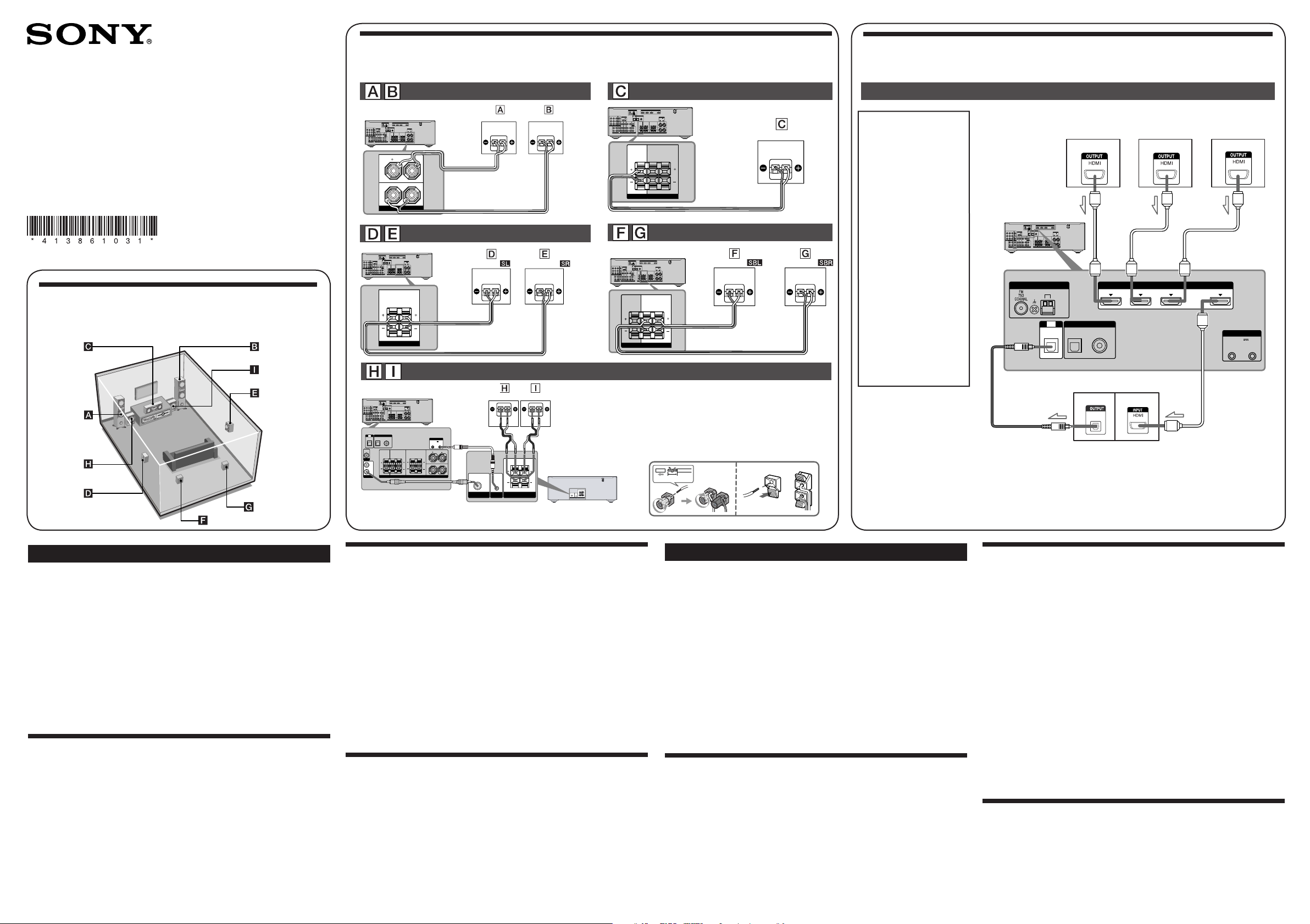
3: Connecting other components
This is an example of how to connect this receiver and your components. Refer to
step 3 and 4 of “Getting started” of the operating instructions supplied with this
receiver for details on other connections and other components.
Français
Ce guide d’installation décrit comment raccorder un lecteur DVD, un lecteur de
disques Blu-ray, un tuner satellite ou un décodeur, un téléviseur, des enceintes et
un caisson de graves afin que vous puissiez bénéficier du son surround multicanal.
Reportez-vous au mode d’emploi fourni avec l’ampli-tuner pour plus de détails.
Les illustrations du guide désignent les différentes enceintes, de Aà I.
AEnceinte avant (gauche)
BEnceinte avant (droite)
CEnceinte centrale
DEnceinte surround (gauche)
EEnceinte surround (droite)
FEnceinte surround arrière (gauche)
GEnceinte surround arrière (droite)
HCaisson de graves
ICaisson de graves
1: Installation des enceintes
Les illustrations ci-dessus montrent l’exemple d’une configuration de système à sept
enceintes et deux caissons de graves. Reportez-vous au mode d’emploi fourni avec
l’ampli-tuner.
A propos de la position des enceintes
Les enceintes avant, l’enceinte centrale et le caisson de graves disposent d’un
blindage magnétique afi n de permettre leur installation à proximité d’un téléviseur.
Toutefois, étant donné que les enceintes surround et surround arrière ne disposent
pas d’un blindage magnétique, il est recommandé de les éloigner légèrement du
téléviseur.
2: Raccordement des enceintes et des caissons de
graves
Les illustrations ci-dessus indique comment raccorder les enceintes. Avant de
procéder au raccordement des enceintes, vérifiez l’étiquette des enceintes située sur le
panneau arrière des enceintes pour en connaître le type.
Pour obtenir davantage d’informations, reportez-vous au mode d’emploi fourni avec
l’ampli-tuner.
A propos des cordons d’enceintes
• Utilisez les cordons d’enceintes longs pour raccorder les enceintes surround et
surround arrière, et les cordons d’enceintes courts pour raccorder les enceintes
avant.
• Branchez le cordon sur lequel est fixée l’étiquette « CENTER » sur l’enceinte
centrale.
• Utilisez les cordons d’enceintes rouge et noir pour raccorder les caissons de graves.
Le fil rouge présente une polarité positive (+) et doit être raccordé à la borne
positive (+) de l’enceinte. Raccordez le fil noir à la borne négative (–) de l’enceinte.
A propos des prises d’enceinte
• Raccordez la prise 3à la prise 3de l’ampli-tuner et la prise #à la prise #de
l’ampli-tuner.
• Reportez-vous à l’illustration ci-dessus pour plus de détails sur le raccordement des
cordons d’enceinte.
3: Raccordement d’autres éléments
Ce guide donne un exemple de raccordement de cet ampli-tuner et de vos éléments.
Reportez-vous à l’étape 3 de la section « Préparatifs » du mode d’emploi fourni avec
cet ampli-tuner pour plus de détails sur le raccordement à d’autres éléments.
DIGITAL
(ASSIGNABLE)
TV
AUDIO
OUT
VIDEO
OUT
IN
OPTICAL
SUBWOOFER
MONITOR
SAT
IN
DVD
IN
DC5V
50mA MAX
OUT OUT
OPTICAL COAXIAL
CENTER SURROUND BACK SURROUND
FRONT
L
L
R
RLR
SPEAKERS
SYSTEM CONTROL
L
R
DIGITAL
(ASSIGNABLE)
DC5V
0.7AMAX
DMPORT
SATIN
SAT
IN
DVDIN BDIN OUT
AM
Y
P
B
/
C
B
COMPONENTVIDEO
OUT IN
P
R
/
C
R
DVD
IN
VIDEO1
IN
MONITOR
OUT
SA-CD
/
CD
/
CD-R
VIDEO1
IN
TV
TV
AUDIO
IN
VIDEO
IN
SAT
AUDIO
OUT AUDIO
OUT
VIDEO
OUT
VIDEO
OUT
IN
OPTICAL
AUDIO
IN
VIDEO
IN
SUBWOOFER
MONITOR
AUDIO
IN
VIDEO
IN
BD
SAT
IN
DVD
IN
DC5V
50mAMAX
OUT OUT
OPTICAL COAXIAL
CENTER SURROUNDBACK SURROUND
FRONT
L
L
R
RLR
HDMIANTENNA
SPEAKERS
SYSTEMCONTROL
SUBWOOFER
AUDIO
IN
SYSTEM
CONTROL
SPEAKERS
IN
SUBWOOFER
SS-WP7500 SS-WP7500
SUBWOOFER ONLY FOR SS-WP7500
SYSTEM
CONTROL
SUBWOOFER SPEAKERS
AUDIO
IN IN
SUBWOOFERONLYFOR SS-WP7500
SUBWOOFER
ASpeaker cord/Cordons d’enceintes
BMonaural audio cord/Cordon audio mono
CSystem control cable/Câble de commande système
10 mm
Note
Be sure to change the
factory setting of the
DVD input button on the
remote so that you can
use the button to control
your DVD player. For
details, see “Changing
button assignments” in the
operating instructions of the
receiver.
Remarque
Changez les réglages par
défaut de la touche d’entrée
DVD de la télécommande
afin de pouvoir l’utiliser
pour commander votre
lecteur DVD. Pour obtenir
davantage d’informations,
reportez-vous à la section
« Modification de l’affectation
des touches »
du mode
d’emploi de l’ampli-tuner.
DIGITAL (ASSIGNABLE)
SAT IN DVD I N OUT
AM
TV
IN SAT
IN
DVD
IN
DC5V
50mA MAX
OUT OUT
OPTICAL COAXIAL
ANTENNA
SYSTEM CONTROL
DIGITAL
OPTICAL
BD IN
HDMI
L
R
DIGITAL
(ASSIGNABLE)
DC5V
0.7AMAX
DMPORT
SATIN
SAT
IN
DVDIN BDIN OUT
AM
Y
P
B
/
C
B
COMPONENTVIDEO
OUT IN
P
R
/
C
R
DVD
IN
VIDEO1
IN
MONITOR
OUT
SA-CD
/
CD
/
CD-R
VIDEO1
IN
TV
TV
AUDIO
IN
VIDEO
IN
SAT
AUDIO
OUT AUDIO
OUT
VIDEO
OUT
VIDEO
OUT
IN
OPTICAL
AUDIO
IN
VIDEO
IN
SUBWOOFER
MONITOR
AUDIO
IN
VIDEO
IN
BD
SAT
IN
DVD
IN
DC5V
50mAMAX
OUT OUT
OPTICAL COAXIAL
CENTER SURROUNDBACK SURROUND
FRONT
L
L
R
RLR
HDMIANTENNA
SPEAKERS
SYSTEMCONTROL
OPTICAL
DHDMI cable/Câble HDMI
EOptical digital cord/Cordon numérique optique
DVD player/
Lecteur DVD
TV/Téléviseur
Satellite tuner or Set-top box/
Tuner satellite ou Décodeur
Blu-ray disc player/
Lecteur de disques
Blu-ray
A
A
C
B
Cords used for connection (supplied)/
Cordons utilisés pour le raccordement (fourni)
Cords used for connection (not supplied)/
Cordons utilisés pour le raccordement (non fourni)
4138610311_DDW7500_GBFR_A3.indd 14138610311_DDW7500_GBFR_A3.indd 1 5/22/2009 3:51:19 PM5/22/2009 3:51:19 PM


