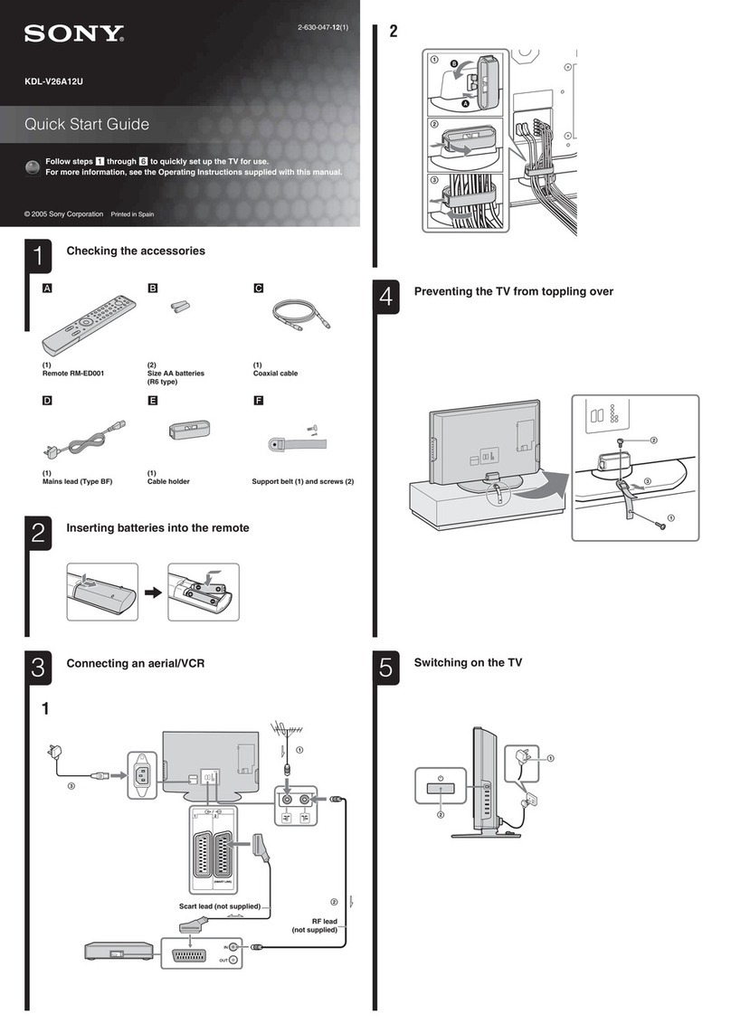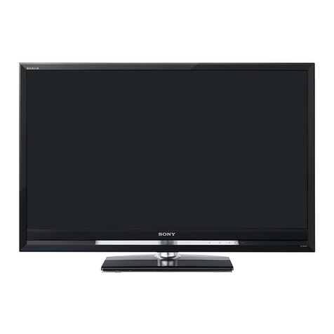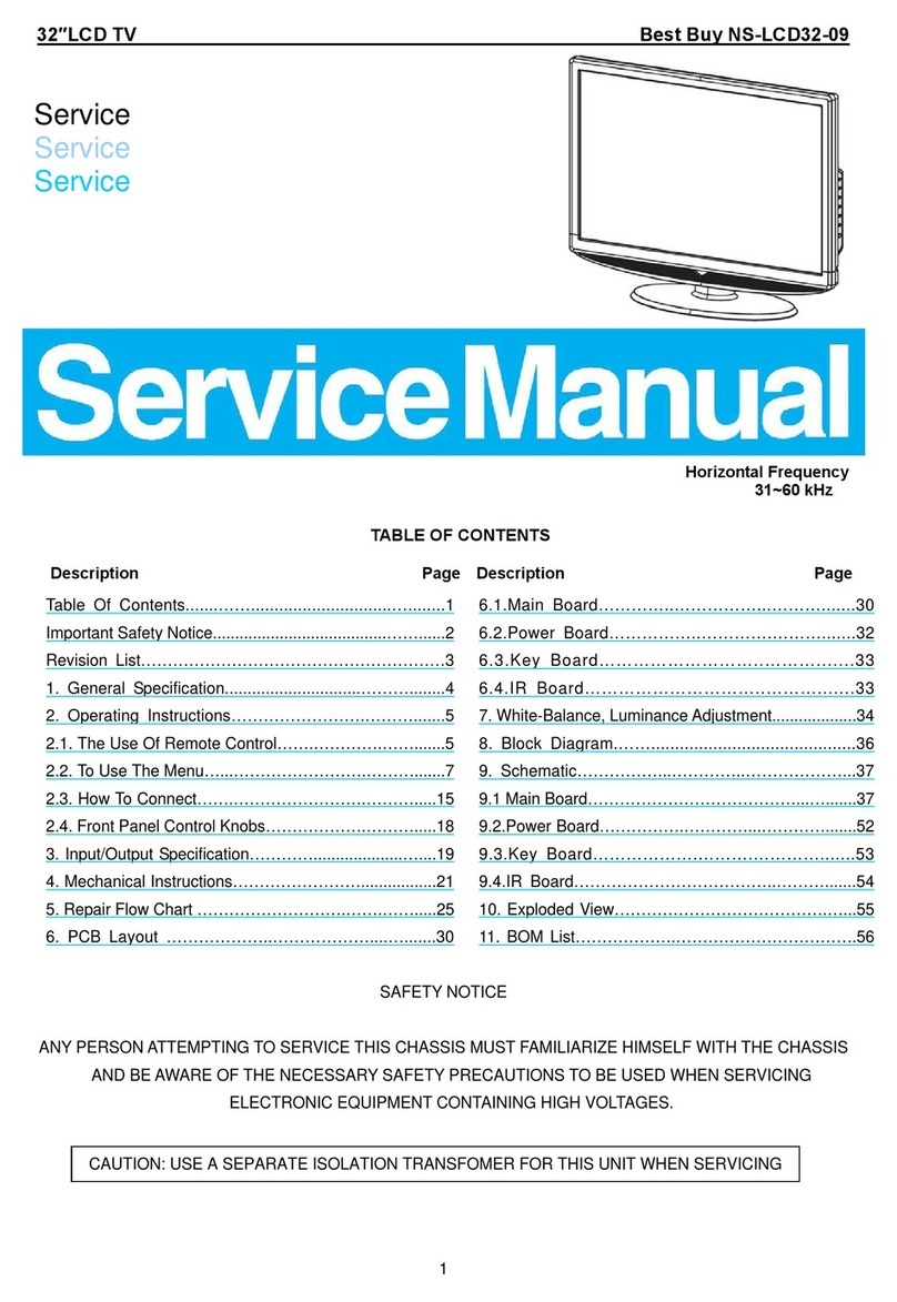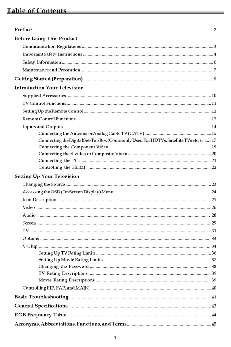
TABLE OF CONTENTS
Section Title Page
1. SAFETY NOTES
1-1. Warnings and Caution………………………………………………………. 5
1-2. Caution Handling of LCD Panel ......…………….................................... 5
Section Title Page
4. SERVICE ADJUSTMENTS
4-1.
ccessing Service Mode ..................................................................... 218
4-2. Transition of Each Micro’s Service Mode……….……………………… 218
-
Change Data by Service Mode 1…………………………………..…….
1-3. Safety Check Out ........................……………......................................... 6
1-4. Leakage Test .......................................................................................... 6
1-5. How to Find a Good Earth Ground………………………………………… 7
1-6. Lead Free Information….…………………………………………………… 7
1-7. Handling the Flexible Flat Cable (FFC)……………………………………. 7
4-4. Save Changing Data by Service Mode 1……………………………… 218
4-5. Change Data by Service Mode 2……………………………………….. 219
4-6. Save Changing Data by Service Mode 2……………………………… 220
4-7. Restore WB/Gamma Adj. Data to B Board…………………………….. 221
4-8. WB Adjustment by Service Mode……………………………………….. 221
-
-
AUO Panel) ………………………………….
1-8. Procedure to remove Rear Cover…………………………........................ 8
1-9. Procedure to re-assemble Rear Cover……………………………………. 10
1-10. Caution Of Rear Cover …………………………………………………….. 11
1-11. Instruction about Disassembling Smart Core……………………………. 12
2 SELF DIAGNOSTIC FUNCTION
4-10. VCOM Adjustment (HFR-SDC Panel) …………………………………. 223
4-11. REC Setting………………………………………................................... 223
4-12. Reset Panel Operation Time………………………………………......... 224
4-13. Set to Shipping Condition……………………………………….............. 224
4-14. Summary of Service Control……………………………………….......... 224
-
Service Menu Tree………………………………………........................
.
2-1. Overview of Control Buttons ................................................................... 16
2-2. LED Display Control ………..................................................................... 17
2-3. LED Pattern………………........................................................................ 17
2-4. Standby LED Error Display…………………………………………………. 17
Tree………………………………………........................
4-16. How to Enter Self Diagnosis Display…………………………………… 226
4-17. Updating the software……………………………………………………. 228
4-18. Non network function…………………………………………………….. 228
4-17. One Step Touch Key function……………………………………………. 230
2-5. Triage Chart ............................................................................................ 18
3. TROUBLE SHOOTING
3-1. No Power…….……………………………………………………………….. 19
3-2. LED Blinking……………….………………………………………............... 35
.
5-1. Circuit Board Location ......................................................................... 231
5-2. Block Diagram...................................................................................... 232
5-3. Connector Diagram ………………………………………...................... 240
.
…………………………….........................................................
3-4. Analog Signal Path.................................................................................. 118
3-5. No Picture................................................................................................. 119
3-6. Input Skip Function……………………………………………………. 205
3-7. Side Buttons Malfunction……………………………………………………. 206
3-8. IR Remote Commande
Malfunction………………………………………. 207
Please refer Service Manual – Unique for below information :
-Safety Warnings
-Wire Dressing
3-9. Light Sensor Error…………………………………………………………… 208
3-10. Network Malfunction: Ethernet (Wired)……………………………………. 209
3-11. Wireless Network Malfunction……………………………………………. 213
3-12. Bluetooth Malfunction…………………………………………………. 215
3-13. 3D Glasses
Active
Malfunction…………………………………………… 216
4
-
-Disassembly and Exploded View.
3-14. HD Rec Malfunction……………………………………………………….. 217
3-15. Android Application Malfunction…………………………………………… 218
