5
Features / Precautions
Features
The UWP-X5 Wireless Microphone
Package consists of a transmitter (body-
pack transmitter (UTX-B1)), a receiver
(diversity tuner module (URX-M1)), and
the accessories. The UWP-X5 can be used
with the tuner base unit or the powered
mixer for AV presentations.
The UWP-X5 is not compatible with
conventional WRT series transmitters,
WRR series tuners, or WRU series tuner
units.
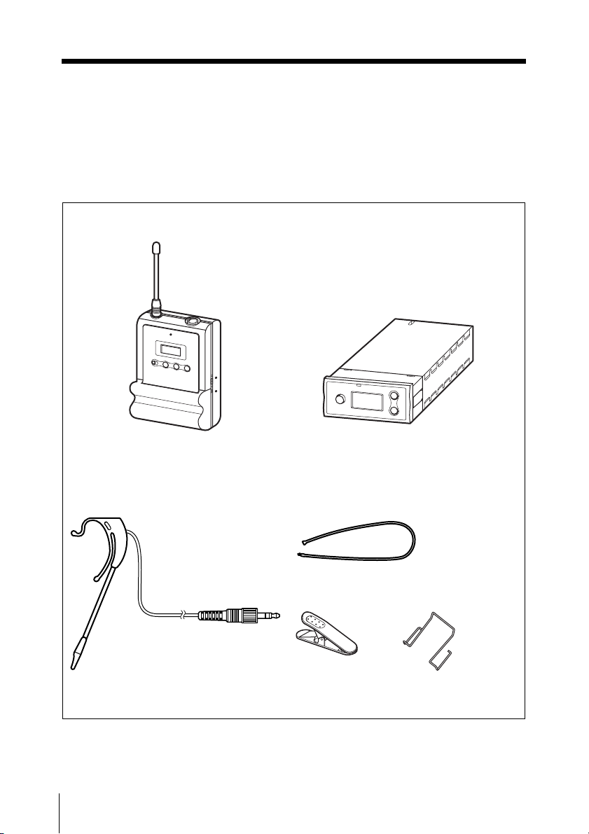
The featured components of the package are
described below.
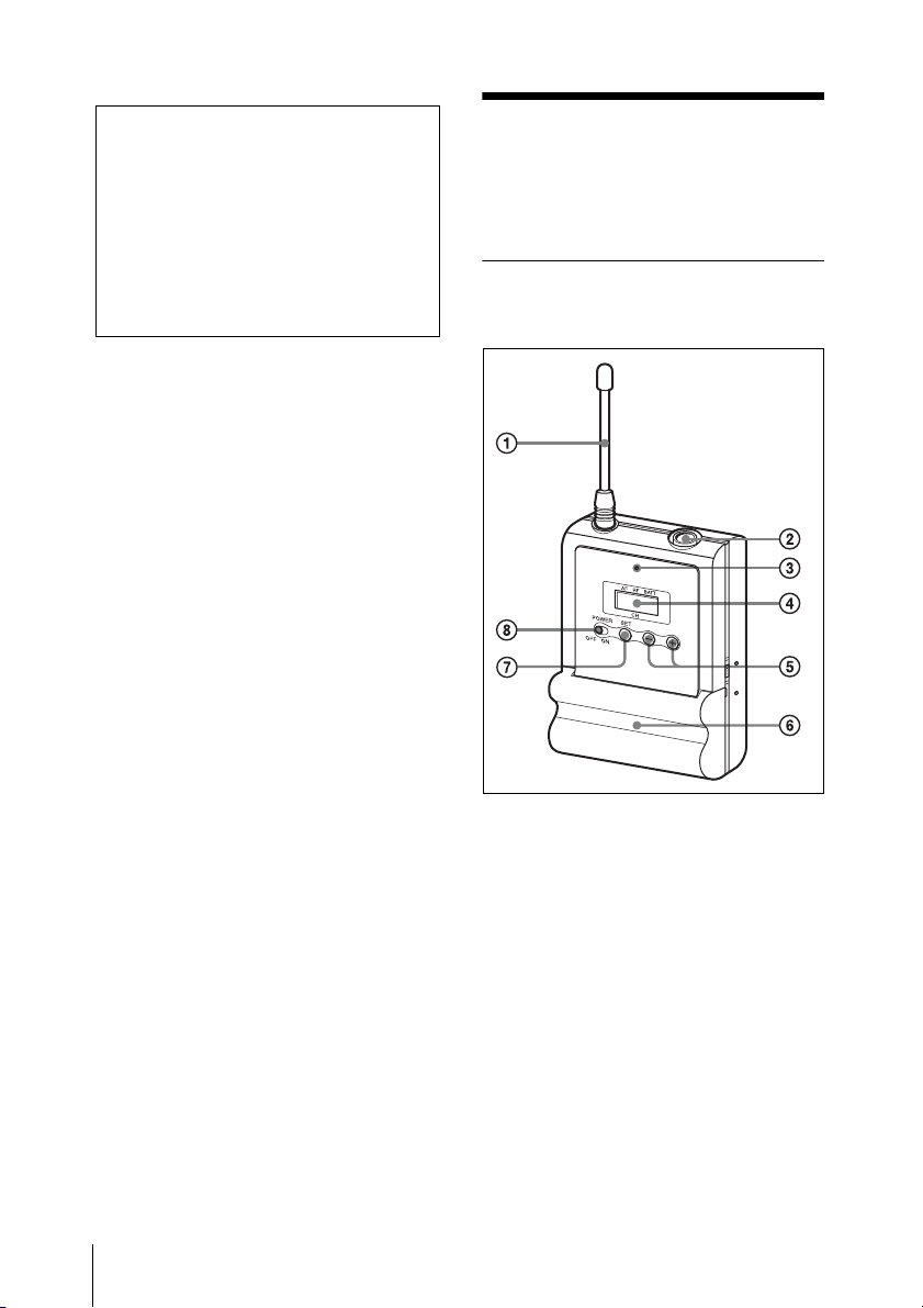
Body-pack transmitter (UTX-
B1)
This is a small and lightweight transmitter
with a crystal-controlled PLL (phase lock
loop) synthesized system and a BMP-type
microphone input connector. The RF power
output can be set at 10 mW or at 2 mW.
Diversity tuner module (URX-
M1)
This tuner module can be incorporated into
the MB-X6 Tuner Base Unit or SRP-X500P
Powered Mixer.
Head-set type microphone
(supplied)
This electret condenser microphone is
equipped with the omni-directional capsule
to obtain sound with clarity and quality, ear
clip to easily wear on either ear, and flexible
boom allowing you to finely adjust the
position and angle of the microphone.
Precautions
• The UWP-X5 units must be used within
a temperature range of 0°C to 40°C (32°F
to 104°F).
• Operating the UWP-X5 units near
electrical equipment (motors,
transformers, or dimmers) may cause it to
be affected by electromagnetic induction.
Keep the UWP-X5 units as far from such
equipment as possible.
• The presence of the lighting equipment
may produce electrical interference over
the entire frequency range. Position the
UWP-X5 units so that interference is
minimized.
• To avoid degradation of the signal to-
noise ratio, do not use the UWP-X5 units
in noisy places or in locations subject to
vibration, such as the following:
- near electrical equipment, such as
motors, transformers or dimmers
- near air conditioning equipment or
places subject to direct air flow from
an air conditioner
- near public address loudspeakers
- where adjacent equipment might
knock against the tuner
Keep the UWP-X5 units as far from such
equipment as possible or use buffering
material.
• Clean the surface and the connectors of
the UWP-X5 units with a dry, soft cloth.
Never use thinner, benzene, alcohol or
any other chemicals, since these may mar
the finish.
Note