Features
4
Models Available Separately
The transmitter and receiver in each package are available
for purchase separately. The components provided with
each product are given below.
ZTX-M02RC
• Handheld microphone (ZTX-M02RC) (1)
• Mic holder (1)
• Before Use (1) (E model includes 2)
• Operating Instructions (CD-ROM) (1)
• Warranty card (1) (for KR model only)
• Warranty booklet (1) (for E and SYV models only)
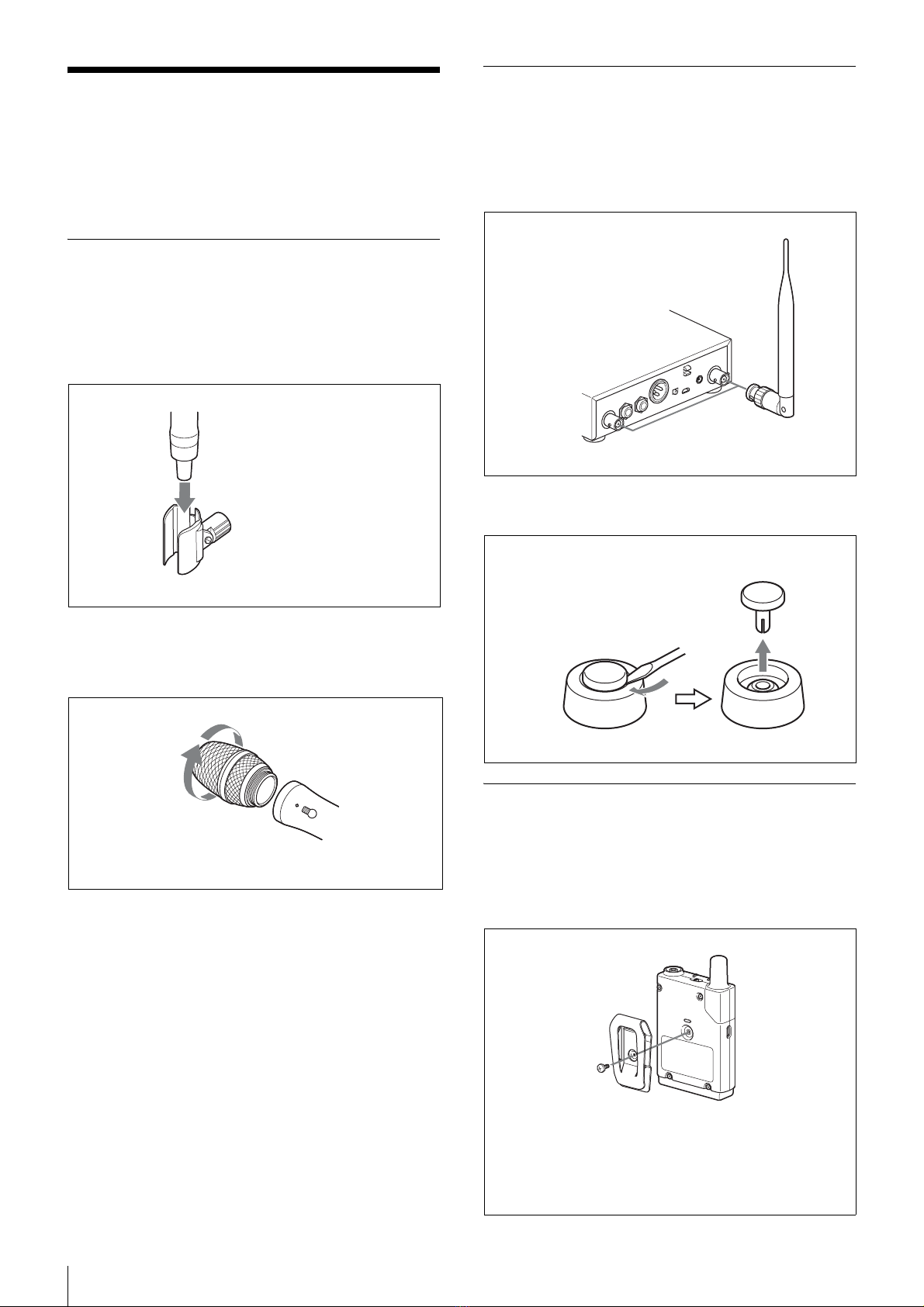
ZTX-B02RC
• Body-pack transmitter (ZTX-B02RC) (1)
• Belt clip (1)
• Belt clip screw (1)
• Switch concealer (1)
• Before Use (1) (E model includes 2)
• Operating Instructions (CD-ROM) (1)
• Warranty card (1) (for KR model only)
• Warranty booklet (1) (for E and SYV models only)
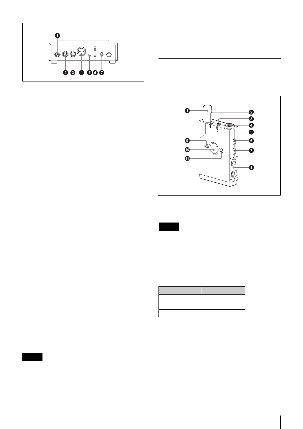
ZRX-HR70
• Half-rack receiver (ZRX-HR70) (1)
• AC adapter (1)
•Antenna(2)
• Before Use (1)
• Operating Instructions (CD-ROM) (1)
• Warranty card (1) (for UC model only)
Features
The DWZ series is a digital wireless system that
combines Sony’s consistently developed superior audio
technology, highly reliable wireless technology, and
state-of-the-art digital signal processing technology.
Using an unlicensed 2.4 GHz band, the system provides
wide-range functionality with simple, user-friendly
operability.
By providing a package that is optimized for specific
usage environments, the system offers a wireless solution
to users ranging from those inexperienced with wireless
systems to seasoned professionals.
Superb audio quality
By transmitting audio signals via 24-bit high-quality
linear PCM digital transmission (available only when the
RF mode is set to Narrow Mode (NARROW)), without
signal compression, decompression, or similar
processing, the system provides superb audio quality and
high-bandwidth transmissions that approach that of wired
microphones.
High reliability
By allowing you to select from two RF modes based on
your intended use and incorporating Sony’s unique data
processing technology, the system provides highly-
reliable wireless transmission in wireless LAN
environments. In addition, the two RF modes each consist
of six channels, allowing you to select the appropriate RF
mode and channel according to your intended purpose.
The receiver is equipped with two antennas with the
antenna with the best reception status selected
automatically via space diversity, providing stable
reception with minimized audio breakup and noise
occurrences.
Highly confidential transmissions are also possible using
the 128-bit AES (Advanced Encryption Standard).
DWZ-M70
This package includes a rechargeable handheld
microphone (transmitter: ZTX-M02RC) and a half-rack
receiver (receiver: ZRX-HR70) and is ideal for use during
speeches and vocal performances.
DWZ-B70HL
This package can connect to headset microphones and
lavalier microphones, and includes a rechargeable body-
pack microphone (transmitter: ZTX-B02RC) and a half-
rack receiver (receiver: ZRX-HR70).
ZTX-M02RC
A microphone designed with a sturdy metal body.
Using an optional battery charger (BC-DWZ1) and
nickel-metal-hydride rechargeable batteries makes