8
Features
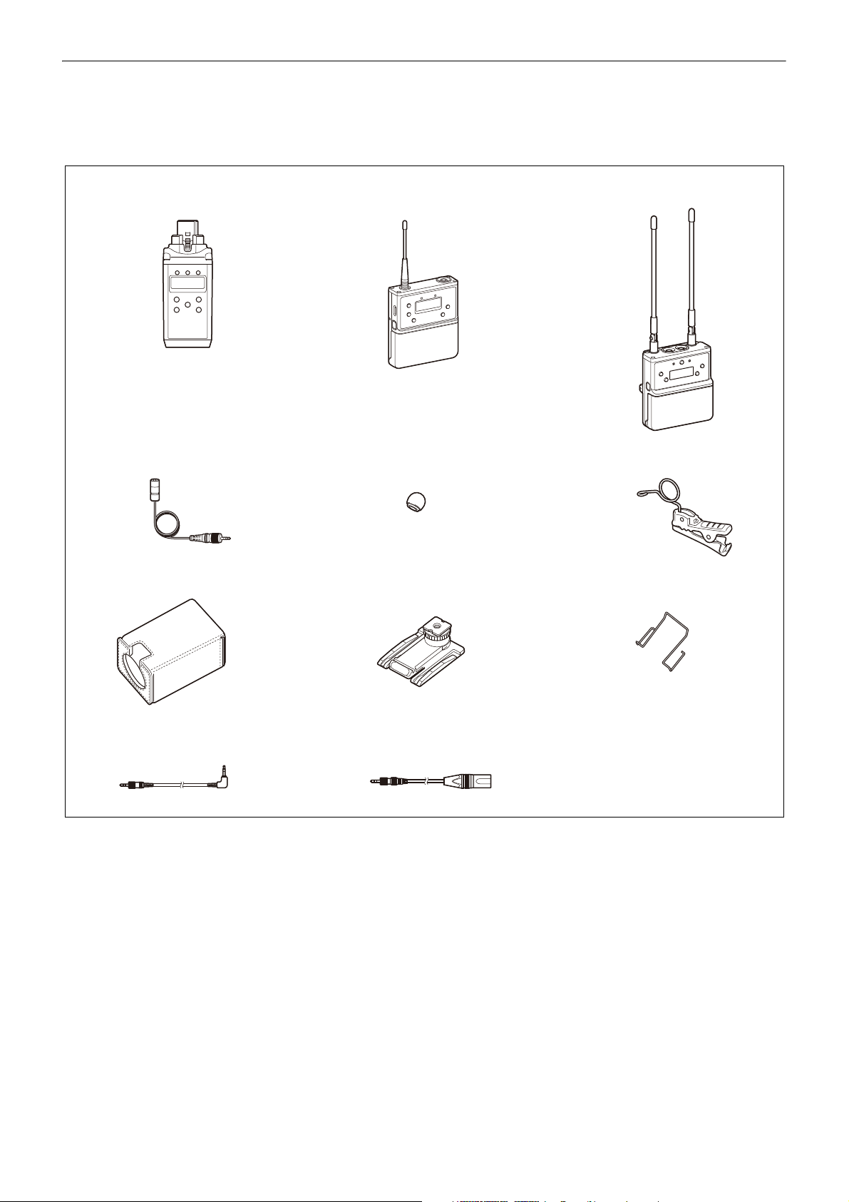
The UWP-D21/D22/D26/D27 (UWP-D series) Wireless
Microphone Packages comprise a transmitter (body-pack
transmitter (UTX-B40), hand-held microphone
(UTX-M40), or plug-on transmitter (UTX-P40)) and a
receiver (portable diversity tuner (URX-P40 or
URX-P41D)). In combination with a compact camcorder
or interchangeable-lens digital camera, the packages can
be used for various purposes, such as ENG (Electronic
News Gathering), EFP (Electronic Field Production),
sports events, and weddings.
The features of each package are described below.
UWP-D21
• High quality sound with Sony Digital Audio Processing
• “NFC SYNC” function for quick and easy secure
channel setting
• True diversity for stable signal reception
• Auto gain mode volume control
•+15dB gain volume boost mode for off-mic audio
• Line input available
• Channel memory function for fast switching between
two receiver frequencies
• Transmitter frequency sent to receiver
• Headphone output for monitoring
• Monitor mode for using a receiver as an ear monitor
• Variable muting function
• Compatibility with Sony WL-800/UWP/UWP-D series
• Output level control for receiver
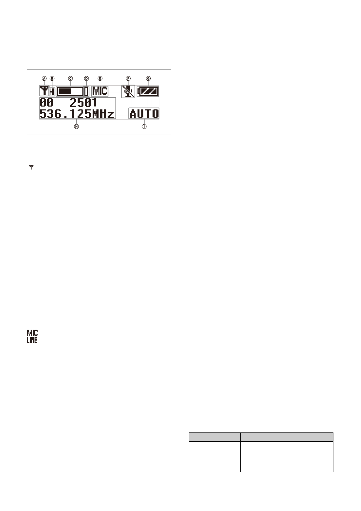
• High visibility OLED display for indoor/outdoor use
• USB for power supply
• Digital audio interface support using SMAD-P5 multi-
interface shoe-mount adaptor (option)*
* For details on cameras that support this function, visit
the Sony website.
UWP-D22
• High quality sound with Sony Digital Audio Processing
• “NFC SYNC” function for quick and easy secure
channel setting
• True diversity for stable signal reception
• Interchangeable head for wide choice of microphone
capsule
• Auto gain mode volume control
• +15 dB gain volume boost mode for off-mic audio
• Channel memory function for fast switching between
two receiver frequencies
• Transmitter frequency sent to receiver
• Headphone output for monitoring
• Monitor mode for using a receiver as an ear monitor
• Variable muting function
• Compatibility with Sony WL-800/UWP/UWP-D series
• Output level control for receiver
• High visibility OLED display for indoor/outdoor use
• USB connector for power supply (URX-P40 only)
• Digital audio interface support using SMAD-P5 multi-
interface shoe-mount adaptor (option)*
* For details on cameras that support this function, visit
the Sony website.
UWP-D26
• High quality sound with Sony Digital Audio Processing
• “NFC SYNC” function for quick and easy secure
channel setting
• True diversity for stable signal reception
• Auto gain mode volume control
•+15dB gain volume boost mode for off-mic audio
• Line input available
• +48V power supply (plug-on transmitter)
• Channel memory function for fast switching between
two receiver frequencies
• Transmitter frequency sent to receiver
• Headphone output for monitoring
• Monitor mode for using a receiver as an ear monitor
• Variable muting function
• Compatibility with Sony WL-800/UWP series
• Output level control for receiver
• High visibility OLED display for indoor/outdoor use
• USB for power supply
• Digital audio interface support using SMAD-P5 multi-
interface shoe-mount adaptor (option)*
* For details on cameras that support this function, visit
the Sony website.
UWP-D27
• High quality sound with Sony Digital Audio Processing
• “NFC SYNC” function for quick and easy secure
channel setting
• Space-diversity reception method for low dropouts
(higher stability, true diversity reception in single
channel operation mode)
• External microphone input connector supports plug-in
power type external microphones and Sony BMP type
lavalier microphones
• Built-in mixing function for flexible mixing and output
of input signals
• Auto gain mode volume control
• +15 dB gain volume boost mode for off-mic audio
• Line input available
• ALL BAND scan function that scans all available
frequency bands (Japan model, Korea model, 90U
model, and E model do not have this function)
• Channel memory function for fast switching between
two receiver frequencies
• Transmitter frequency sent to receiver
• Headphone output for monitoring
• Monitor mode for using a receiver as an ear monitor
• Variable muting function
• Compatibility with Sony WL-800/UWP/UWP-D series