Sony ECM-S930C User manual

1
Ver 1.0 2001. 03
SERVICE MANUAL
US Model
Canadian Model
E Model
ECM-S930C
General
Type Stereo (employing the X-Y stereo system),
electret condenser microphone
Microphone cord 2.2 mm dia. two core-shielded,
OFC (Oxygen-free copper) cord with the
gold-plated L-shaped stereo miniplug
Length: Approx. 30 cm (11 7/8 inches)
Dimensions Approx. 55 ×34 ×40 mm (W ×H ×D)
(2 1/4 ×1 3/8 ×1 5/8 inches)
(without the projecting parts)
Mass Approx. 40 g (1 lb. 4 oz.)
including battery and cord
Supplied accessories Carrying case (1)
Performance
Frequency response 100 – 15,000 Hz
Directivity Unidirectional
×2 (Directive angle: 90° or 120°) (switchable)
Output impedance 2.2 kilohm ±30 %
Sensitivity Open circuit output level *1 : –43 ±4 dB (7 mV)
Difference between L and R channel sensitivity:
Less than 3 dB
Power requirements Lithium battery CR2025
Continuous lasting hours: Approx. 350 hours
Plug-in power
Maximum input sound pressure level *2
More than 110 dBSPL
Dynamic range More than 84 dB
Operating temperature range
0°C to 40°C (32°F to 104°F)
*1 0 dB=1 V/Pa, 1,000 Hz (1 Pa=10 µbar=94 dBSPL)
*2 1 % wave distortion is present at 1,000 Hz
(0 dBSPL=2 ×10⁻⁵ Pa)
Design and specifications are subject to change without
notice.
SPECIFICATIONS
Sony Corporation
Audio Entertainment Group
General Engineering Dept.
9-927-989-11
2001C0400-1
© 2001. 3
ELECTRET CONDENSER MICROPHONE
Notes on Chip Component Replacement
•Never reuse a disconnected chip component.
•Notice that the minus side of a tantalum capacitor may be
damaged by heat.

2
ECM-S930C SECTION 1
GENERAL This section is extracted
from instruction manual.
AInstalling the battery (See fig.A)
1 Open the battery compartment lid.
2 Place the CR2025 battery (not supplied) with the + side facing upward.
Be sure to place the battery with polarity positioned correctly.
Battery life
The Sony CR2025 lithium battery (not supplied) gives continuous operation on the
microphone for about 350 hours. When you turn the power on, the battery check
indicator lights momentarily. When the battery becomes weak, the indicator lights
dimly or does not light at all. In this case, replace the battery with a new one. (Sony
CR2025 lithium battery (not supplied)). To avoid battery wear or leakage, be sure to
turn the power off after using the microphone.
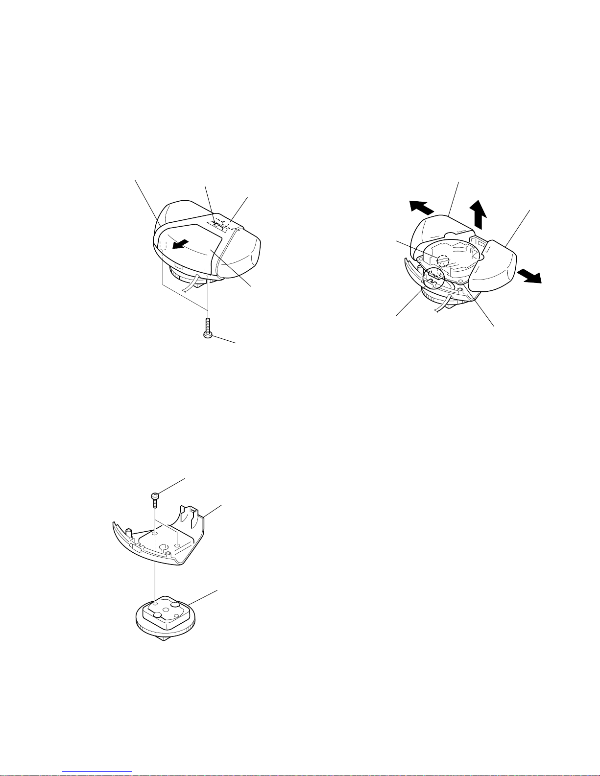
When the battery compartment lid comes off
1Hold down part Awith a thumb so that it does not slide.
2Insert one of the parts of Ainto the projecting part Bof the battery compartment
and then insert the other part while pressing toward the inside.
Removing the battery(See fig.B)
When to replace the battery
When the power is turned on, the battery check indicator lights momentarily. When
the battery become weak, the indicator remains dimly lit or does not light at all. In this
case, replace the battery with Sony CR2025 lithium battery. Use of another battery may
present a risk of fire or explosion.
Under normal conditions of use, the battery will last approximately 350 hours.
Notes on lithium battery
• Keep the lithium battery out of the reach of children. Should the battery be
swallowed, immediately consult a doctor.
• Wipe the battery with a dry cloth to assure good contact.
• Be sure to observe the correct polarity when installing the battery.
• Do not hold the battery with metallic tweezers. Doing so can cause a short-circuit.
WARNING
Battery may explode if mistreated.
Do not recharge, disassemble or dispose of in fire.
1
2
B
12
+ side
pôle +
lado +
– side
pôle –
lado –
Lithium battery CR2025 (not supplied)
Pileau lithium CR2025 (non fournie)
Pilade litio CR2025 (no suministrada)
A
B
Parts Identification and Uses (See fig.D)
1Directive angle switch
Set the switch according to the sound source.
90˚: Use to pick up a relatively narrower sound source (instrumental solo,
conversation, etc.), to provide a clear stereo sound image focused on target
source.
120˚: Use to pick up a relatively wider sound source (orchestra, chorus, stage
play, etc.), to provide a natural stereo sound image with full reality.
The above are guidelines for selecting an appropriate angle. Although following
these guidelines is encouraged, you can freely select either angle according to
your own preference.
Note
If you switch the angle during recording, noise may occure.
2Gold-plated triple-pole stereo miniplug
Connect to the MIC jack of your recording equipment (video camera, etc.)
3Battery compartment lid
4Power switch
ON: Select when the microphone works with the battery.
OFF: Select when the microphone works with plug-in power or when you turn it
off.
When you use a Sony video camera with plug-in power system, set the power
switch to OFF.
5Battery check indicator
When the power is turned on, this indicator lights momentarily. When the battery
becomes weak, the indicator remains dimly lit or does not light at all. In this case,
replace the battery with a new one.
D
1
2
3
4
5

3
ECM-S930C
SECTION 2
DISASSEMBLY
Note : Follow the disassembly procedure in the numerical order given.
2-1. CASE, UPPER
Note : When installing, fit the selection knob and awitch (SW1)
(center position)
2-2. AMP BOARD
Note : When installing, fit the power knob and awitch (SW2)
2-3. HOLDER ASSY, SHOE
2
4case, upper
3claw
1B 1.7
lid, battery cas
e
knob, selection
4AMP board
grille
grille
knob, power
2
1
2
3Removal the solder.
3holder assy, shoe
2case, lower
1P 2.6x4

4
ECM-S930C SECTION 3
DIAGRAMS
3-1. PRINTED WIRING BOARD
1
A
B
C
D
E
F
G
H
I
234567
AMP BOARD (CONDUCTOR SIDE)
AMP BOARD (COMPONENT SIDE)
R202
C202
R201 R101
R104
R204
C3
R3
C2
C4
C203
C103
C102
R2
SW1
(DIRECTIVE ANGLE)
120˚ 90˚
C201
R203
R1
C1
C101
R103
R102
-1
-2
D2
D1
SW2(POWER)
ON OFF
D3
ON
BATTERY
CHECK
LAMP
MICROPHONE
CAPSULE(R CH)
MIC201
Q201
S
RED
WHT
GRY
MICROPHONE
CAPSULE(L CH)
MIC101
Q101
S
RED
WHT
GRY
BLU
RED
MINI PLUG
(MIC OUT)
1-679-165-
11
(11)
1-679-165-
11
(11)
LITHIUM
BATTERY
CR-2025
3V

5
ECM-S930C
3-2. SCHEMATIC DIAGRAM
(DIRECTIVE ANGLE) (POWER)
(POWER)
Note on Printed Wiring Boards:
•X: parts extracted from the component side.
•Y: parts extracted from the conductor side.
•z: Through hole.
•: Pattern from the side which enables seeing.
Caution:
Pattern face side: Partson thepattern faceside seenfrom
(Conductor Side) the pattern face are indicated.
Parts face side: Parts on the parts face side seen from
(Component Side) the parts face are indicated.
Note on Schematic Diagram:
• All capacitors are in µF unless otherwise noted. pF: µµF
50 WV or less are not indicated except for electrolytics
and tantalums.
• All resistors are in Ωand 1/4W or less unless otherwise
specified.
•C: panel designation.
•A: B+ Line.
• Power voltage is dc 3 V and fed with regulated dc power
supply from battery terminal.
• Voltage is dc with respect to ground under no-signal
(detuned) condition.
• Voltagesaretakenwith aVOM (Inputimpedance10 MΩ).
Voltage variations may be noted due to normal produc-
tion tolerances.
• Signal path.
F: AUDIO

6
ECM-S930C SECTION 4
EXPLODED VIEWS
Ref. No. Part No. Description Remark Ref. No. Part No. Description Remark
NOTE:
•The mechanical parts with no reference
number in the exploded views are not supplied.
•Items marked “*”are not stocked since
they are seldom required for routine service.
Some delay should be anticipated
when ordering these items.
•Accessories and packing materials are given in
the last of this parts list.
1
2
3
4
1
5
6
7
89
10
11
12
14
13
15
12
11
16
18
17 19
20
20
Q201
Q101
MIC101
MIC201
21 22
21
22
*1 3-222-928-01 HOLDER, UNIT
*2 1-679-165-11 AMP BOARD
3 3-224-339-02 SHEET, BATTERY
4 1-550-104-33 HOLDER, BATTERY
5 3-222-923-01 LID, BATTERY CASE
6 3-222-907-01 HINGE
7 3-222-926-01 KNOB, SELECTION
8 3-222-921-01 CASE, UPPER
*9 3-222-927-01 LEVER, SELECTION
10 3-686-420-01 SCREW (P1.4X2.5), TAPPING
11 3-222-929-01 GRILLE
12 3-222-930-01 SCREEN, GRILLE
13 3-222-922-01 CASE, LOWER
14 1-790-506-21 CORD, MICROPHONE (2 CORE)
15 X-3379-657-1 HOLDER ASSY, SHOE
16 3-222-925-01 KNOB, POWER
17 3-222-924-01 WINDOW, LED
18 3-318-203-94 SCREW (B1.7), TAPPING
19 7-621-259-25 SCREW +P 2.6X4
20 2-545-447-01 HOLDER, CAPSULE
21 2-523-713-00 TERMINAL
*22 2-532-219-00 TERMINAL, GROUND
MIC101 8-814-289-90 CAPSULE, MICROPHONE CU14-03 (L-CH)
MIC201 8-814-289-90 CAPSULE, MICROPHONE CU14-03 (R-CH)
Q101 8-729-037-42 FET 2SK1578-A
Q201 8-729-037-42 FET 2SK1578-A

7
ECM-S930C
SECTION 5
ELECTRICAL PARTS LIST
NOTE:
• Due to standardization, replacements in
the parts list may be different from the
parts specified in the diagrams or the
components used on the set.
• RESISTORS
All resistors are in ohms.
METAL:Metal-film resistor.
METAL OXIDE: Metal oxide-film resistor.
F:nonflammable
• CAPACITORS
uF : µF
• COILS
uH : µH
• Items marked “*” are not stocked since
they are seldom required for routine service.
Some delay should be anticipated
when ordering these items.
• SEMICONDUCTORS
In each case, u : µ, for example:
uA.. : µA.. uPA.. : µPA..
uPB.. : µPB.. uPC.. : µPC.. uPD.. : µPD..
Ref. No. Part No. Description Remark Ref. No. Part No. Description Remark
When indicating parts by reference
number, please include the board.
AMP
*1-679-165-11 AMP BOARD
***********
1-550-104-33 HOLDER, BATTERY
< CAPACITOR >
C1 1-127-573-11 CERAMIC CHIP 1uF 10% 16V
C2 1-125-839-11 TANTAL. CHIP 47uF 20% 6.3V
C3 1-164-505-11 CERAMIC CHIP 2.2uF 16V
C4 1-125-839-11 TANTAL. CHIP 47uF 20% 6.3V
C101 1-162-964-11 CERAMIC CHIP 0.001uF 10% 50V
C102 1-104-760-11 CERAMIC CHIP 0.047uF 10% 50V
C103 1-163-009-11 CERAMIC CHIP 0.001uF 10% 50V
C201 1-162-964-11 CERAMIC CHIP 0.001uF 10% 50V
C202 1-104-760-11 CERAMIC CHIP 0.047uF 10% 50V
C203 1-163-009-11 CERAMIC CHIP 0.001uF 10% 50V
< DIODE >
D1 8-719-049-09 DIODE 1SS367-T3SONY
D2 8-719-072-95 DIODE 015AZ3.9-X-TPL3
D3 8-719-052-72 LED CL-220HR-C (ON)
< RESISTOR >
R1 1-216-832-11 METAL CHIP 8.2K 5% 1/16W
R2 1-216-813-11 METAL CHIP 220 5% 1/16W
R3 1-216-833-11 METAL CHIP 10K 5% 1/16W
R101 1-216-994-11 RES-CHIP 13K 5% 1/16W
R102 1-216-817-11 METAL CHIP 470 5% 1/16W
R103 1-216-817-11 METAL CHIP 470 5% 1/16W
R104 1-216-828-11 METAL CHIP 3.9K 5% 1/16W
R201 1-216-994-11 RES-CHIP 13K 5% 1/16W
R202 1-216-817-11 METAL CHIP 470 5% 1/16W
R203 1-216-817-11 METAL CHIP 470 5% 1/16W
R204 1-216-828-11 METAL CHIP 3.9K 5% 1/16W
< SWITCH >
SW1 1-762-741-11 SWITCH, SLIDE (DIRECTIVE ANGLE)
SW2 1-572-018-11 SWITCH, SLIDE (POWER)
*************************************************************
MISCELLANEOUS
***************
14 1-790-506-21 CORD, MICROPHONE (2 CORE)
MIC101 8-814-289-90 CAPSULE, MICROPHONE CU14-03 (L-CH)
MIC201 8-814-289-90 CAPSULE, MICROPHONE CU14-03 (R-CH)
Q101 8-729-037-42 FET 2SK1578-A
Q201 8-729-037-42 FET 2SK1578-A
*************************************************************
ACCESSORIES & PACKING MATERIALS
********************************
3-229-590-11 MANUAL, INSTRUCTION (ENGLISH,FRENCH,
SPANISH)
3-926-629-03 POUCH, CARRYING

8
ECM-S930C
REVISION HISTORY
Clicking the version allows you to jump to the revised page.
Also, clicking the version at the upper right on the revised page allows you to jump to the next revised
page.
Ver. Date Description of Revision
1.0 2001. 03 New
Table of contents
Other Sony Microphone manuals

Sony
Sony DWM-02 User manual

Sony
Sony ECM-R300 User manual

Sony
Sony ECMMS907 - Stereo Type Mic User manual

Sony
Sony ECM -R300 User manual

Sony
Sony ECM-CQP1 User manual

Sony
Sony DWM-02N/14 User manual

Sony
Sony ECMMS907 - Stereo Type Mic User manual

Sony
Sony ECM S80 User manual

Sony
Sony MAS-A100 User manual

Sony
Sony ECM-T115 User manual

Sony
Sony ECM-S930C User manual

Sony
Sony C-357 User manual

Sony
Sony ECM-310BC User manual

Sony
Sony UWP-V1 User manual

Sony
Sony UWP-C1 User manual

Sony
Sony ECM-MS957 - Microphone - Metallic User manual

Sony
Sony ECM-88 User manual

Sony
Sony ECM-SST1 User manual

Sony
Sony DWM02/14 User manual

Sony
Sony XA-MC10 User manual