Sony DMXWL1 - BRAVIA Wireless HD Link User guide

4-114-319-11(1)
Startup Guide
DMX-WL1
© 2008 Sony Corporation
The Startup Guide explains how to connect, setup and use your Wireless Link.

2
Welcome to the World of Wireless Link
Entertainment made simple
Transmitter and Receiver provide a wireless link between your sources and your compatible
BRAVIA HDTV
Real time transmission
For a true gaming experience
Expandability
Support up to 5 source devices (4 HDMI and 1 component)
Simple Operation
Control your BRAVIA HDTV and all connected sources using the supplied remote
Clean and Cable-free
Easy to mount receiver remains concealed behind your compatible BRAVIA HDTV
This product is compatible with Control for HDMI enabled BRAVIA TVs released from 2007.
Please check with your retailer or visit http://www.sonystyle.com/dmxwl1
to view model compatibility.

3
3Slide the receiver unit onto the bracket.
4Connect the receiver unit and TV with the
supplied HDMI cable.
IN
OUT
IN
5Connect the AC power adapter with AC
power cord between the receiver unit and the
wall outlet.
DC IN 9V
to wall outlet
AC power cord
AC power adapter
• See the Reference Guide for information for alternate
attachment methods.
1
Connecting
the Receiver unit
Attaching the Receiver Unit to the
Rear of the TV
Power off your TV before beginning setup.
1Attach the supplied TV Mounting bracket to
the bottom left side of the TV rear panel.
Plastic Fastener
Guide Pin
• Do not push on the head of the Plastic Fastener until you
have inserted the fastener into the hole of the TV.
2Align the slider on the bottom of the receiver
unit with the groove of the TV Mounting
bracket.

4
A
TV
Cable Box
Other Equipment
Transmitter unit
2
Choosing
your setup type
B
C
Controlling the equipment using the supplied remote control
Controlling the equipment using the supplied remote control and sending the
audio output to your Home Theater System
Controlling the equipment using your Home
Theater System
REC
CONNECTSETUP
TOPMENU
MENU
F1F2
BD/DVD
REC PAUSE
MUTINGJUMP
REC STOP
AV POWERTV POWER
DISPLAY
POWER
COMPO-
NENT
IN 5 TV
WIDE
PICTURE
CC
MENU
FREEZE
1
4
7
2
5
8
0
3
6
9
ENT
VOLCH
WIRELESS LINK
IN 1IN 2 IN3 IN4
HDMI
REC
CONNECTSETUP
TOPMENU
MENU
F1F2
BD/DVD
REC PAUSE
MUTINGJUMP
REC STOP
AV POWERTV POWER
DISPLAY
POWER
COMPO-
NENT
IN 5 TV
WIDE
PICTURE
CC
MENU
FREEZE
1
4
7
2
5
8
0
3
6
9
ENT
VOLCH
WIRELESS LINK
IN 1IN 2 IN3 IN4
HDMI
REC
CONNECTSETUP
TOPMENU
MENU
F1F2
BD/DVD
REC PAUSE
MUTINGJUMP
REC STOP
AV POWERTV POWER
DISPLAY
POWER
COMPO-
NENT
IN 5 TV
WIDE
PICTURE
CC
MENU
FREEZE
1
4
7
2
5
8
0
3
6
9
ENT
VOLCH
WIRELESS LINK
IN 1IN 2 IN3 IN4
HDMI
Supplied remote control
Cable Box
Other Equipment
Transmitter unit
OPTICAL Cable
Cable Box
Other Equipment
Transmitter unit
Supplied remote control
TV
TV
You can connect up
to 5 sources to the
transmitter.

5
Home Theater System
Home Theater System
Home Theater System remote
control
Home Theater System remote
control
You can operate equipment
connected to the transmitter unit
with the supplied remote control.
Some equipment may not be
supported.
You can operate equipment
connected to the transmitter unit
with the supplied remote control.
Use your Home Theater System
remote control to control the
Volume.
Use your Home Theater System
remote control to select the sources
attached to your Home Theater
System.
• You cannot operate any equipment connected
to the transmitter unit with the supplied remote
control.

6
DC IN 9V
R
AUDIO
L
P
R
P
B
Y
5 COMPONENT IN
IR BLASTER
IN
4 3 2 1
(1080i/720p/480p/480i)
R
-
AUDIO
-
L
DIGITAL AUDIO OUT
SERVICE
(OPTICAL)
R
AUDIO
L
P
R
P
B
Y
5 COMPONENT IN
(1080i/720p/480p/480i)
1
IR BLASTER
IR Blaster
Component
HDMI
OPTICAL AUDIO
HDMI
Component
Home Theater System
Component
HDMI
HDMI
HDMI
Transmitter unit
DC IN 9V
R
AUDIO
L
P
R
P
B
Y
5 COMPONENT IN
IR BLASTER
IN
4 3 2 1
(1080i/720p/480p/480i)
R
-
AUDIO
-
L
DIGITAL AUDIO OUT
SERVICE
(OPTICAL)
R
AUDIO
L
P
R
P
B
Y
5 COMPONENT IN
(1080i/720p/480p/480i)
1
IR BLASTER
DIGITAL AUDIO OUT
(OPTICAL)
DC IN 9V
R
AUDIO
L
P
R
P
B
Y
5 COMPONENT IN
IR BLASTER
IN
4 3 2 1
(1080i/720p/480p/480i)
R
-
AUDIO
-
L
DIGITAL AUDIO OUT
SERVICE
(OPTICAL)
1
Transmitter unit
Transmitter unit
HDMI
3
Connecting
the Transmitter unit
IR Blaster
A
B
C

7
VCR/DVD/Blu-ray Disc/
Satellite receiver/
Cable box
Home Theater System
VCR
Cable box
Blu-ray Disc
DVD
• Set the output resolution of the equipment to
480i, 480p, 720p or 1080i.
If you currently use equipment connected
directly to your TV with 1080p resolution,
make sure to change the equipment’s
resolution to 1080i or less before connecting
it to the transmitter unit.
You should connect the equipment directly
to the TV to change the resolution.
VCR/DVD/Blu-ray Disc/
Satellite receiver/
Cable box
Connecting to the
AC power outlet
When you finish connecting the equipment
to the transmitter unit, connect the AC
power adapter to the wall outlet.
Place the IR Blaster
near the IR receiver
of the equipment.
Place the IR Blaster
near the IR receiver
of the equipment.
DC IN 9V
to wall outlet
Transmitter unit
AC power adapter
AC power cord

8
1Turn the power of the TV on.
Set Control for HDMI in the Settings menu
of the TV On.
Then select the HDMI input that the receiver
unit is connected to.
TV
• If POWER LED of the receiver unit does not light up,
confirm Control for HDMI setting of the TV is On.
• The power of the receiver unit turns on or off in
conjunction with TV, if Control for HDMI setting of the
TV is On and the unit is connected to the TV by HDMI
cable.
• When Control for HDMI is enabled on your TV, the
power of the receiver unit will follow the power state of
the TV. When the TV is turned on or off, the receiver unit
will also turn on or off. To manually control the power of
the receiver unit using the receiver’s POWER button, you
must turn off the TV’s Control for HDMI.
• If Control for HDMI of the TV is Off, you must turn
the power of the receiver unit on or off by pressing the
POWER button on the unit.
• The supplied remote control cannot be used to turn on or
off the receiver unit separately from the TV.
2Confirm the POWER LED automatically lights
up in green on the receiver unit.
POWER
4
Turning
the TV and the Transmitter unit on
3Press POWER on the transmitter unit.
POWER
POWER button
When the power of the transmitter unit is
turned on, the POWER LED will light up in
green, along with the white lamp on the front.
POWER
White lamp
POWER LED

9
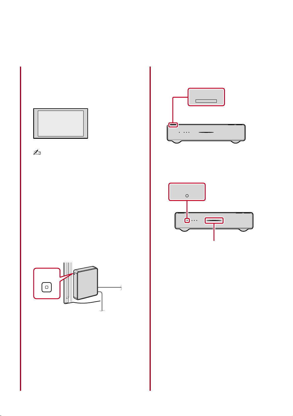
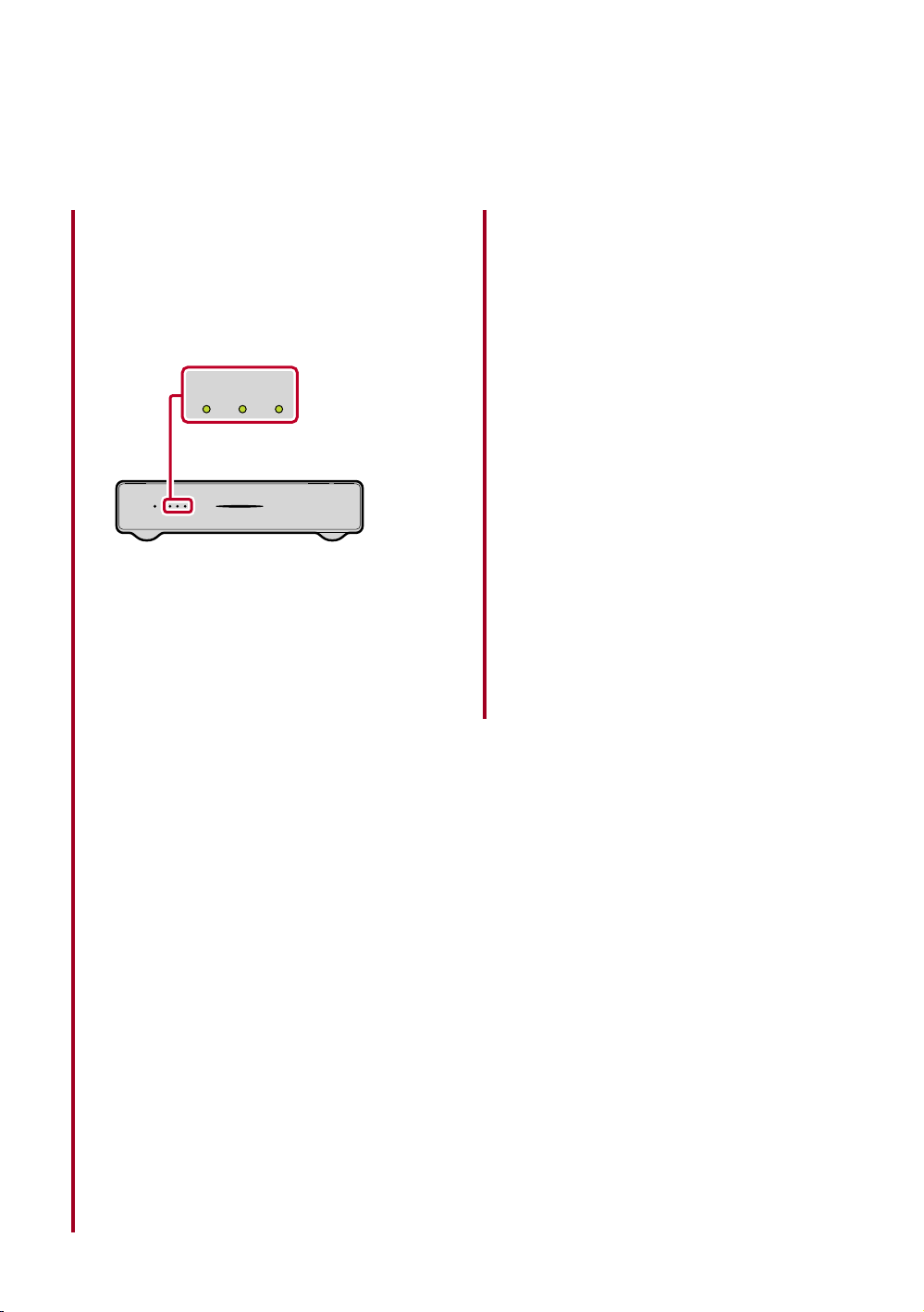
4Verify the Wireless LINK LEVEL.
The LINK LEVEL LEDs located on the front
of the transmitter unit allows you to verify
the Wireless LINK LEVEL between the
transmitter and the receiver units.
LINK LEVEL LED
LINK LEVEL
When the units are establishing a link, the
LINK LEVEL LED blinks.
After the wireless connection is established,
the LED stops blinking.
To ensure good picture quality, make
sure that all three LEDs light up in green,
indicating a good link.
Recommended placement of the receiver
and transmitter units is within 65 feet (20 m)
of each other. If you experience problems
with the LINK LEVEL, removing obstructions
from the path between the units may improve
the LINK LEVEL.
If the Wireless LINK LEVEL is less than three
or the picture is noisy or the sound quality
is diminished, press CONNECT to switch to
another wireless channel.
If you experience problems finding a suitable
LINK LEVEL, see the Troubleshooting
section in the Reference Guide for more
information.
Optimal environment for placement
of the units
Follow the suggestions below to create an
optimal environment for your Wireless Link.
Proper placement of the receiver and transmitter
units will ensure a strong Wireless LINK LEVEL
for superior performance.
• Use one system per room, placing the
transmitter and receiver units for each system
in the same room.
• If you use a 5 GHz WLAN or cordless phone,
place those in a different room.
• Do not place either unit on a metallic rack.
• Place the transmitter unit as high up as
possible.
• Maximum operating distance is approximately
65 feet (20 m), depending on the environment.
• Be sure to keep at least 1 foot (30 cm)
minimum distance between the transmitter and
receiver units.

10
Initial Setup instructions will appear on the
screen when the receiver and transmitter
units are turned on for the first time.
5
Running
Initial Setup
1Press INPUT SELECT on the transmitter
unit to highlight your language choice. Then,
press CONNECT on the transmitter unit to
continue the setup.
Initial Setup
Step 1: Select a language
Highlight a choice by pressing
INPUT SELECT on your
transmitter. Press CONNECT to
continue.
English
Español
F ra n ç a i s
INPUT SELECT
CONNECT
CONNECT button
INPUT SELECT button
• The supplied remote control cannot be used at this
stage.
2Insert batteries into the remote control.
Push to open

11
3On your remote control, press and hold the
IN 1 button. While holding IN 1, press the
RETURN button. Hold both for at least 2
seconds.
Initial Setup
Step2: Activate your remote
c o n t r o l
On your remote, press and
hold IN 1. While holding IN 1,
press RETURN. Hold both
for at least 2 seconds.
Keep your remote control within
10 feet of the transmitter.
AV POWER TV POWER
DISPLAY
POWER
COMPO-
NENT
IN 5
IN 1 IN 2 IN 3 IN 4
TV
HDMI
WIDE
PICTURE
CC
MENU
FREEZE
IN 1
IN 1 button
RETURN button
4Initial Setup is complete.
Initial Setup
Activation complete
To set up IR Blaster, press
SETUP; otherwise press
RETURN to exit.
To use the supplied remote control to operate
equipment connected to the transmitter unit,
proceed to the next page.
• To display Initial Setup again, press CONNECT and
INPUT SELECT on the transmitter unit simultaneously.

12
6 Configuring
the remote control
Configure the IR Blaster to control your
connected equipment using the supplied
remote control.
You can control connected equipment
with your remote by using the IR Blaster
(supplied).
If you chose setup type C, you cannot use the
IR Blaster to control connected equipment.
Exit the Setup menu by pressing SETUP on
the remote control to skip these steps.
1Press SETUP on the remote control to
display the Setup menu.
Setup
IR Blaster
Language
Software Version 1.00.00
HDMI 1
HDMI 2
HDMI 3
HDMI 4
Component
2Press to highlight IR Blaster, and press
. The following screen appears.
Setup/IR Blaster
HDMI 1
HDMI 2
HDMI 3
3Press to highlight an input to configure,
and press .
Setup/IR Blaster/HDMI 1
Category
Maker
Code
Test (Power On/Off)
S a v e a n d E x i t
Open the lid of the
remote control
REC
CONNECT SETUP
TOP MENU
MENU
F1 F2
BD/DVD
REC PAUSE
MUTING JUMP
REC STOP
AV POWER TV POWER
DISPLAY
POWER
COMPO-
NENT
IN 5
IN 1 IN 2 IN 3 IN 4
TV
HDMI
WIDE
PICTURE
CC
MENU
FREEZE
1
4
7
2
5
8
0
3
6
9
ENT
VOLCH
WIRELESS LINK
SETUP
2-8
1

13
4Press to highlight Category (equipment
type), and press .
Select an equipment type from the list, and
press .
Setup/IR Blaster/HDMI 1
Category
Maker
Code
Te s t ( P ow e r
S a v e a n d E x
C a b l e B o x
Satellite
VCR
DV D
B D
Receiver
5
Press to highlight Maker, and press .
Select a manufacturer from the list, and press
.
Setup/IR Blaster/HDMI 1
Category
Maker
Code
Te s t ( P ow e r
S a v e a n d E x
S o n y
L G
Panasonic
Philips
Pioneer
Samsung
6Press to highlight Code, and press .
Select a code from the list, and press .
Setup/IR Blaster/HDMI 1
Category
Maker
Code
Test (Power On/Off)
S a v e a n d E x i t
B D 1
B D 2
B D 3
See page 15 on Reference Guide if your
code is not on the list.
• When more than one code is available for your
manufacturer, start checking from the top of the list for
the code that operates your equipment.
7Press to highlight Test (Power On/Off)
and press .
Test to see if the selected equipment power
turns on and off.
You may need to test more than one code to
find the right code for your equipment.
• If the equipment’s supplied remote control has both
POWER ON and POWER OFF buttons, using Test
(Power On/Off) might not work to test the IR code.
Select Save and Exit then check if any other remote
buttons will operate your equipment.
Setup/IR Blaster/HDMI 1
Category
Maker
Code
Test (Power On/Off)
S a v e a n d E x i t
B D
S o n y
B D 1
8
When you have found the right code, press to
highlight Save and Exit, and press .
Save the setting and exit from the Setup
menu.
Setup/IR Blaster/HDMI 1
Category
Maker
Code
Test (Power On/Off)
S a v e a n d E x i t
B D
S o n y
B D 1
• Do not connect two of the same equipment from
the same manufacturer (Eg. two Sony Blu-ray disc
players), you will not be able to control each equipment
individually.
• To erase the code, select Category, then press to
highlight “----” and press in step 4.

REC
CONNECT SETUP
TOP MENU
MENU
F1 F2
BD/DVD
REC PAUSE
MUTING JUMP
REC STOP
AV POWER TV POWER
DISPLAY
POWER
COMPO-
NENT
IN 5
IN 1 IN 2 IN 3 IN 4
TV
HDMI
WIDE
PICTURE
CC
MENU
FREEZE
1
4
7
2
5
8
0
3
6
9
ENT
VOLCH
WIRELESS LINK
TV
WIDE
PICTURE
FREEZE
MUTING
VOL
TV POWER
MENU
1
4
7
2
5
8
0
3
6
9
ENT
CH
CONNECT SETUP
14
The following buttons are for operating your TV.
Press the TV button before using them.
7
Using
the supplied remote control
Operating your TV
Button Description
TV POWER Press to turn the TV on and off.
TV You must first press the TV function
button to operate the TV.
INPUT Press to select the input of the TV.
PICTURE Press to change the picture mode.
WIDE Press to change the wide mode.
FREEZE Press once to display a frozen image
with the current program in a window.
Press again to return to the current
program.
0-9, ENT Press 0-9 to select a channel; the
channel changes after two seconds,
press ENT to change channels
immediately.
CH +/- Press to scan through channels.
HOME/MENU Press to display the TV Home menu.
VOL+/- Press to adjust the volume.
MUTING Press to mute the sound. Press again or
press VOL+ to restore the sound.
Press the SETUP button to display the Setup
menu if you need to change Language or IR
Blaster settings.
If the Wireless LINK LEVEL is less than three or
the picture is noisy, press CONNECT to switch to
another wireless channel.
• You can use the SETUP or CONNECT buttons when any input is
selected.

REC
CONNECT SETUP
TOP MENU
MENU
F1 F2
BD/DVD
REC PAUSE
MUTING JUMP
REC STOP
AV POWER TV POWER
DISPLAY
POWER
COMPO-
NENT
IN 5
IN 1 IN 2 IN 3 IN 4
TV
HDMI
WIDE
PICTURE
CC
MENU
FREEZE
1
4
7
2
5
8
0
3
6
9
ENT
VOLCH
WIRELESS LINK
COMPO-
NENT
IN 5
IN 1 IN 2 IN 3 IN 4
HDMI
AV POWER
POWER
MENU
15
Operating equipment connected
to the transmitter unit
• You must connect the IR Blaster and complete setup for all connected
equipment before you can operate them.
Button Description
/ Goes to the beginning of the previous/
next title/chapter/scene/track.
/ Replays the scene/briefly fast forwards
the scene.
/ Fast reverses/fast forwards the disc
when pressed during playback.
Plays a disc at normal speed.
Pauses the playback.
Stops the playback.
HOME/MENU Displays menus of selected external
equipment.
Moves the on-screen cursor of selected
external equipment. Press to select/
confirm an item.
1Press POWER to turn the transmitter unit on.
2Press IN 1-4 HDMI or IN 5 COMPONENT to
select the desired input source.
3Press AV POWER to turn on the equipment
connected to the selected input source.
The connected
equipment can be
operated without
aiming the remote
control directly at
the equipment.

For Your Convenience
Please contact Sony Customer Support directly if you:
• Have questions on the use of your module after reading the Startup Guide or Reference Guide
• Experience difficulty operating your module
For United States
http://www.sony.com/tvsupport
or to speak with a support representative: 1-866-918-2485
For Canada
http://www.sony.ca/support
or to speak with a support representative: 1-877-899-SONY (7669)
Sony will work to resolve your questions more quickly than your retailer or place of purchase.
Please Do Not Return the Product to the Store
On-line Registration
United States
http://productregistration.sony.com
Canada
http://www.SonyStyle.ca/registration
Printed in Japan
Other manuals for DMXWL1 - BRAVIA Wireless HD Link
5
Table of contents
Other Sony Network Router manuals