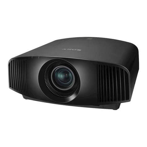
Sony QUALINA 004 User manual


2
3
Owner’s Record
The model and serial numbers are located at
the bottom of the projector. Record these
numbers in the spaces provided below. Refer
to them whenever you call upon your Sony
dealer regarding this product.
Model No.
Serial No.
WARNING
To prevent fire or shock hazard, do not
expose the unit to rain or moisture.
To avoid electrical shock, do not open the
cabinet. Refer servicing to qualified
personnel only.
This symbol is intended to alert the user to
the presence of uninsulated “dangerous
voltage” within the product’s enclosure that
may be of sufficient magnitude to constitute
a risk of electric shock to persons.
This symbol is intended to alert the user to
the presence of important operating and
maintenance (servicing) instructions in the
literature accompanying the appliance.
For customers in the USA
If you have any questions about this product,
you may contact:
Sony Electronics Inc.
Attn: Business Information Center (BIC)
12451 Gateway Boulevard
Ft. Myers, Florida 33913
Telephone No.: 800-686-7669
The number below is for FCC related matters
only.
Declaration of Conformity
Trade Name: SONY
Model No.: Q004-R1
Responsible Party: Sony Electronics Inc.
Address: 680 Kinderkamack Road, Oradell
NJ 07649 U.S.A.
Telephone No.: 201-930-6972
This device complies with Part 15 of the FCC
Rules.
Operation is subject to the following two
conditions: (1) This device may not cause
harmful interference, and (2) this device must
accept any interference received, including
interference that may cause undesired
operation.
This equipment has been tested and found
to comply with the limits for a Class B digital
device, pursuant to Part 15 of the FCC
Rules. These limits are designed to provide
reasonable protection against harmful
interference in a residential installation. This
equipment generates, uses, and can radiate
radio frequency energy and, if not installed
and used in accordance with the instructions,
may cause harmful interference to radio
communications. However, there is no
guarantee that interference will not occur in
a particular installation. If this equipment
does cause harmful interference to radio or
television reception, which can be
determined by turning the equipment off and
on, the user is encouraged to try to correct
the interference by one or more of the
following measures:
- Reorient or relocate the receiving antenna.
- Increase the separation between the
equipment and receiver.
- Connect the equipment into an outlet on a
circuit different from that to which the
receiver is connected.
- Consult the dealer or an experienced
radio/TV technician for help.
You are cautioned that any changes or
modifications not expressly approved in this
manual could void your authority to operate
this equipment.
For customers in Canada
This Class B digital apparatus complies with
Canadian ICES-003.
The socket-outlet should be installed near
the equipment and be easily accessible.
AVERTISSEMENT
Afin d’éviter tout risque d’incendie ou
d’électrocution, n’exposez pas cet appareil
à la pluie ou à l’humidité.
Afin d’éviter tout risque d’électrocution,
n’ouvrez pas le châssis. Confiez l’entretien
uniquement à un personnel qualifié.
Pour les utilisateurs au Canada
Cet appareil numérique de la classe B est
conforme à la norme ICES-003 du Canada.
La prise doit être près de l’appareil et facile
d’accès.
Precautions
On safety
• Check that the operating voltage of your
unit is identical with the voltage of your
local power supply.
• Should any liquid or solid object fall into
the cabinet, unplug the unit and have it
checked by qualified personnel before
operating it further.
• Unplug the unit from the wall outlet if it is
not to be used for several days.
• To disconnect the cord, pull it out by the
plug. Never pull the cord itself.
• The wall outlet should be near the unit and
easily accessible.
• The unit is not disconnected from the AC
power source (mains) as long as it is
connected to the wall outlet, even if the
unit itself has been turned off.
• Do not look into the lens while the lamp is
on.
• Do not place your hand or objects near the
ventilation holes. Air ventilated from the
unit may be hot.
On preventing internal heat build-up
After you turn off the power with the ?/1
(on/standby) switch, do not disconnect the
unit from the wall outlet while the cooling fan
is still running.
Caution
The projector is equipped with intake
ventilation holes and exhaust ventilation
holes. Do not block or place anything near
these holes as internal heat build-up may
occur, causing picture degradation or
damage to the projector.
On repacking
Save the original shipping carton and
packing material; they will come in handy if
you ever have to ship your unit. For
maximum protection, repack your unit as it
was originally packed at the factory.

4
5
Adjustments and Settings Using the Menu
Using the menu...................................................................................................................... 30
PICTURE SETTING menu ............................................................................................... 32
PICTURE MODE................................................................................................. 32
ADJUST PICTURE ............................................................................................ 33
INPUT SETTING menu...................................................................................................... 36
ADJUST SIGNAL................................................................................................ 36
AUTO WIDE SETTING .................................................................................... 37
SET SETTING menu............................................................................................................ 46
MENU SETTING menu...................................................................................................... 48
INSTALL SETTING menu ................................................................................................. 49
INFORMATION menu ......................................................................................................... 51
ImageDirector.......................................................................................................................... 52
Features ................................................................................................................... 52
Operating system environment for ImageDirector....................... 52
Installing ImageDirector................................................................................. 53
Uninstalling ImageDirector........................................................................... 54
Table of Contents
Overview
Bring out the fascination of a movie theater ..........................................................8
Identification of parts ......................................................................................................... 18
Projecting Images
Projecting images................................................................................................................. 26
To turn off the power ....................................................................................... 29
Projecting ImagesOverview
Adjustments and
Settings Using
the Menu
Installation/
Connections
Operations Using
the Network Maintenance
Additional
Information

6
7
Installation/Connections
Notes for installation........................................................................................................... 56
Unsuitable installation..................................................................................... 56
Improper use......................................................................................................... 57
Installing the projector....................................................................................................... 58
Floor installation ................................................................................................. 58
Ceiling installation ............................................................................................. 60
Connections............................................................................................................................. 64
Operations Using the Network
Operating the projector from a computer ............................................................ 68
Accessing the projector from a computer......................................... 68
Checking the status of the projector..................................................... 68
Controlling the projector from a computer........................................ 69
Setting up the projector................................................................................. 69
Maintenance
Lamp and filter maintenance......................................................................................... 74
Replacing the lamp/air filter........................................................................ 74
Note for maintaining good performance .............................................................. 75
Troubleshooting ..................................................................................................................... 76
Power ........................................................................................................................ 76
Picture....................................................................................................................... 77
Remote..................................................................................................................... 78
Caution messages ............................................................................................ 78
Warning messages ........................................................................................... 79
Information panel display ............................................................................. 80
ImageDirector....................................................................................................... 81
Additional Information
Warranty card and after-sale services..................................................................... 82
Specifications.......................................................................................................................... 83
Dimensions ............................................................................................................ 86
Index ............................................................................................................................................. 88
The pictures used as examples in this “Owner’s Guide” are still images,
and are not actual images using this projector.
Projecting ImagesOverview
Adjustments and
Settings Using
the Menu
Installation/
Connections
Operations Using
the Network Maintenance
Additional
Information
Table of Contents (continued)

8
9
Bring out the fascination of a movie theater
Imagine how it feels like to watch a movie in a movie theater ——
the large screen, the velvety quality of the film, the natural and
vivid color.
Sony’s goal in designing this projector is to reproduce the
“emotional space” of a movie theater.
Sony achieved this by rethinking all steps of projector design
from the bottom up, and developed the technology that is fully
assimilated to re-create superb picture quality and naturally rich
color gradation.
Technologies used to
establish the “emotional space”
The projection lens
excels in creating sharp,
focused images with
high contrast.
The carefully designed
cooling mechanism is
absolutely silent.
The Silicon X-tal
Reflective Display
reproduces pictures
accurately from Full HD
(high definition) sources.
A light source that
borders on sunlight.
Pure xenon lamp
Cooling mechanism
Full HD SXRD panel
Carl Zeiss lens
Overview
Overview

10
11
Capturing the velvety texture of films
— Full HD SXRD panel
Delicate image rendition without
the “Screen Door Effect”
One of the most difficult image factors to
reproduce is smoothness. Most projectors
provide video images that look as though
they were shown through a screen door.
This is called the “Screen Door Effect” — an
effect caused by the fact that the image is an
artifact of pixel construction.
When fixed-pixel projection devices display
an extended picture, you notice the grainy
“mesh” effect on the picture. This is because
a black matrix, like the lattice pattern of a
screen door, covers the pixel area to prevent
the light source from shining through to the
control electronics, which surround each
pixel.
The reflective liquid crystal display panel
“SXRD (Silicon X-tal Reflective Display)”
installed in this projector places the control
electronics behind each pixel as a reflective
device. Because of this, the space between
each pixel narrows by 0.35 µm, the opening
increases by 92 % of the LCD panel, and the
lattice part of the “screen door” decreases
by 8 %, which helps achieve a high open
area ratio.
Illustration of the “mesh” effect
— A comparison using the same screen image
SXRD
1920×1080 dot,
92% open area ratio
Conventional
transmissive LCD
1366×768 dot,
50% open area ratio
The space between each
pixel is narrow and the pixel
pitch is small.
“SXRD” is a trademark of Sony Corporation.
Smooth rendering of fast-moving
images
Conventional projectors often display swift
images with lasting after-effects that destroy
sharpness because the LCD displays cannot
respond fast enough to switching signals.
This projector, utilizing SXRD technology,
makes the very rapid 5 milli-second response
time a reality. This improvement enhances
crisp and vivid image reproduction, even
from video sources containing fast-moving
images.
Excellent contrast from white to
black— 12-bit panel driver
The 12-bit panel driver in this projector, used
at the final stage of digital signal processing,
compensates with a high degree of accuracy,
ensuring the accurate delivery of the high
2000:1 contrast level. As a result, a linear
contrast from white to black, with intense,
velvety darkness is successfully reproduced.
Authentic reproduction of high
resolution sources
An SXRD panel has about 2,000,000 enabled
square pixels (1920 × 1080 pixels), about
twice as many as other high-end projectors.
For this to be achieved, both the size of each
individual pixel and the space between pixels
has been minimized to a pitch of 9 µm within
an image area measuring a mere 0.78 inches
across. The projector authentically
reproduces breathtaking pictures from HD
(High Definition) signal sources, which can
be enjoyed free of the “mesh” effect.
Superb high-contrast black
The SXRD panel offers high quality contrast.
The thin liquid crystal cell gap, narrow
inter-pixel spacing, and “Vertically Aligned
Liquid Crystal” materials, whereby the liquid
crystal molecules are aligned perpendicular
to the cell substrates, develop a high panel
contrast of 3000:1. Combining panels with
good driving voltages and high quality optical
properties that also provide a contrast of
3000:1, this projector offers a high contrast
level of 2000:1. The 2000:1 ratio means that
black is 1/2000 as bright as white.
Also, the optical unit and drive circuit make
full use of the developed dynamic contrast
range. This projector represents an
approximately 2 to 3 fold increase in contrast
over conventional projector contrast levels,
achieving the “coal black” quality available
only in films. These advances have facilitated
the achievement of outstanding cinematic
quality, providing the ultimate movie-viewing
experience at home.
Difference between 12-bit
and 10-bit correction
Input
Output
10-bit
correction
12-bit
correction
Overview

12
13
Perfect rendition of natural colors
Reproducing bottomless whites, spectacular reds
— Pure xenon lamp
Reproducing the brightness of clear whites and reds was a
difficult matter for projectors because of the UHP lamp
system (ultra high pressure mercury lamp), a standard light
source built into conventional LCD projectors. Each RGB
brightness level that a UHP lamp provides is different, as
indicated by the gray line on the following diagram. The red (R)
level is very much lower than that of green (G) and blue (B),
thus failing to produce a clear red that in turn affects various
other colors.
The pure xenon lamp system, utilized by this projector in
place of the UHP lamp, gives a light beam very similar to
sunlight. Because of its flat spectral characteristics, the beam
is used for critical applications that need accurate color
reproduction, such as solar simulators, fiberscopes, etc. The
most common application of the pure xenon lamp system is
in the cinematographs of movie theaters.
Pure xenon lamp
Spectral characteristics of a pure xenon lamp,
sunlight, and a UHP lamp
Brightness of the light
Wave length (nm) UHP lamp
Sunlight
Pure xenon lamp
400 450 500 550 600 650 700
As shown in the diagram below, this
projector incorporates a design that keeps
the physical distance between the lamp and
each panel of red (R), green (G) and blue (B)
equal, which makes it very effective at
reproducing pictures evenly colored to the
four corners of the screen.
Highly-uniform color reproduction
over the entire screen
— Isometric illumination system
In previous projectors, one of the physical
distances between the lamp and each panel
of red (R), green (G) and blue (B) had to differ
from the other two, which caused color
heterogeneity. This color heterogeneity was
electrically and optically compensated for,
but not completely eliminated.
The beauty of real black
— Cinema Black Pro
Truly accurate black color reproduction is
necessary for a movie to be considered
visually beautiful. In addition to the existing
electric power regulation of the lamp, this
projector achieves this black color by utilizing
an optical iris that has an electric diaphragm
on the lighting path.
By controlling the iris (which decreases the
light intensity and makes a thinner beam) the
contrast is emphasized and the black level is
enhanced. Furthermore, this feature enables
the adjustment of the light volume, ensuring
the optimum brightness for the screen size,
not only for a large screen that uses high
volume, but also for a small screen.
Optical iris
High light volume
Low contrast
Low light volume
High contrast
When the optical iris
increases the light intensity
When the optical iris
decreases the light intensity
Diagram of the isometric illumination system
Lamp Lamp
Red (R) SXRD
Blue (B) SXRD
Green (G)
SXRD
Lamp Projection lens
Red (R) lighting path
Green (G) lighting path
Blue (B) lighting path
Equal distance
Overview

14
15
Short focal lens
VPLL-ZP310
Middle focal lens
VPLL-ZP400
Long focal lens
VPLL-ZP550
Lens diagram
Uses ED glass-forming
materials.
The Carl Zeiss lens on the projector delivers
exact resolution and projection of pictures
with pixels of 9 µm. The lens, consisting of
15 elements in 13 groups embedded in a
machined aluminum cam, is made of glass
covered with a full multi-AR (Anti-Reflection)
coating. These lenses have enormously high
transmission capabilities. ED (Extra-low
Dispersion) glass-forming materials are
incorporated into 6 of 15 elements for the
short focal lens, or 5 for the middle or long
focal lens. These innovations have achieved
high quality imaging by preventing colors
from blending.
Every lens is evaluated for performance by
the MTF (Modulation Transfer Function) and
have demonstrated a uniform performance
level. The name and serial number that Carl
Zeiss assigns to each Zeiss lens are proof of
the quality of the products.
Exquisite detail
— Carl Zeiss lens
Internal structure
MTF Diagrams
The Modulation Transfer Function (MTF) is an objective
method used to clearly represent and evaluate the
performance of lenses. In the diagrams, the horizontal
axis gives the real image height in mm (the distance
Short focal lens VPLL-ZP310
Middle focal lens VPLL-ZP400
Long focal lens VPLL-ZP550
Spatial frequency 56 lp/mm (sagittal)
Spatial frequency 56 lp/mm (meridional)
Spatial frequency 80 lp/mm (sagittal)
Spatial frequency 80 lp/mm (meridional)
f=25mm f=33mm
MTF
Real image height (mm)
f=32mm f=45mm
MTF
f=44mm f=61mm
MTF
between the center and any corner of the image), and
the vertical axis gives the contrast when the spatial
frequency is 56 lp/mm and 80 lp/mm. Each lens for this
projector is measured for high resolution and contrast.
Real image height (mm)
Real image height (mm) Real image height (mm)
Real image height (mm)
Overview

16
17
Enjoy the silence
This projector ventilates the heat of the
power supply and lamp as shown in the
diagram above. The flow of air is designed
for low resistance to let the intense heat of
the pure xenon lamp dissipate quickly and
deaden the noise from the fans.
The intake air from ventilation holes cools
down the power supply circuit first, then is
blown onto the lamp.
To ensure virtual silence, this projector uses
closed air ducts from the fans to the lamp,
giving full consideration to aerodynamics.
By installing the two large fans in the inner
part of the unit, the driving noise of the fans
does not escape from the cabinet. Wind
noise is also reduced by decreasing the
revolution of the fan blades.
Flow of air
Ventilation holes
(exhaust)
Fan
Side ventilation
holes (intake)
Fan
Front ventilation
holes (intake)
The calorific value of the pure xenon lamp is
very high, reaching hundreds of degrees
without cooling off. To dissipate the heat, the
projector is provided with an efficient cooling
structure in which heat sinks with a radiation
coating are installed around the lamp. This
unique configuration is made of extruded
aluminum.
Heat sink with a radiation coating
A 5 mm thick foamed aluminum panel is
located on the top of the cabinet. This
material, used in building construction,
reduces fan noise to a bare minimum,
ensuring that you will only hear the sound
from your audio system.
This projector focuses on achieving silent
operation as a natural progression of the
pursuit for high picture quality. This result is
a nearly non-existent noise level, quieter than
a whispery voice.
Previously, realistic high quality visuals and
smooth motion was available only in movie
theaters. You can now enjoy them in the
comfort of your home.
5 mm foamed aluminum panel
Overview

18
19
Front/Top
Rear/Bottom
Identification of parts
1 2
4
5
6
q;
qa
7
8
qd
9
qs
3
Rear/Bottom
7 Rear remote detector (SIRCS receiver)
8 Ventilation holes (exhaust)
9 Ventilation holes (intake)/Air filter
0 Adjusters
When a picture is projected on an exterior
screen, adjust the picture using these
adjusters. The picture moves up as you turn
them clockwise and moves down as you turn
them counterclockwise.
qa Connector panel (Right side)
For details, see “Connector panel” on page
66.
qs Connector panel (Left side)
For details, see “Connector panel” on page
64.
qd AC IN socket
Connect the AC power cord. To avoid
unplugging the AC power cord accidentally,
attach the supplied plug holder.
Plug holder
Notes
• Make sure that the AC power cord is connected
properly.
• Attach the plug holder to avoid unplugging the AC
power cord accidentally. Also, the plug holder
prevents the AC power cord from becoming clogged
with dust.
• For safety, use the AC power cord supplied with the
unit.
continued
Front/Top
1 Front remote detector (SIRCS receiver)
2 Lens/Lens protector
3 Ventilation holes
Note on ventilation holes (intake/exhaust)
• Do not place anything near the ventilation holes as
this may cause internal heat build-up.
Placing your hand near the ventilation holes may
cause burn injuries.
4 Information panel display
Displays the status of the projector.
5 Control panel
A control panel is located in the unit. You
can open the control panel by pressing the
button beside it.
For details, see “Control panel” on page 20.
6 Pure xenon lamp
Control panel
Button
Overview

20 21
Control panel
Identification of parts (continued)
6 87
2 43
5
1
Location of the control panel
The control panel is located
on the rear of the projector
as shown below.
1 ?/1 (on/standby) button
Turns the projector on when the projector is
in the standby mode.
To turn off the projector, press the ?/1
button twice or press and hold the ?/1
button for about one second according to
the indications on the screen.
For details on steps for turning off the power,
see “To turn off the power” on page 29.
2 FOCUS button
Adjusts the picture focus using the arrow
buttons.
3 ZOOM button
Adjusts the size of the picture using the
arrow buttons.
4 SHIFT button
Adjusts the vertical position of the picture
using the arrow buttons.
5
INPUT button
Selects the input signal. Each time you press
the button, the input signal switches
cyclically as follows:
INPUT-A INPUT-B DVI
S-VIDEO VIDEO HDMI
6 MENU button
Displays the on-screen menu. Press again to
clear the menu.
7 M/m/</, (arrow) buttons
Select a menu or make various adjustments.
8 ENTER button
Enters the settings of items in the menu.
continued
Overview

22
23
1 PICTURE MUTING button
Turns off the picture. Press
again to restore the picture.
2 INPUT buttons
Select the input signal.
VIDEO:
For the video signal of
equipment connected to the
projector’s VIDEO jack.
S VIDEO:
For the video signal of
equipment connected to the
projector’s S VIDEO jack.
A:
For the video signal of
equipment connected to the
projector’s INPUT A
connectors.
B:
For the video signal of
equipment connected to the
projector’s INPUT B
connectors.
DVI:
For the video signal of
equipment connected to the
projector’s DVI-D connectors.
HDMI:
For the video signal of
equipment connected to the
projector’s HDMI connectors.
3 COLOR SPACE button
Each time you press this
button, the “Color Space”
setting changes between
“Normal” and “Wide.”
Identification of parts (continued)
5
6
7
1
3
8
qd
qs
q;
qa
Remote
2
9
Indicators on the buttons light up if you shake or tilt the
remote. The indicators are turned off automatically if you
do not move the remote for about 20 seconds.
Buttons which have the same names as those on the
control panel function identically.
ql
qh
qk
qj
qg
qf
4
w;
qf IRIS CONT button
Emphasizes the contrast
during projection. Each time
you press this button, the “Iris
Control” setting changes
cyclically as follows: “Off,” “1,”
“2.”
qg MENU button
Displays the menu.
qh ENTER button
Enters the settings of items
in the menu.
qj COLOR +/− button
Adjusts the intensity of the
color. The intensity increases
as you press the + button and
decreases as you press the –
button.
qk CONTRAST +/− button
Adjusts the contrast. The
contrast increases as you
press the + button and
decreases as you press the –
button.
ql BRIGHT +/− button
Adjusts the brightness. The
brightness becomes brighter
as you press the + button and
darker as you press the –
button.
w; CONTROL S OUT jack
(minijack)
Connect to the CONTROL S
IN jack on the projector when
using it as a wired remote.
Even when you use the remote
as a wired remote, batteries
must be inserted in the
remote.
continued
4 GAMMA button
Selects the projector’s gamma
value from settings you made
using “ImageDirector” (see
page 52). Each time you press
this button, the “Gamma
Correction” setting changes
cyclically as follows: “Off,”
“Gamma1,” “Gamma2,”
“Gamma3.”
5 M/m/</, (arrow)
buttons
6 RESET button
Resets items that have been
adjusted to their factory preset
values. The button activates
while the menu is displayed or
the items are adjusted
(displayed).
7 PICTURE MODE buttons
DYNAMIC:
Enhances picture contrast and
sharpness.
STANDARD:
Recommended for normal
viewing conditions. Select this
if you encounter roughness
when viewing the picture with
“Dynamic.”
CINEMA:
Recommended when viewing
a movie.
USER 1~3:
Adjust the quality of the
picture to suit your taste and
store the settings. For details,
see “PICTURE MODE” in the
PICTURE SETTING menu on
page 32.
8 WIDE MODE button
Each time you press this
button, the “Wide Mode”
setting changes cyclically as
follows: “Full,” “Normal,” “Wide
Zoom,” “Zoom,” “Subtitle” (see
page 40).
9 Infrared transmitter
q; ?/1 button
Turns the projector on when
the projector is in standby
mode. To turn off the
projector, press the ?/1
button twice or press and hold
the ?/1 button for about one
second according to the
indications on the screen.
qa COLOR TEMP button
Each time you press this
button, the “Color Temp”
setting changes cyclically as
follows: “High,” “Middle,”
“Low,” “Custom1,” “Custom2,”
“Custom3.”
For details, see page 34.
qs SOURCE DIRECT button
Reproduces a faithful picture
from the HD (High Definition)
input signal.
qd LENS CONT button
Each time you press this
button, the “Lens Control”
setting changes cyclically as
follows: “Focus,” “Zoom,”
“Shift.” You can adjust each
setting by pressing the arrow
buttons.
Overview

24
25
Inserting batteries
1 Turn the screw counterclockwise using a
coin, etc. to open the lid.
2 Insert the four size AAA (R03) batteries
(supplied), taking care to match the
polarities as shown below.
Identification of parts (continued)
3 Replace the lid, then turn the screw
clockwise to lock the lid.
Be sure to insert
the batteries from
the # side first.
Turn clockwise.
Notes on batteries
• Make sure that the battery polarity (orientation) is
correct when inserting batteries.
• Do not mix an old battery with a new one, or mix
different types of batteries.
• If you do not intend to use the remote for a long
time, remove the batteries to avoid damage from
battery leakage. If batteries have leaked, remove
them, wipe the battery compartment dry and
replace the batteries with new ones.
Notes on remote operation
• Make sure that there is nothing between the remote
and the remote detector on the projector to obstruct
the infrared beam.
• The operating range is limited. The shorter the
distance between the remote and the projector is,
the wider the angle within which the remote can
control the projector.
• Even when you use the remote as a wired remote,
batteries must be inserted in the remote.
Turn
counterclockwise.
Overview

26
27
Projecting images
1 Press the ?/1 button on the remote or
on the control panel to turn the projector
on.
2 Turn on any equipment connected to the
projector.
3 Press the INPUT button to select the
input source.
INPUT-A Component equipment
connected to the INPUT A
connector on the projector
INPUT-B Equipment connected to the
INPUT B connector on the
projector
DVI Video equipment connected
to DVI-D connector on
projector
HDMI Video equipment connected
to HDMI connector on the
projector
VIDEO Video equipment connected
to the VIDEO (VIDEO IN) jack
on the projector
S-VIDEO Video equipment connected
to the S VIDEO (VIDEO IN)
jack on the projector
4 Adjust the display settings below.
•
Press the LENS CONT button on the
remote repeatedly or the FOCUS
button on the control panel to turn on
the FOCUS setting display. Then, press
the arrow buttons to adjust the focus.
•
Press the LENS CONT button on the
remote repeatedly or the ZOOM button
on the control panel to turn on the
ZOOM setting display. Then, press the
arrow buttons to adjust the size of the
picture.
•
Press the LENS CONT button on the
remote repeatedly or the SHIFT button
on the control panel to turn on the
SHIFT setting display. Then, press the
arrow buttons to adjust the vertical
position of the picture.
Note
• Looking into the lens when the projector is
projecting an image may cause injury to your eyes.
To turn off the picture
Press the PICTURE MUTING button on the
remote. To restore the picture, press the
PICTURE MUTING button again.
continued
PICTURE
MUTING
button
?/1
button
INPUT
buttons
LENS
CONT
button
Rear
Remote
Remote detector
Remote detector
Front
Control panel
INPUT button
?/1
button
ZOOM
button
FOCUS
button
SHIFT
button
Projecting images
Projecting Images

28
29
Selecting the screen projection mode
You can enjoy various screen projection
modes according to the video signal
received. For details on the available video
signals, see page 42.
For details on operating the menu screen,
see “Using the menu” on page 30.
1 Press the MENU button.
The menu display appears.
2 Press the M or m button to select the
INPUT SETTING menu, then press the ,
or ENTER button.
3 Press the M or m button to select “Wide
Mode,” then press the , or ENTER
button.
4 Press the M or m button to select the
desired screen projection mode, then
press the < or ENTER button.
Notes on changing the screen projection mode
This projector provides you with various choices of
screen projection mode. When selecting the screen
projection mode, consider the following:
• Selecting a screen projection mode may provide a
different look from that of the original image.
• If the projector is used for profit or for public
viewing, modifying the original picture by switching
aspects may constitute an infringement of the rights
of authors or producers that are legally protected by
copyright laws.
Projecting images (continued)
To turn off the power
1 Press the ?/1 button on the remote or
control panel.
“Power OFF?” appears.
Note
• The message disappears if you press any button
except the ?/1 button on the remote or on the
control panel, or if you do not press any button
for 5 seconds.
2 Press the ?/1 button on the remote or on
the control panel again.
The fan runs for several seconds to
reduce internal heat build-up.
3 Confirm that the ?/1 indicator light is lit in
red.
If you operate the projector without
viewing the screen
If you operate the projector from a location
where you cannot view the on-screen
message, you can also turn off the power by
holding the ?/1 button for about one second.
Note
• The internal circuitry of the Direct Power On/Off
function may drive the fan for a short time even after
the ?/1 button is pressed and nothing is displayed
on the information panel display.
Direct Power On/Off function
If you use a circuit breaker to turn the power
for the entire system on and off, set the
direct power on function to “On” (see page
50). When you turn the power off, you can
also just unplug the power cord without
pressing the ?/1 button. The internal circuitry
will cause the fan to automatically operate
for a short while, even after the power cord
is removed. However, if the unit has been on
for less than 15 minutes, follow the
procedure for turning off the power as
described in “To turn off the power.”
Projecting images

30
31
3 Use the M or m button to select an item,
then press the , or ENTER button.
The settings appear in a pop-up window
or are displayed in the next level.
In a pop-up window
Menus Settings
In the next level
Menus Settings
The projector is equipped with an on-screen
menu for making various adjustments and
settings.
You can select the language to be used in
the menu.
1 Press the MENU button.
The menu display appears.
The currently selected menu is shown in
yellow.
Menus
2 Use the M or m button to select a menu,
then press the , or ENTER button
The selected menu appears.
Using the menu
4 Select an item.
Use the M or m button to select an item,
then press the , or ENTER button.
5 Adjust an item.
• When changing the adjustment level:
To increase the value, press the M or
, button.
To decrease the value, press the m or
< button.
Press the ENTER button to enter the
value and return the previous screen.
• When changing the setting:
Press the M or m button to change the
setting.
Press the < or ENTER button to enter
the value and return the previous
screen.
For details on setting individual items,
see the relevant menu pages.
To turn off the menu display
Press the MENU button.
The menu display disappears automatically if
no button is pressed for about one minute.
To reset items that have been adjusted
Press the RESET button on the remote.
“Complete!” appears and the settings
displayed on the screen will be reset to their
factory preset values.
Items that can be reset are:
• “Contrast,”“Brightness,”“Color,”“Hue,” and
“Sharpness,” in the PICTURE SETTING
menu.
• “Dot Phase,”“H Size,”“Shift,”“V Position,”
and “Title Area” in the INPUT SETTING
menu.
• “V Keystone” in the INSTALL SETTING
menu.
Retention of the settings
The settings are automatically stored in the
projector’s memory.
Adjustments and
Settings Using
the Menu
Adjustments and
Settings Using
the Menu

32
33
PICTURE SETTING menu
PICTURE MODE
You can select the picture mode that best
suits the type of program or your
room’s conditions.
Dynamic:
Select this for enhanced picture contrast and
sharpness.
Standard:
Recommended for normal viewing conditions
in your home. Select this if you encounter
roughness when viewing the picture with
“Dynamic.”
Cinema:
Select this for a soft, film-like picture.
User1, User2, User3:
Adjust the quality of the picture to suit your
taste. The settings will be stored in a
pre-selected memory area of the projector.
Press one of the User1, 2, or 3 buttons, then
adjust the picture using the menus.
To view the picture with the adjusted picture
quality, press the respective button.
To store the settings
1 Select “User1,” “User2,” or “User3.”
2 Select and adjust the “ADJUST PICTURE”
items. You can also select “Dynamic,”
“Standard,” or “Cinema” mode and adjust
the “ADJUST PICTURE” items for these
modes as well. To reset the items to the
factory setting, press the RESET button
on the remote.
ADJUST PICTURE
The ADJUST PICTURE menu is used for
adjusting the picture.
Items that cannot be adjusted for a particular
input signal do not appear in the menu.
Contrast
Adjusts the picture contrast.
The higher the setting, the greater the
contrast.
The lower the setting, the lower the contrast.
Brightness
Adjusts the picture brightness.
The higher the setting, the brighter the
picture.
The lower the setting, the darker the picture.
Color
Adjusts color intensity.
The higher the setting, the greater the
intensity.
The lower the setting, the lower the intensity.
Hue
Adjusts color tones.
The higher the setting, the more greenish the
picture becomes.
The lower the setting, the more purplish the
picture becomes.
Sharpness
Adjusts the picture sharpness.
The higher the setting, the sharper the
picture.
The lower the setting, the softer the picture.
Black Level Adj.
Select “Off,” “Low,” or “High,” depending on
the source signal, to produce a bolder,
dynamic picture.
Note
• You cannot adjust “Black Level Adj.” when input
preset memory No.5, 45, or 49 (page 43) is input
and “Source Direct” is set to “On.”
Gamma Correction
Select “Off (no gamma correction),”
“Gamma1,”“Gamma2,” or “Gamma3.”
You can set and store your favorite tone to
“Gamma1,” “Gamma2,” and “Gamma3”
using “ImageDirector” (see page 52).
Note
• You cannot adjust “Gamma Correction” when input
preset memory No.5, 45, or 49 (page 43) is input
and “Source Direct” is set to “On.”
continued
Adjustments and
Settings Using
the Menu

34
35
PICTURE SETTING menu
(continued)
Color Temp
Adjusts the color temperature.
High:
Select to make the whites bluish.
Middle:
Select to set the color temperature between
“High” and “Low.”
Low:
Select to make the whites reddish.
Custom1, Custom2, Custom3:
Adjust the color temperature to suit your
taste. The settings will be stored in a
pre-selected memory area of the projector.
I/P Mode
Smooths out video images that look rougher
as the size increases.
DRC Progressive:
Select to convert an interlace format video
signal to a progressive format.
DDE Progressive:
Select to convert an interlace format HD (high
definition) signal to a progressive format.
DDE Film:
Select to reproduce 2-3 Pull-Down film
sources with smooth picture movement.
When the video signal with a format other
than the 2-3 Pull-Down format is input, “DDE
Progressive” is selected automatically.
DRC High Dens.:
Select to double the number of video signal
scanning lines and the number of horizontal
pixels to quadruple picture image density.
When you press the , or ENTER button
while “DRC High Dens.” is selected, the DRC
Palette display appears.
DRC Palette:
Adjust the “Reality” and “Clarity” of a picture
to suit your taste. These items are adjustable
only when “DRC High Dens.” or “DRC
Progressive” is selected.
To increase the value for “Clarity,” press the
, button.
To decrease the value for “Clarity,” press the
< button.
To increase the value for “Reality,” press the
M button.
To decrease the value for “Reality,” press the
m button.
Cinema Black Pro
Emphasizes the black color.
Iris Control:
Off: Normal contrast.
1: Select to set the contrast level between
“2” and “Off.”
2: Select to enhance the black by
emphasizing the contrast.
Lamp Control:
High: Normal wattage.
Low: Select to enhance the black by
reducing the lamp wattage.
Input signals and adjustable items
Item Input signal
Video or S video Component Video GBR Computer
Contrast a a a a
Brightness a a a a
Color a
(except for
black-and-white)
a a
Hue aaa
(NTSC 3.58 /4.43
only, except for
black-and-white)
Sharpness aaa
Black Level Adj.* aaa
Gamma Correction* a a a a
Color Temp. a a a a
I/P Mode** a a
(input signal preset
memory No.1, 2, 3,
4, 5, 45, 49 only)
a
(input signal preset
memory No.1, 2, 3,
4, 5, 45, 49 only)
Cinema
Black
Pro
Iris
Control a a a a
Lamp
Control a a a a
a: Adjustable/can be set : Not adjustable/can not be set
* You cannot adjust “Black Level Adj.” and “Gamma
Correction” when input signal preset memory No. 5,
45, or 49 (page 43) is input and “Source Direct” is
set to “On.”
** You cannot select “DDE Progressive” when input
signal preset memory No. 1, 2, 3, or 4 (page 43) is
input. You cannot select “DRC High Dens.” or “DRC
Progressive” when input signal preset memory No. 5,
45, or 49 (page 43) is input.
Adjustments and
Settings Using
the Menu

36
37
INPUT SETTING menu
ADJUST SIGNAL
The INPUT SETTING menu is used to adjust
the input signal.
Items that cannot be adjusted for a particular
input signal do not appear in the menu.
Example: When a computer signal is input.
Dot Phase
Adjusts the dot phase of the panel and the
computer signal input from the INPUT B
connector.
Adjust the picture to the point where it looks
clearest.
H Size
Adjusts the horizontal size of the picture
input from the INPUT A/B connector.
The higher the setting, the larger the
horizontal size of the picture. The lower the
setting, the smaller the horizontal size of the
picture. Adjust the setting according to the
number of dots of the input signal. For
details on a suitable value for the preset
signals, see page 43.
Shift
Adjusts the position of the picture input from
the INPUT A/B connectors.
Use the < or , button for “H (the
horizontal position of the picture)” and the M
or m button for “V (the vertical position of the
picture).”
As the setting for “H” increases, the picture
moves to the right, and as the setting
decreases, the picture moves to the left.
As the setting for “V” increases, the picture
moves up, and as the setting decreases, the
picture moves down.
AUTO WIDE SETTING
When set to “2,” the most appropriate screen
projection mode is selected automatically
according to the signal being input and
displays the picture to fill a 16:9 screen.
Example: When a video signal is input.
Auto Wide
Off:
Select to display any picture in the currently
selected wide screen projection mode.
1:
Select to display a picture containing an
aspect ratio signal* with the original aspect
ratio.
2:
Select to display a picture with the most
appropriate screen projection mode
regardless of the aspect ratio signal.
4:3 Default
Select “Wide Zoom” or “Normal” to display a
picture in either mode when a normal 4:3
aspect ratio picture is input and the “Auto
Wide” is set to “2.”
* An aspect ratio signal lets a TV, etc.
reproduce a picture with its original ratio.
This projector can handle images such as
video camera pictures, DVD movies, etc.
with an aspect ratio signal included in the
data (e.g. ID-1, S2).
continued
Adjustments and
Settings Using
the Menu

38
39
INPUT SETTING menu (continued)
You can also select the desired screen
projection mode manually. Each time you
press the WIDE MODE button on the remote,
the “Wide Mode” setting changes cyclically
as follows: “Full,” “Normal,” “Wide Zoom,”
“Zoom,” “Subtitle.”
Screen projection mode when “Auto Wide 1” or “Auto Wide 2” is set
(depending on the type of picture)
Type of picture Screen projection mode
Auto Wide 1 Auto Wide 2
Normal TV broadcast The image is displayed
according to the screen
projection mode selected
with the WIDE MODE
button or with “Wide
Mode” in the INPUT
SETTING menu.
“Wide Zoom” or
“Normal”*
TV broadcast with a signal containing an
aspect ratio of 4:3 (“Normal”)
“Normal” “Wide Zoom” or
“Normal”*
Wide-format movie with a subtitle area on
the picture
The image is displayed
according to the screen
projection mode selected
with the WIDE MODE
button or with “Wide
Mode” in the INPUT
SETTING menu.
“Zoom”
Wide-format movie with a subtitle area
out of the picture
The image is displayed
according to the screen
projection mode selected
with the WIDE MODE
button or with “Wide
Mode” in the INPUT
SETTING menu.
“Subtitle”
Video camera picture, DVD movie, etc.
with an ID-1 or S2 signal containing an
aspect ratio of 16:9 (“Zoom” or “Full”)
“Zoom” or
“Full”
“Zoom” or
“Full”
Video camera picture, DVD movie, etc.
with an ID-1 or S2 signal containing an
aspect ratio of 4:3 (“Normal”)
“Normal” “Wide Zoom” or
“Normal”*
* This depends on the setting of “4:3 Default” in “AUTO WIDE SETTING.”
If no aspect ratio signal is input when “Auto
Wide” is set to “1,” black bands may appear
on the perimeter of the screen or a part of
the picture may not be displayed according
to the screen projection mode you selected
manually.
About the screen projection mode
• Soon after being changed using the WIDE
MODE button, the picture may appear in a
screen projection mode different from the
one shown in the chart on page 38.
• When “Auto Wide” is set to “1” or “2,” it
keep working even though you press the
WIDE MODE button only once. If you press
the WIDE MODE button more than once,
you can select the desired projection
mode.
- If the signal contains an aspect ratio
signal, the screen projection mode
changes according to the aspect ratio
signal in the picture received.
- If the signal does not contain an aspect
ratio signal, the screen projection mode
does not change even though “Auto
Wide” is set to “2.” However, the “Auto
Wide” settings will be enabled again if
you change the channel, the input signal,
or turn the projector off and on.
If the screen projection mode changes
spontaneously when “Auto Wide” is set to “1”
or “2”
• The projector automatically selects the
most appropriate screen projection mode
according to the aspect ratio of the input
signal.
• When commercials come on or a program
changes, etc. while “2” is selected, the
picture may be distorted for a few seconds.
This is because the projector is selecting
the most appropriate screen projection
mode automatically according to the input
signal.
Notes on wide mode
This projector provides you with various choices of
screen projection mode. When changing the screen
projection mode, consider the following:
• Selecting a screen projection mode may provide a
different look from that of the original image.
• If the projector is used for profit or for public
viewing, modifying the original picture by switching
screen projection mode may constitute an
infringement of the rights of authors or producers
that are legally protected by copyright laws.
• When you watch a normal 4:3 picture enlarged to fill
a 16:9 screen using “Wide Zoom,” the perimeter of
the picture may not appear or be distorted.
Selecting “Normal” provides the same look as that
of the original image.
• Depending on the size and type of the original
image, the upper and lower edges of the picture
may be cut, or the picture may lack subtitles. In this
case, adjust “V Position” or “Title Area” (see page
41). However, you cannot adjust these items when
the screen projection mode is set to “Full,” “Normal,”
or “Wide Zoom.”
• Even though you change the screen projection
mode, black bands appear on the upper or lower
edges of the screen when a wide-format movie with
a Vistavision (1.85:1) or Cinemascope (2.35:1)
aspect ratio signal is received.
continued
Adjustments and
Settings Using
the Menu
Table of contents
Other Sony Projector manuals

Sony
Sony VPL-GTZ380 Reference guide

Sony
Sony VPL-HS50 User manual

Sony
Sony VPL-DX131 User manual

Sony
Sony VPLGH10 User manual

Sony
Sony VPL-SW536C Service manual

Sony
Sony VPL-BW120S User manual

Sony
Sony VPL-VW11HT - Lcd Video Projector User manual

Sony
Sony VPH-G70Q User manual

Sony
Sony VPL-ES5 Service manual

Sony
Sony VPL-EX100 Service manual

Sony
Sony VPL-ES4 User manual

Sony
Sony VPLGT100 User manual

Sony
Sony VPL-FH65 User manual

Sony
Sony VPL-F720HZL Service manual

Sony
Sony VPL-EX130 User manual

Sony
Sony VPLHS3 - Cineza Digital Home Entertainment LCD Front... User manual

Sony
Sony VPL-HW30ESB User manual

Sony
Sony Superlite VPL-CX6 User manual

Sony
Sony VPL-CX70 User manual

Sony
Sony VPL-ES3 Service manual