1
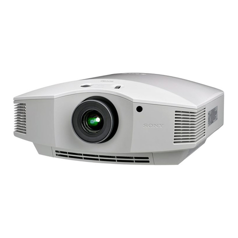
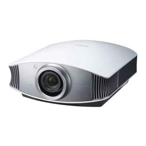
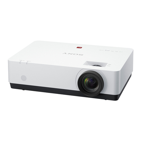
VPL-ES4/EX4
Table of Contents
1. Service Information
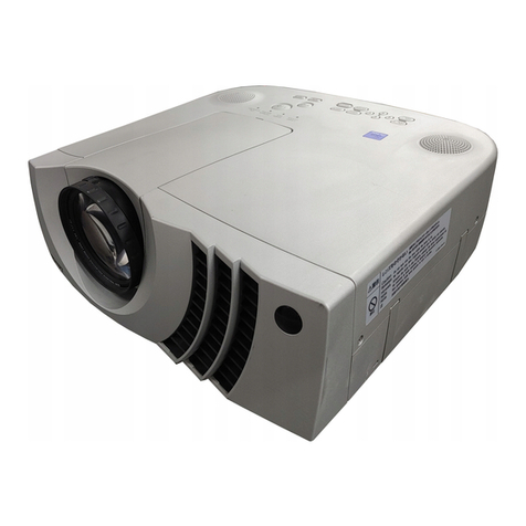
1-1. Appearance Figure ..........................................................1-1
1-2. Board Locations ..............................................................1-1
1-3. Disassembly .................................................................... 1-2
1-3-1. Upper Case Assembly ........................................... 1-2
1-3-2. Front Case Assembly and
Sub Rear Case Assembly ......................................1-2
1-3-3. Main Board ............................................................ 1-3
1-3-4. Tunnel Outlet Section ............................................1-4
1-3-5. Main Board Bracket Section ................................. 1-4
1-3-6. Lamp Power Supply ..............................................1-5
1-3-7. Power Board ..........................................................1-5
1-3-8. Optics Section ....................................................... 1-6
1-3-9. Detection Switch Board ........................................ 1-7
1-3-10. DC Fan .................................................................. 1-7
1-4. Warning on Power Connection ....................................... 1-8
2. Electrical Adjustments
2-1. Initial Values of Adjustment Items ................................. 2-1
2-2. Memory Structure ........................................................... 2-5
3. Troubleshooting
3-1. Electric Troubleshooting ................................................ 3-1
3-2. Power Board Troubleshooting ........................................3-3
3-2-1. No Power ............................................................... 3-3
3-2-2. Failure of Turn on Lamp ....................................... 3-4
4. Spare Parts
4-1. Notes on Repair Parts .....................................................4-1
4-2. Exploded Views .............................................................. 4-2
4-3. Electrical Parts List ......................................................... 4-4
4-4. Packing Materials & Supplied Accessories ....................4-4
5. Block Diagram
Overall ............................................................................ 5-1
6. Diagram
6-1. Frame Schematic Diagram ............................................. 6-1

