manuals.online logo
Brands
  1. Home
  2. •
  3. Brands
  4. •
  5. Sony
  6. •
  7. Receiver
  8. •
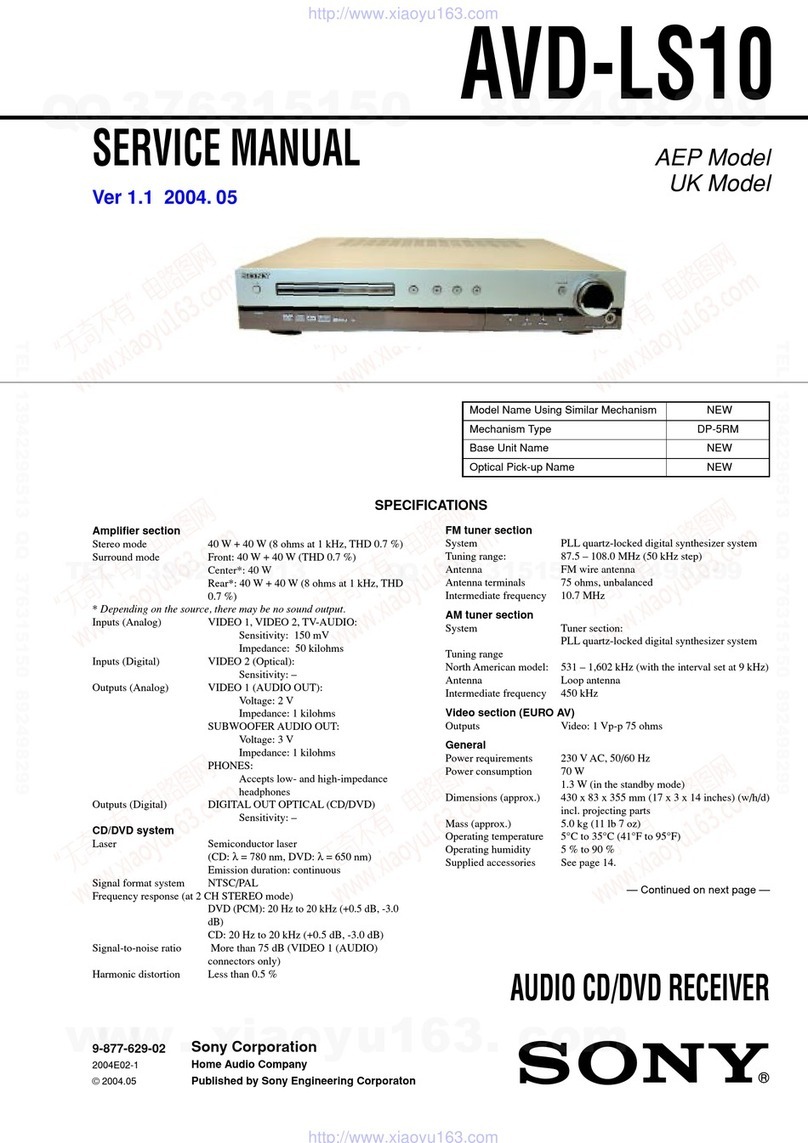
  9. Sony BKM-126M User manual

Sony BKM-126M User manual

Other Sony Receiver manuals

Sony STR-DG810 User manual

Sony

Sony STR-DG810 User manual

Sony STR-AV1020 User manual

Sony

Sony STR-AV1020 User manual

Sony HCD-HDX285 - Dvd Home Theater System User manual

Sony

Sony HCD-HDX285 - Dvd Home Theater System User manual

Sony ICF-403L User manual

Sony

Sony ICF-403L User manual

Sony XLR-1 User manual

Sony

Sony XLR-1 User manual

Sony STR-DN2010 Manual de instrucciones User manual

Sony

Sony STR-DN2010 Manual de instrucciones User manual

Sony HCD-SHAKE10 User manual

Sony

Sony HCD-SHAKE10 User manual

Sony STR-DA2400ES User manual

Sony

Sony STR-DA2400ES User manual

Sony XA-V7W Guide

Sony

Sony XA-V7W Guide

Sony SS-TS500 User manual

Sony

Sony SS-TS500 User manual

Sony DRN-XM01C2 User manual

Sony

Sony DRN-XM01C2 User manual

Sony IAD-IF70 User manual

Sony

Sony IAD-IF70 User manual

Sony HCD-PZ1D User manual

Sony

Sony HCD-PZ1D User manual

Sony MSAC-SR1 User manual

Sony

Sony MSAC-SR1 User manual

Sony STR-DN2010 Manual de instrucciones User manual

Sony

Sony STR-DN2010 Manual de instrucciones User manual

Sony STR-DH100 User manual

Sony

Sony STR-DH100 User manual

Sony BKM-250TG User manual

Sony

Sony BKM-250TG User manual

Sony HCD-DZ3K User manual

Sony

Sony HCD-DZ3K User manual

Sony STR-DA5500ES Installation instructions manual

Sony

Sony STR-DA5500ES Installation instructions manual

Sony STR-K995 User manual

Sony

Sony STR-K995 User manual

Sony HCD-GP8D User manual

Sony

Sony HCD-GP8D User manual

Sony DRC-BT15 User manual

Sony

Sony DRC-BT15 User manual

Sony ICF-PRO70 User manual

Sony

Sony ICF-PRO70 User manual

Sony AVD-S50 User manual

Sony

Sony AVD-S50 User manual

Popular Receiver manuals by other brands

Televes ZAS HD SAT user manual

Televes

Televes ZAS HD SAT user manual

Realistic DX-75 Operating and service instructions

Realistic

Realistic DX-75 Operating and service instructions

Saris 4620 Assembly instructions

Saris

Saris 4620 Assembly instructions

Mini DTR 206C PVR user manual

Mini

Mini DTR 206C PVR user manual

RF Elements TwistPort manual

RF Elements

RF Elements TwistPort manual

Denon DN-200WS user guide

Denon

Denon DN-200WS user guide

Yamaha RX-V467 owner's manual

Yamaha

Yamaha RX-V467 owner's manual

Russound SaphIR 858 instruction manual

Russound

Russound SaphIR 858 instruction manual

Quasonix RDMS Firmware update procedure

Quasonix

Quasonix RDMS Firmware update procedure

Pioneer XV-HTD1 Service manual

Pioneer

Pioneer XV-HTD1 Service manual

ATZ HDMI-V2-44HE150 manual

ATZ

ATZ HDMI-V2-44HE150 manual

Grundig STR 7122 TWIN Service manual

Grundig

Grundig STR 7122 TWIN Service manual

Creative Blaster Modem user guide

Creative

Creative Blaster Modem user guide

Panduit ATLONA AT-OME-RX11 installation guide

Panduit

Panduit ATLONA AT-OME-RX11 installation guide

VOLTCRAFT UTPS-40 operating instructions

VOLTCRAFT

VOLTCRAFT UTPS-40 operating instructions

JVC KW-ADV794 instructions

JVC

JVC KW-ADV794 instructions

Litelink VT-1001 operating instructions

Litelink

Litelink VT-1001 operating instructions

Sangean WR-11 Service manual

Sangean

Sangean WR-11 Service manual

manuals.online logo
manuals.online logoBrands
  • About & Mission
  • Contact us
  • Privacy Policy
  • Terms and Conditions

Copyright 2025 Manuals.Online. All Rights Reserved.

About the OPTION CONFIG menu
When the BKM-126M is installed in the PVM-20L5/14L5
series video minitor, the OPTION CONFIG menu appears.
For details on the OPTION CONFIG menu, refer to the operating
instructions of the monitor in which the adaptor is installed.
BKM–126M
SERIAL 2000
OPT ION CONF IG
Using the Input and Output
Connectors
The configuration of the input and output connectors and the
signals that may be input are shown below.
126M
1
2
IN
OUT
IN
OUT
ANALOG
1
2
3
4
For customers in the USA
This equipment has been tested and found to comply with the
limits for a Class A digital device, pursuant to Part 15 of the
FCC Rules. These limits are designed to provide reasonable
protection against harmful interference when the equipment is
operated in a commercial environment. This equipment
generates, uses, and can radiate radio frequency energy and, if
not installed and used in accordance with the instruction
manual, may cause harmful interference to radio
communications. Operation of this equipment in a residential
area is likely to cause harmful interference in which case the
user will be required to correct the interference at his own
expense.
You are cautioned that any changes or modifications not
expressly approved in this manual could void your authority to
operate this equipment.
The BKM-126M PAL-M Input Adaptor is a video signal input
adaptor for Sony PVM-20L5/14L5 series video monitors.
When installed in an input option slot on the rear panel of the
video monitor, it provides video input and output connectors
for the monitor and a decoder for analog composite PAL-M
signals.
Functions
Decoder for analog composite PAL-M
signals
The BKM-126M is equipped with decoders for analog
composite PAL-M signals.
Analog input and output signal connectors
The BKM-126M is equipped with two input and two output
connectors for analog signals.
Automatic termination (only terminals with
the mark)
The input connectors are terminated at 75 ohms inside, when
no cable is connected to the loop-through output connectors.
When a cable is connected to an output connector, the 75-ohm
termination is automatically released.
Analog composite PAL-M signals
ANALOG INPUT ADAPTOR
BKM-126M
OPERATION GUIDE [English]
1st Edition (Revised 1)
Sony Corporation
B&P Company Printed in Japan
BKM-126M (WW) 2002.6
4-089-635-02 (1) © 2002
Input of analog composite PAL-M signals
You can input analog composite PAL-M signals to connectors
1and 3. When the cable is connected to connectors 2and
4, the 75-ohm termination of connectors 1and 3is
automatically released and you can obtain the loop-through
output from connectors 2and 4. Even if you do not wish to
use loop-through output, you need not attach the 75-ohm
termination to connectors 2and 4.
Specifications
General
Power requirements +5 V, ±6 V
Power consumption 3 W
Operating conditions
Temperature 0°C to 35°C (32°F to 95°F)
Optimum temperature 20°C to 30°C (68°F to 86°F)
Humidity 0% to 90% (no condensation)
Pressure 700 hPa to 1060 hPa
Storage and transport conditions
Temperature –10°C to 40°C (14°F to 104°F)
Humidity 0% to 90% (no condensation)
Pressure 700 hPa to 1060 hPa
Maximum external dimensions
25 ×162 ×122 mm
(1 ×61/2×47/8inches)
(1-slot size)
Mass 270 g (10 oz)
Input/output connectors
Analog composite PAL-M signals
BNC ×2, high impedance, with loop-through output and 75-
ohm automatic termination
Signal characteristics
Analog composite, PAL-M signals
Signal level
Analog composite
1 Vp-p +3 dB/–6 dB
Luminance signal
Frequency characteristics
Analog composite
Monochrome signal:
50 Hz to 6 MHz ±2 dB
Color signal: –30 dB relative to
subcarrier frequency
Chrominance signals
Demodulation axis
R–Y/B–Y
Subcarrier synchronization range
±200 Hz min.
Design and specifications are subject to change without notice.
Installing the Input Adaptor
Note
Disconnect the AC power plug before installing or removing
adaptors.
1Remove the cover of an input option slot on the rear panel
of your video monitor.
2Insert the adaptor.
3Push the adaptor in until it is firmly seated in the
connector inside your video monitor.
4Tighten the both screws to retain the adaptor.
Cover of an input
option slot