Sony HCD-DZ30 User manual

SERVICE MANUAL
Sony Corporation
Audio&Video Business Group
Published by Sony Techno Create Corporation
SPECIFICATIONS
DVD RECEIVER
9-887-992-04
2008H04-1
© 2008.08
AEP Model
UK Model
E Model
Ver. 1.3 2008.08
Model Name Using Similar Mechanism HCD-DZ20
Mechanism Type CDM85-DVBU102
Optical Pick-up Name KHM-313CAA
• HCD-DZ30 is the amplifier, DVD/CD and
tuner section in DAV-DZ30.
This system incorporates with Dolby* Digital and Dolby Pro Logic (II) adaptive
matrix surround decoder and the DTS** Digital Surround System.
* Manufactured under license from Dolby Laboratories.
“Dolby”, “Pro Logic”, and the double-D symbol are trademarks of Dolby
Laboratories.
** Manufactured under license from DTS, Inc.
“DTS” and “DTS Digital Surround” are registered trademarks of DTS, Inc.
Amplifier section
Stereo mode (rated) 50 W + 50 W (at 3 ohms,
1 kHz, 1 % THD)
Surround mode (reference) RMS output power
FL/FR/C/SL/SR*: 67 watts
(per channel at 3 ohms,
1 kHz, 10 % THD)
Subwoofer*: 65 watts (at 3
ohms, 80 Hz, 10 % THD)
* Depending on the sound field settings and the source,
there may be no sound output.
Inputs (Analog)
TV (AUDIO IN) (AEP, UK models)
Sensitivity: 450/250 mV
TV/VIDEO (AUDIO IN) (Except AEP, UK models)
Sensitivity: 450/250 mV
DVD system
Laser Semiconductor laser
(DVD: λ= 650 nm)
(CD: λ= 790 nm)
Emission duration:
continuous
Signal format system
Mexican and Latin American model:
NTSC
Other models: NTSC/PAL
Tuner section
System PLL quartz-locked digital
synthesizer
FM tuner section
Tuning range
North American models: 87.5 – 108.0 MHz
(100 kHz step)
Other models: 87.5 – 108.0 MHz
(50 kHz step)
Antenna (aerial) FM wire antenna (aerial)
Antenna (aerial) terminals 75 ohms, unbalanced
Intermediate frequency 10.7 MHz
AM tuner section
Tuning range
North American, Mexican, and Latin American models:
530 – 1,710 kHz (with the
interval set at 10 kHz)
531 – 1,710 kHz (with the
interval set at 9 kHz)
European, Russian, and Middle Eastern models:
531 – 1,602 kHz (with the
interval set at 9 kHz)
Other models: 531 – 1,602 kHz (with the
interval set at 9 kHz)
530 – 1,610 kHz (with the
interval set at 10 kHz)
Antenna (aerial) AM loop antenna (aerial)
Intermediate frequency 450 kHz
Video section
Outputs
AEP, UK models: VIDEO: 1 Vp-p 75 ohms
R/G/B: 0.7 Vp-p 75 ohms
Except AEP, UK models: VIDEO: 1 Vp-p 75 ohms
S VIDEO:
Y: 1 Vp-p 75 ohms
C: 0.286 Vp-p 75 ohms
COMPONENT:
Y: 1 Vp-p 75 ohms
PB/CB, PR/CR: 0.7 Vp-p
75 ohms
General
Power requirements
Mexican models: 120 VAC, 60 Hz
Venezuelan models: 120 VAC, 60 Hz
Argentine models: 220 – 240 VAC, 50/60 Hz
Latin American models: 110 – 240 VAC, 50/60 Hz
Other models: 220 – 240 VAC, 50/60 Hz
Power consumption On: 80 W
Standby: 0.3 W (at the
Power Saving mode)
Dimensions (approx.) 430 mm × 67 mm ×
310 mm (w/h/d) incl.
projecting parts
Mass (approx.) 3.2 kg
Design and specifications are subject to change
without notice.
HCD-DZ30

HCD-DZ30
2
UNLEADED SOLDER
Boards requiring use of unleaded solder are printed with the lead-
free mark (LF) indicating the solder contains no lead.
(Caution: Some printed circuit boards may not come printed with
the lead free mark due to their particular size)
: LEAD FREE MARK
Unleaded solder has the following characteristics.
• Unleaded solder melts at a temperature about 40 °C higher
than ordinary solder.
Ordinary soldering irons can be used but the iron tip has to be
applied to the solder joint for a slightly longer time.
Soldering irons using a temperature regulator should be set to
about 350 °C.
Caution: The printed pattern (copper foil) may peel away if the
heated tip is applied for too long, so be careful!
• Strong viscosity
Unleaded solder is more viscous (sticky, less prone to flow)
than ordinary solder so use caution not to let solder bridges
occur such as on IC pins, etc.
• Usable with ordinary solder
It is best to use only unleaded solder but unleaded solder may
also be added to ordinary solder.
Notes on chip component replacement
• Never reuse a disconnected chip component.
• Notice that the minus side of a tantalum capacitor may be dam-
aged by heat.
Flexible Circuit Board Repairing
• Keep the temperature of soldering iron around 270 °C during
repairing.
• Do not touch the soldering iron on the same conductor of the
circuit board (within 3 times).
• Be careful not to apply force on the conductor when soldering
or unsoldering.
SAFETY-RELATED COMPONET WARNING!
COMPONENTS IDENTIFIED BY MARK 0OR DOTTED LINE
WITH MARK 0ON THE SCHEMATIC DIAGRAMS AND IN
THE PARTS LIST ARE CRITICAL TO SAFE OPERATION.
REPLACE THESE COMPONENTS WITH SONY PARTS
WHOSE PART NUMBERS APPEAR AS SHOWN IN THIS
MANUAL OR IN SUPPLEMENTS PUBLISHED BY SONY.
Laser component in this product is capable of emitting radiation exceed-
ing the limit for Class 1.
This appliance is classified as a
CLASS 1 LASER product.
This marking is located on the
rear or bottom exterior.
CAUTION
Use of controls or adjustments or performance of procedures other than
those specified herein may result in hazardous radiation exposure.
Special Component Notice
The components identified by mark 9contain confidential infor-
mation.
Strictly follow the instructions whenever the components are re-
paired and/or replaced.
• Abbreviation
E3 : 240V AC area in E model
E12 : 220-240V AC area in E model
E32 : 110-240V AC area in E model
E87 : Venezuelan model
AR : Argentine model
EA : Saudi Arabia model
MX : Mexican model
RU : Russian model
SP : Singapore model
Model Part No.
AEP, UK models 3-280-431-0[]
SP model 3-280-431-1[]
RU model 3-280-431-3[]
E12 model 3-280-431-4[]
E32 model 3-280-431-5[]
AR model 3-280-431-7[]
E3 model 3-280-431-8[]
MX, E87 model 3-280-431-9[]
EA model 4-111-423-0[]
MODEL IDENTIFICATION
– Rear Panel –
Parts No.
Ver. 1.3

HCD-DZ30
3
1. SERVICING NOTES ............................................. 4
2. GENERAL .................................................................. 8
3. DISASSEMBLY
3-1. Case ................................................................................ 12
3-2. Front Panel Assy ............................................................ 12
3-3. FL Board......................................................................... 13
3-4. KEY Board, P-SW Board ............................................... 13
3-5. MAIN Board................................................................... 14
3-6. IO Board (AEP, UK)....................................................... 15
3-7. IO Board (Except AEP, UK)........................................... 15
3-8. DVD Mechanism Deck (CDM85-DVBU102)............... 16
3-9. Tray................................................................................. 16
3-10. Belt, MS-203 Board........................................................ 17
3-11. Optical Pick-up (KHM-313CAA) .................................. 18
4. TEST MODE ............................................................ 19
5. ELECTRICAL ADJUSTMENTS ........................ 23
6. DIAGRAMS
6-1. Block Diagram –RF Section–......................................... 25
6-2. Block Diagram –VIDEO Section– ................................. 26
6-3. Block Diagram –AUDIO Section–................................. 27
TABLE OF CONTENTS
6-4. Block Diagram –AMP Section– ..................................... 28
6-5. Block Diagram –POWER Section–................................ 29
6-6. Printed Wiring Board –MAIN Board (Side A)–............. 31
6-7. Printed Wiring Board –MAIN Board (Side B)–............. 32
6-8. Schematic Diagram –MAIN Board (1/8)–...................... 33
6-9. Schematic Diagram –MAIN Board (2/8)–...................... 34
6-10. Schematic Diagram –MAIN Board (3/8)–...................... 35
6-11. Schematic Diagram –MAIN Board (4/8)–...................... 36
6-12. Schematic Diagram –MAIN Board (5/8)–...................... 37
6-13. Schematic Diagram –MAIN Board (6/8)–...................... 38
6-14. Schematic Diagram –MAIN Board (7/8)–...................... 39
6-15. Schematic Diagram –MAIN Board (8/8)–...................... 40
6-16. Printed Wiring Board –MS-203 Board–......................... 41
6-17. Schematic Diagram –MS-203 Board–............................ 41
6-18. Printed Wiring Board –IO Board–.................................. 42
6-19. Schematic Diagram –IO Board–..................................... 43
6-20. Printed Wiring Boards –KEY, FL, P-SW Board–........... 44
6-21. Schematic Diagram –KEY, FL, P-SW Board–............... 45
7. EXPLODED VIEWS
7-1. Overall Section ............................................................... 56
7-2. Front Panel Assy............................................................. 57
7-3. DVD Mechanism Deck Section (CDM85-DVBU102).. 58
8. ELECTRICAL PARTS LIST .............................. 59

HCD-DZ30
4
SECTION 1
SERVICING NOTES
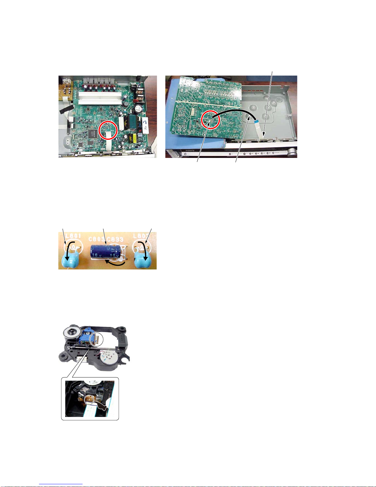
NOTES ON HANDLING THE OPTICAL PICK-UP
BLOCK OR BASE UNIT
The laser diode in the optical pick-up block may suffer electrostat-
ic break-down because of the potential difference generated by the
charged electrostatic load, etc. on clothing and the human body.
During repair, pay attention to electrostatic break-down and also
use the procedure in the printed matter which is included in the
repair parts.
The flexible board is easily damaged and should be handled with
care.
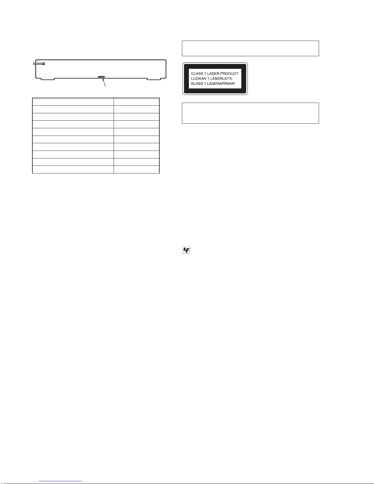
NOTES ON LASER DIODE EMISSION CHECK
The laser beam on this model is concentrated so as to be focused
on the disc reflective surface by the objective lens in the optical
pickup block. Therefore, when checking the laser diode emission,
observe from more than 30 cm away from the objective lens.
DISC TRAY LOCK
The disc tray lock function for the antitheft of an demonstration
disc in the store is equipped.
Setting Procedure :
1. Press the [?/1] button to turn the set on.
2. Press the [FUNCTION] button to set DVD function.
3. Insert a disc.
4. Press the [x] button and the [A] button simultaneously for five
seconds.
5. The message “LOCKED” is displayed and the tray is locked.
Releasing Procedure :
1. Press the [x] button and the [A] button simultaneously for five
seconds again.
2. The message “UNLOCKED” is displayed and the tray is
unlocked.
Note: When “LOCKED” is displayed, the tray lock is not released by
turning power on/off with the [?/1] button.
On cleaning discs, disc/lens cleaners
• Donotuse cleaningdiscsor disc/lenscleaners(including wetor
spray types). These may cause the apparatus to malfunction.
IMPORTANT NOTICE
Caution: This system is capable of holding a still video image or
on-screen display image on your television screen indefinitely.
If you leave the still video image or on-screen display image
displayed on your TV for an extended period of time you risk
permanent damage to your television screen.
Projection televisions are especially susceptible to this.
Attention when transported
Use this mode when returning the set to the customer after repair.
Procedure:
1. Press the [?/1] button to turn the set on.
2. Press the [FUNCTION] button to set the function “DVD”.
3. Remove all discs, and then press two buttons [H] and [?/1]
simultaneously.
4. After a message “MECHA LOCK” is displayed on the
fluorescent indicator tube, pull out the AC plug.
5. To exit from this mode, press the [?/1] button to turn the set
on.
Note about CDs/DVDs
The system can play CD-ROMs/CD-Rs/CD-RWs recorded in the
following formats:
– audio CD format
– VIDEO CD format
– MP3 audio tracks, JPEG image files, and DivX video files*
of format conforming to ISO 9660 Level 1/Level 2, or its
extended format, Joliet
The system can play DVD-ROMs/DVD+RWs/DVD-RWs/
DVD+Rs/DVD-Rs recorded in the following formats:
– MP3 audio tracks, JPEG image files, and DivX video files* of
format conforming to UDF (Universal Disc Format)
* Except for United Kingdom model.
Example of discs that the system cannot play
The system cannot play the following discs:
• CD-ROMs/CD-Rs/CD-RWs other than those recorded in the
formats listed on “Note about CDs/DVDs”
• CD-ROMs recorded in PHOTO CD format
• Data part of CD-Extras
• DVD Audios
• Super Audio CD
• DATA DVDs that do not contain MP3 audio tracks, JPEG
image files, or DivX video files*
* Except for United Kingdom model.
• DVD-RAMs
Also, the system cannot play the following discs:
• A DVD VIDEO with a different region code
• A disc that has a non-standard shape (e.g., card, heart)
• A disc with paper or stickers on it
• Adisc that has the adhesive of cellophane tape or a sticker still
left on it
Notes about CD-R/CD-RW/DVD-R/DVD-RW/DVD+R/
DVD+RW
In some cases, CD-R/CD-RW/DVD-R/DVD-RW/DVD+R/DVD+RW
cannot be played on this system due to the recording quality or
physicalcondition ofthe disc, orthe characteristicsof therecording
device and authoring software.
The disc will not play if it has not been correctly finalized. For
more information, see the operating instructions for the recording
device.
Note that some playback functions may not work with some
DVD+RWs/DVD+Rs, even if they have been correctly finalized.
In this case, view the disc by normal playback. Also some DATA
CDs/DATA DVDs created in Packet Write format cannot be
played.
Copyrights
This product incorporates copyright protection technology that is
protected by U.S. patents and other intellectual property rights.
Use of this copyright protection technology must be authorized by
Macrovision, and is intended for home and other limited viewing
uses only unless otherwise authorized by Macrovision. Reverse
engineering or disassembly is prohibited.
This system incorporates with Dolby* Digital and Dolby Pro Logic
(II) adaptive matrix surround decoder and the DTS** Digital
Surround System.
* Manufactured under license from Dolby Laboratories.
“Dolby”, “ProLogic”,and thedouble-Dsymbol aretrademarks
of Dolby Laboratories.
** Manufactured under license from DTS, Inc.
“DTS” and “DTS Digital Surround” are registered trademarks
of DTS, Inc.
LASER DIODE AND FOCUS SEARCH
1. Open the case and turn POWER on with no disc inserted.
2. Confirm that the following operation is performed while
observing the objecting lens from the clearance of DVD
mechanism deck.
1) Confirm that laser beam is spread.
2) Up and down motion of the objective lens. (2 times)

HCD-DZ30
5
How to open the disc table when power switch turns off
Insert a tapering driver into the aperture of the unit bottom, and slide it in the direction of the arrow.
When the self-diagnosis function is activated to
prevent the system from malfunctioning, a 5-
character service number (e.g., C 13 50) with a
combination of a letter and 4 digits appears on
the TV screen or front panel display. In this case,
check the following table.
When displaying the version
number on the TV screen
When you turn on the system, the version
number [VER.X.XX] (X is a number) may
appear on the TV screen. Although this is not a
malfunction and for Sony service use only,
normal system operation will not be possible.
Turn off the system, and then turn on the system
again to operate.
Self-diagnosis Function
(When letters/numbers appear in the
display)
First 3
characters of
the service
number
Cause and/or corrective action
C 13 The disc is dirty.
Clean the disc with a soft cloth.
C 31 The disc is not inserted correctly.
Restartthesystem, thenre-insert
the disc correctly.
E XX
(xx is a number) To prevent a malfunction, the
system has performed the self-
diagnosis function.
Contact your nearest Sony
dealer or local authorized Sony
service facility and give the 5-
character service number.
Example: E 61 10
C:13:50
VER.X.XX
The lever is moved in the direction of the arrow with the thin rod.
DVD lid

HCD-DZ30
6
Prevention of electric shock and damage to IC
When disassembling the machine, be sure to discharge the charged electricity in the below point.
Use a resistor of 800 ohms, 2 Watts for discharging.
MAIN BOARD (SIDE A)
IC3250 IC3100
IC3300 IC3150
TP3053 800 Ω/2W
TP3054
IC3200
IC3400 Point of discharge for
TP3053 and TP3054
R912 FR901
C903
T901
MAIN BOARD (SIDE B)
800 Ω/2W
Point of discharge for
FR901 and R912

HCD-DZ30
7
MAIN board service position
Please take the above-mentioned position in the repair of MAIN board.
In that case, it is necessary the following extension cable during CN801 on FL board and CN509 on MAIN board.
Note on replacement of C803, L801, and L802
Please fold in the directtion of the arrow and set up at replacement of C803, L801, and L802 on FL board.
L801 L802C803
+
–
Precaution when installing a new OP unit /
Precaution before unsoldering the static electricity prevention solder bridge
When installing a new OP unit, be sure to connect the flexible printed circuit board first of all
before removing the static electricity prevention solder bridge by unsoldering.
Remove the static electricity prevention solder bridge by unsoldering after the flexible printed
circuit board has already been connected.
(Do not remove nor unsolder the solder bridge as long as the OP unit is kept standalone.)
CN509
CN801
extension cable
jig P/N: J-2501-231-A
(pitch 1.00 mm/15p/300L)

HCD-DZ30
8
SECTION 2
GENERAL This section is extracted
from instruction manual.
Front panel
"/(on/standby) (18)
#"(open/close) (18)
$Disc operation (18)
%FUNCTION (18)
&Front panel display (78)
'(remote sensor) (8)
(VOLUME control (18)
)Disc tray (18)
R
AEP, UK MODEL
EXCEPT AEP, UK MODEL
ear panel
"SPEAKER jacks (9)
#EURO AV 5OUTPUT (TO TV) jack (9)
$AM terminal (9)
%COAXIAL FM 75Ωjack (9)
SPEAKER
ANTENNA
FRONT R FRONT L SUR R SUR L CENTER WOOFER
EURO AV
OUTPUT(TO TV)
COAXIAL
AM
FM75
"SPEAKER jacks (9)
#TV/VIDEO (AUDIO IN R/L) jacks (21)
$MONITOR OUT (S VIDEO/VIDEO) jacks
(18)
%AM terminal (9)
&COAXIAL FM 75Ωjack (9)
'COMPONENT VIDEO OUT jacks (18)
SPEAKER
ANTENNA
COMPONENT VIDEO OUT
FRONT R FRONT L SUR R SUR L CENTER WOOFER
TV/VIDEO
MONITOR OUT
COAXIAL
AM
FM75
RLAUDIO IN (DVD ONLY)
YPB/CBPR/CR
VIDEO
(DVD ONLY)
S VIDEO

HCD-DZ30
9
Fr
AEP, UK MODEL
EXCEPT AEP, UK MODEL
ont panel display
About the indications in the front panel display
"Lights up when the time information of
a title or chapter appears in the front
panel display. (DVD only) (34)
#Lights up when an NTSC disc is loaded.
$Lights up when a station is received.
(Radio only) (47)
%Stereo/Monaural effect (Radio only)(48)
&Lights up when the sleep timer is set.
(52)
'Lights up when the movie or music
mode is selected. (21)
(Playing status (DVD function only)
)Current repeat mode (30)
*Lights up when the child lock function
is set to on. (53)
+Indicates the selected [SPEAKER
FORMATION]. (57)
,Current surround format (Except for
JPEG)
-Lights up when the DYNAMIC BASS is
selected. (51)
.Displays system’s status such as
chapter, title, or track number, time
information, radio frequency, playing
status, sound field, etc.
"Lights up when the time information of
a title or chapter appears in the front
panel display. (DVD only) (38)
#Lights up when the color system is set
toNTSC.(Asian,Australian,and Middle
Eastern models only)
$Lights up when a station is received.
(Radio only) (51)
%Stereo/Monaural effect (Radio only)(52)
&Lights up when the sleep timer is set.
(56)
'Lights up when the movie or music
mode is selected. (25)
(Playing status (DVD function only)
)Current repeat mode (34)
*Lights up when the child lock function
is set to on. (57)
+Lights up when the system outputs
progressive signals (DVD function
only). (19)
,Indicates the selected [SPEAKER
FORMATION]. (61)
-Current surround format (Except for
JPEG)
.Lights up when the DYNAMIC BASS is
selected. (55)
/Displays system’s status such as
chapter, title, or track number, time
information, radio frequency, playing
status, sound field, etc.

HCD-DZ30
10
Remote control
ANGLE (36)
AUDIO (31)
CLEAR FG (25, 50, 60)
D.TUNING XG (48)
DISC SKIP* FH
DISPLAY (34, 49)
DVD MENU XI (31, 44, 50)
DVD TOP MENU RG (31)
DYNAMIC BASS XE (51)
ENTER XH (50)
FUNCTION XT (18, 19, 26, 47,
57)
MOVIE/MUSIC RK (21)
MUTING (18)
Numberbuttons**RH (25,48,50,
54)
PICTURE NAVI (26, 50)
PRESET +/– XL FT (48)
SOUND FIELD RI (22)
SUBTITLE XG (37)
SYSTEM MENU XH (16, 19, 50,
52, 83)
THEATRE SYNC X (51)
TUNING +/– RT(47)
TVF (50)
TV CH +/– XB (50)
TV INPUT RL (50)
TV VOL +/– FI (50)
VIDEO FORMAT (15)
VOLUME +/–** (18, 48, 64)
</(on/standby) (13, 16, 18,
26, 48)
TV </(on/standby) FK (50)
$/9/Y/D/ RE (13, 16, 19, 25,
47, 54) REPLAY/
ADVANCE (18)
/FT XL (18)
N/
/
.RT (24)
SLOWRT (24)
)(play)** FB (18, 26, 56)
STEP (24)
Y(stop) XM (18, 26, 54)
9(pause) RB (18)
;(open/close) RM (18)
DISPLAY XK (15, 25, 54, 79)
0RETURN FE (26)
-/-- FG (50)
* The DISC SKIP button is not
available for this model.
**The ), number 5, and
VOLUME + buttons have
tactile dots.Use thetactile dots
as references when operating
the system.
ALPHABETICAL ORDER
A – O P – Z
BUTTON DESCRIPTIONS

HCD-DZ30
11
SECTION 3
DISASSEMBLY
• This set can be disassembled in the order shown below.
3-8. DVD MECHANISM DECK
(Page 16)
3-9. TRAY
(Page 16)
3-1. CASE
(Page 12)
3-2. FRONT PANEL ASSY
(Page 12)
SET
3-3. FL BOARD
(Page 13)
3-4. KEY BOARD,
P-SW BOARD
(Page 13)
3-5. MAIN BOARD
(Page 14)
3-6. IO BOARD
(AEP,UK)
(Page 15)
3-7. IO BOARD
(EXCEPT AEP,UK)
(Page 15)
3-10. BELT,
MS-203 BOARD
(Page 17)
3-11. OPTICAL PICK-UP
(Page 18)

HCD-DZ30
12
Note: Follow the disassembly procedure in the numerical order shown below.
3-1. CASE
3-2. FRONT PANEL ASSY
case
screw
(CASE3 TP2)
screw
(CASE3 TP2)
five screws
(+BVTP 3 ×8)
two claws
The lever is moved in the direction
of the arrow with the thin rod.
loading panel
front panel assy
three screws
(+BV3 (3-CR))
wire (flat type) (15 core)
(CN509)

HCD-DZ30
13
3-3. FL BOARD
3-4. KEY BOARD, P-SW BOARD
shield (front)
FL board
screw
(+BVTP 2.6 (3CR))
three screws
(+BVTP 2.6 (3CR))
two screws
(+BVTP 2.6 (3CR))
clamp
clamp
wire (flat type) (15 core)
(CN801)
CN805
Route the wire (flat type) as shown below.
knob (vol)
nut
R KEY board
button (AIO)
Remove the
soldering.
harness
button (AIO)
P-SW board
four screws
(+BVTP 2.6 (3CR))
screw
(+BVTP 2.6 (3CR))

HCD-DZ30
14
3-5. MAIN BOARD
Attaching the two radiation sheets on the
IC MAIN board first, and then attach the
heatsink (AMP).
two screws
(+BV3 (3-CR))
RE fourteen screws
(+BV3 (3-CR))
heatsink (AMP)
RT three screws
(+BVTP 3 ×8)
RG MAIN board
two radiation sheets
screw (+BVTP 3 ×12)
radiation
sheets
heatsink (AMP)
IC on the
MAIN board
wire (flat type) (15 core)
(CN508) (EXCEPT AEP, UK)
wire (flat type) (17 core)
(CN507) (AEP, UK)
wire (flat type) (13 core)
(CN1301)
wire (flat type) (24 core)
(CN1101)
wire (flat type) (5 core)
(CN1202)
wire (flat type) (15 core)
(CN509)
CN1201 (6P)
RB CN901 (2P)

HCD-DZ30
15
3-6. IO BOARD (AEP, UK)
3-7. IO BOARD (EXCEPT AEP, UK)
IO board
tuner (FM/AM)
wire (flat type) (17 core)
(CN601)
wire (flat type) (13 core)
(CN201)
wire (flat type) (11 core)
(CN101)
two screws
(+BVTT 2.6 ×6)
two screws
(+BVTP 3 ×8)
two screws
(+BVTT 2.6 ×6)
IO board
tuner (FM/AM)
three screws
(+BVTP 3 ×8)
wire (flat type) (15 core)
(CN602)
wire (flat type) (9 core)
(CN102) wire (flat type) (13 core)
(CN201)

HCD-DZ30
16
3-9. TRAY
3-8. DVD MECHANISM DECK (CDM85-DVBU102)
The lever is moved in the direction
of the arrow with the thin rod.
loading panel
DVD mechanism deck
(CDM85-DVBU102)
three screws
(+BV3 (3-CR))
wire (flat type) (24 core)
(CN1101)
wire (flat type) (5 core)
CN1201 (6P)
two claws
tray
Move the chuck cam
in the direction of the arrow.
bottom side

HCD-DZ30
17
3-10. BELT, MS-203 BOARD
two claws
three claws
MS-203 board
DC motor
belt
chuck cam
screw
(M 1.7 ×2.5)

HCD-DZ30
18
3-11. OPTICAL PICK-UP (KHM-313CAA)
two claws
two claws
chuck cam
base unit
FFC holder
two insulator screws
two insulators
two insulators
RB optical pick-up
(KHM-313CAA)
two claws
BU holder

HCD-DZ30
19
SECTION 4
TEST MODE
Note: Incorrect operations may be performed if the test mode is not
entered properly.
In this case, press the [?/1] button to turn the power off, and
retry to enter the test mode.
1. Cold Reset
• The cold reset clears all data including preset data stored in the
RAM to initial conditions. Execute this mode when returning
the set to the customers.
Procedure:
1. Press the [?/1] button to turn the power on.
2. Press three buttons [x], [A] and [?/1] simultaneously.
3. When this button is operated, display as “COLD RESET” for
a while and all of the settings are reset.
2. Panel Test Mode
• This mode is used to check the software version, FL, LED and
KEY.
2-1. Display Test Mode
Procedure:
1. Press the [?/1] button to turn the power on.
2. Press three buttons [X], [.] and [A] simultaneously.
3. When the display test mode is activated, all segments are turned
on.
4. To exit from this mode, press three buttons [X], [.] and [A]
simultaneously.
2-2. Version Test Mode
Procedure:
1. When the display test mode is activated, press the [.] button
and the message “AS1” is displayed, the version test mode is
activated.
2. Whenever the [.] button is pressed, the display changes in
the following order.
“AS1”(Modelname)U“CE2*1”(Destination) UMC
*1: CE2 changes depending on destination.
3. Press the [>] button and the date of the software production
is displayed.
4. Press the [>] button again and the version is displayed.
5. To exit from this mode, press three buttons [X], [.] and [A]
simultaneously.
2-3. Key Test Mode
Procedure:
1. When the display test mode is activated, press the [H] button,
to select the key test mode.
2. To enter the KEY test mode, the fluorescent indicator displays
“K0 V0”. Each time an another button is pressed, “KEY” value
increases. However, once a button is pressed, it is no longer
taken into account. When all keys are pressed correctly, “K8
V0” is displayed.
3. When the [VOLUME] control is turned in the direction of (+),
“V0” is changed to “V1”, then ... “V9”.
When the [VOLUME] control is turned in the direction of (–),
“V0” is changed to “V9”, then ... “V1”.
4. To exit from this mode, press three buttons [X], [.] and [A]
simultaneously.
3. Disc Tray Lock
The disc tray lock function for the antitheft of an demonstration
disc in the store is equipped.
Setting Procedure :
1. Press the [?/1] button to turn the set on.
2. Press the [FUNCTION] button to set DVD function.
3. Insert a disc.
4. Press the [x] button and the [A] button simultaneously for five
seconds.
5. The message “LOCKED” is displayed and the tray is locked.
Releasing Procedure :
1. Press the [x] button and the [A] button simultaneously for five
seconds again.
2. The message “UNLOCKED” is displayed and the tray is
unlocked.
Note: When “LOCKED” is displayed, the tray lock is not released by
turning power on/off with the [?/1] button.
4. DVD Ship Mode
Use this mode when returning the set to the customer after repair.
Procedure:
1. Press the [?/1] button to turn the set on.
2. Press the [FUNCTION] button to set the function “DVD”.
3. Remove all disc, and then press two buttons [H] and [?/1]
simultaneously.
4. After a message “MECHA LOCK” is displayed on the
fluorescent indicator tube, pull out the AC plug.
5. To exit from this mode, press the [?/1] button to turn the set
on.
5. AM Step Change (Except AEP, UK)
• A step of AM channels can be changed over between 9 kHz
and 10 kHz.
Procedure:
1. Press the [?/1] button to turn the set ON.
2. Select the function “TUNER”, and press [FUNCTION] button
to select the BAND “AM”.
3. Press the [?/1] button to turn the set OFF.
4. Press two buttons [>] and [?/1] simultaneously, and the
display of fluorescent indicator tube changes to “AM 9k STEP”
or “AM 10k STEP”, and thus the channel step is changed
over.
6. Product Out
This mode moves the optical pick-up to the position durable to
vibration and clears all data including preset data stored in the
RAM to initial conditions. Use this mode when returning the set to
the customer after repair.
Procedure:
1. Press the [?/1] button to turn the power on.
2. Press the [FUNCTION] button to set the function “DVD”.
3. Remove all disc, and then press three buttons [>], [A] and
[?/1] simultaneously.
4. After the “STANDBY” blinking display finishes, the message
“MECHA LOCK” is displayed on the fluorescent indicator
tube disconnect the AC power plug, then the ship mode is set.

HCD-DZ30
20
7-1. GENERAL DESCRIPTION
The IOP measurement allows you to make diagnosis and
adjustment simply by using the remote commander and monitor
TV. The instructions, diagnosis results, etc. are given on the on-
screen display (OSD).
Be sure to execute the IOP measurement when a BU (Base Unit)
is replaced.
7-2. HOW TO ENTER TEST MODE
While pressing the [x] and [A] buttons simultaneously, turn
[VOLUME] control in the direction of (+) with the DVD player
in power on.
The Test Mode starts, displayed “SERVICE IN” on this model
display then the menu shown below will be displayed on the TV
screen.
The menu above is the Remocon Diagnosis Menu screen which
consists of five main functions. At the bottom of the menu screen,
the model name and IF-con version. To exit from the Test Mode,
press the power button on the remote commander.
7-3. EXECUTING IOP MEASUREMENT
In order to execute IOP measurement, the following standard
procedures must be followed.
(1) In power on, while pressing the [x] and [A] buttons
simultaneously, turn the [VOLUME] control in the direction
of (+).
(2) Select “2. Drive Manual Operation” by pressing the [2] button
on the remote commander. The screen will appear as shown.
(3) Select “3. Manual Adjustment” by pressing the [3] button on
the remote commander. The screen will appear as shown.
(4) Select “6. IOP” by pressing the [6] button on the remote
commander.
(5) Wait until a hexadecimal number appear.
(6) Convert each data from hexadecimal to decimal using
conversion table.
(7) Please find the label on the rear of the BU (Base Unit).
The default IOP value is written in the label.
(8) Subtract between these two values.
(9) If the remainder is smaller than 93 (decimal), then it is OK.
Howeverif thevalueis higherthan 93,thenthe BUis defective
and need to be change.
(10) Press the [RETURN] button on the remote commander to
return back to previous menu.
(11) Press the [0] button on the remote commander to return to Top
Menu.
DVD SECTION
Remocon Diagnosis Menu
0. External Chip Check
1. Servo Parameter Check
2. Drive Manual Operation
3. Emergency History
4. Version Information
Model Name
IF-con : Ver. XX.XX (XXXX)
Syscon : Ver. X.XXX
: AS1_XX
*
1
*1: Changes depending on destination
Remocon Diagnosis Menu
0. External Chip Check
1. Servo Parameter Check
2. Drive Manual Operation
3. Emergency History
4. Version Information
Model Name
IF-con : Ver. XX.XX (XXXX)
Syscon : Ver. X.XXX
: AS1_XX
*
1
*1: Changes depending on destination
Drive Manual Operation
1. Servo Control
2. Track/Layer Jump
3. Manual Adjustment
4. Tray Aging Mode
5. MIRR time adjust
0. Return to Top Menu
Manual Adjust
1. Track Balance Adjust:
2. Track Gain Adjust:
3. Focus Balance Adjust:
4. Focus Gain Adjust:
5. Eq Boost Adjust:
6. Iop:
7. TRV. Level:
8. S curve(FE) Level:
9. RFL(PI) Level:
0. MIRR Time:
0PChange Value
[RETURN] Return to previous menu
Manual Adjust
1. Track Balance Adjust:
2. Track Gain Adjust:
3. Focus Balance Adjust:
4. Focus Gain Adjust:
5. Eq Boost Adjust:
6. Iop. 5B:
7. TRV. Level:
8. S curve(FE) Level:
9. RFL(PI) Level:
0. MIRR Time:
[RETURN] Return to previous menu
0PChange Value
Table of contents
Other Sony Receiver manuals

Sony
Sony DSS SAT-A1 User manual

Sony
Sony STR-KM7600 User manual

Sony
Sony STR-DE485 User manual

Sony
Sony HCD-BX70DBi User manual

Sony
Sony HCD-SC5 User manual

Sony
Sony STR-GX700ES - Fm Stereo Fm-am Receiver User manual

Sony
Sony STR-ZA810ES User manual

Sony
Sony STR-DH830 User manual

Sony
Sony XAV-AX5000 User manual

Sony
Sony WLL-RX50 User manual

Sony
Sony HWS-AV10K User manual

Sony
Sony XAV-AX200 User manual

Sony
Sony STR-DN840 User manual

Sony
Sony STR-DE895 - Fm Stereo/fm-am Receiver User guide

Sony
Sony ICF-M35OV User manual

Sony
Sony ICF-SW1000T User manual

Sony
Sony STR-DG1100 User manual

Sony
Sony PlayStation PULSE 3D User manual

Sony
Sony STR-DE697 User manual

Sony
Sony STR-DG500 - Multi Channel Av Receiver User manual