Sony STR-DA3300ES - Multi Channel Av Receiver User manual

SONY:
3-209-648-11(3)
Multi
Channel
AV
Receiver
Operating Instructions
__
~oded'e~ploi~~~~~~~~~~~~
Owner's Record
The model and serial numbers are located on the rear
of
the unit. Record the
serial number in the space provided below. Refer to them whenever you call
upon your Sony dealer regarding this product.
Model No. Serial No. _
STR-DA3300ES
©2007 Sony Corporation

WARNING
To reduce the risk of fire or electric
shock, do not expose this apparatus to
rain or moisture.
Do not install the appliance in aconfined space, such
as abookcase or built-in cabinet.
To
prevent fire
or
shock hazard, do not place objects
filled with liquids, such as vases, on the apparatus.
Install this system so that the power cord can be
unplugged from the wall socket immediately in the
event
of
trouble.
Batteries orbatteries installed apparatus shall not be
exposed to excessive heat such as sunshine, fire or
the like.
Don't
throwaway battery with
general house waste; dispose
of
it
correctly
as
chemical waste.
WARNING
This equipmenthas been tested and found to comply
with the limits for aClass Bdigital device, pursuant
to Part
15
of
the FCC Rules. These limits are
designed to provide reasonable protection against
harmful interference in aresidential installation.
This equipment generates, uses, and can radiate
radio frequency energy and,
if
not installed and used
in accordance with the instructions, may cause
harmful interference to radio communications.
However, there is no guarantee that interference will
not occur in aparticular installation.
If
this
equipment does cause harmful interference to radio
or television reception, which can be determined by
turning the equipment off and on, the user is
encouraged to try to correct the interference by one
or more
of
the following measures:
-Reorient or relocate the receiving antenna.
-Increase the separation between the equipment
and receiver.
-Connect the equipment into an outlet on acircuit
different from that to which the receiver is
connected.
-Consult the dealer or an experienced
radiorrV
technician for help.
NO USER-SERVICEABLE PARTS INSIDE
REFER SERVICING TO QUALIFIED SERVICE PERSONNEL
CAUTION: TO REDUCE THE RISK OF ELECTRIC SHOCK,
DO NOT REMOVE COVER (OR BACK)
Note
to
CATV
system
installer:
This reminder is provided to call CATV system
installer's attention to Article 820-40
of
the NEC
thatprovides guidelines for propergrounding and, in
particular, specifies that the cable ground shall be
connected to the grounding system
of
the building,
as close to the point
of
cable entry as practical.
CAUTION
You
are cautioned that any changes or modification
not expressly approved in this manual could void
your authority to operate this equipment.
For
customers
in
the
United
States
~
rRISK
OF'
ELECTR:::::-l
l'
in
DO NOT OPEN
~
This symbol is intended to alert the
user to the presence
of
uninsulated
"dangerous voltage" within the
product's enclosure that may be
of
sufficient magnitude to constitute a
risk
of
electric shock to persons.
This symbol is intended to alert the
user to the presence
of
important
operating and maintenance
(servicing) instructions in the
Ii
terature accompanying the
appliance.
2
GB

About
This
Manual
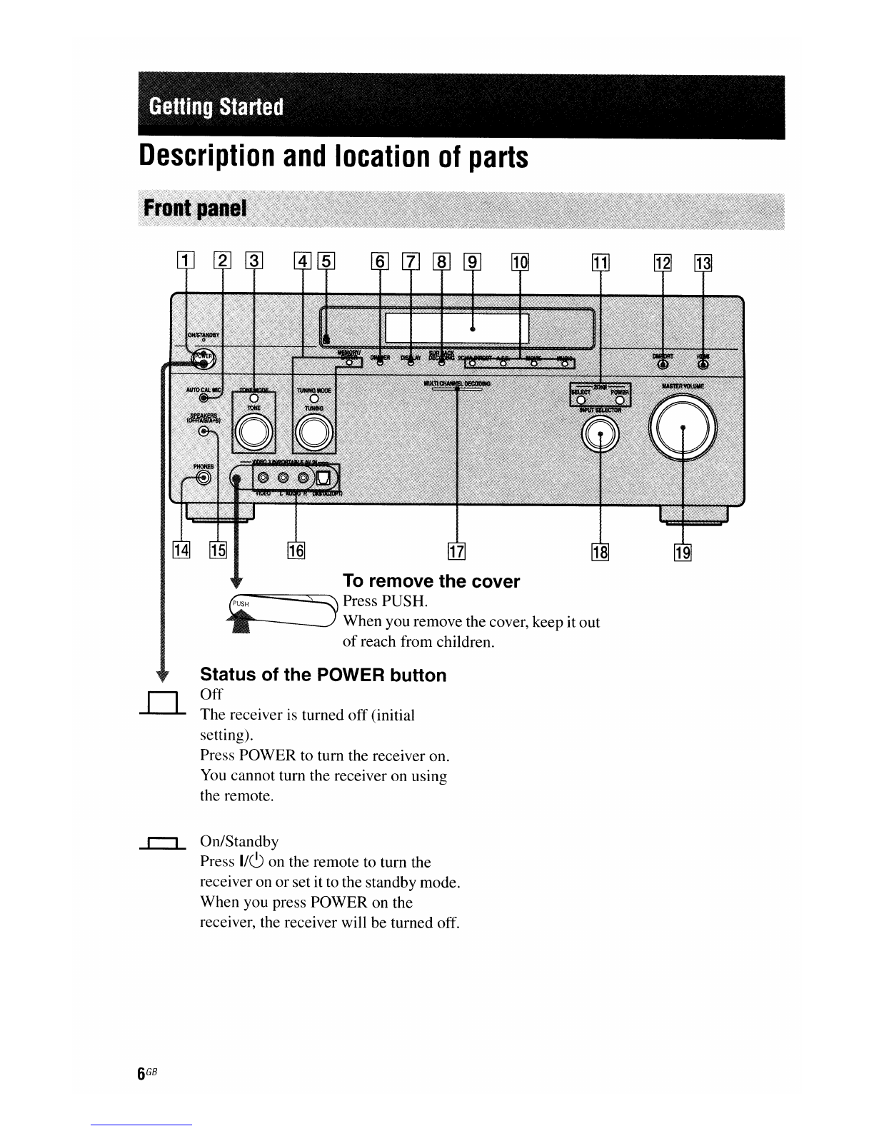
•The instructions in this manual are for model
STR-DA3300ES. Check your model number by
looking at the lower right comer
of
the front panel.
•The instructions in this manual describe the
controls on the supplied remote. You can also use
the controls on the receiver
if
they have the same
or
similar names
as
those on the remote.
•"Neural-THX" and "neural THX" introduced in
the Operating Instructions and displayed in the
display window and onthe GUImenu screen mean
Neural-
THX
Surround.
This receiver incorporates Dolby* Digital and Pro
Logic Surround and the DTS** Digital Surround
System.
*Manufactured under license from Dolby
Laboratories.
Dolby, Pro Logic, Surround EX, and the double-
Dsymbol are trademarks
of
Dolby Laboratories.
**
Manufactured under license from DTS, Inc.
"DTS", "DTS-ES" and "Neo:6" are registered
trademarks
of
DTS, Inc. "DTS 96/24" is a
trademark
of
DTS, Inc.
This receiver incorporates High-Definition
Multimedia Interface
(HDMITM)
technology.
HDMI, the HDMI logo and High-Definition
Multimedia Interface are trademarks or registered
trademarks
of
HDMI Licensing LLC.
The
XM
name and related logos are registered
trademarks
of
XM
Satellite Radio Inc.
©2006 SIRIUS Satellite Radio Inc. "SIRIUS" and
the SIRIUS dog logo are registered trademarks
of
SIRIUS Satellite Radio Inc.
This product using Neural Surround, THX
Technologies is manufactured under license from
Neural Audio Corporation and THX Ltd. Sony
Corporation hereby grants the user anon-exclusive,
non-transferable, limited right to use this product,
and other related technologies dully licensed owned
by Neural Audio Corporation and/or THX Ltd.,
following US and foreign patent and patent pending
laws. Neural Surround is atrademark owned by
Neural Audio Corporation, THX is atrademark
of
THX Ltd., which may be registered in some
jurisdictions.
The font type (Shin Go R) installed in this receiver
is
provided by MORISAWA &COMPANY LTD.
These names are the trademarks
of
MORISAWA &
COMPANY LTD., and the copyright
of
the font also
belongs to MORISAWA &COMPANY LTD.
iPod is atrademark
of
Apple Inc., registered in the
U.S. and other countries.
All other trademarks and registered trademarks are
n!I.
of
their respective holders. In this manual, ™and ®
~
marks are not specified.
Hereby, Sony Corporation declares that this
STR-DA3300ES Multi Channel
AV
Receiver is in
compliance with the essential requirements and
other relevant provisions
of
Directive I999/5/EC.
For details, please access the following URL:
http://www.compliance.sony.de/
The Bluetooth word mark and logos are owned by
the Bluetooth SIG, Inc. and any use
of
such marks
by Sony Corporation is under license.
Other trademarks and trade names are those
of
their
respective owners.
"M
-crew Server" is atrademark
of
Sony
Corporation.
"x.v.Color" is atrademark
of
Sony Corporation.

Table
of
Contents
Getting Started
Description and location
of
parts 6
I:
Installing speakers
15
2:
Connecting speakers
17
3:
Connecting the monitor
19
4a: Connecting the audio components
21
4b: Connecting the video components 26
5:
Connecting the antennas (aerials)
35
6:
Preparing the receiver and the remote 36
7:
Operating the receiver using the GUI
(Graphical User Interface) 38
8:
Setting the speakers
41
9:
Calibrating the appropriate speaker settings
automatically (Auto Calibration) 43
Playback
Selecting acomponent 50
Listening to aSuper Audio CD/CD 52
Watching aDVD/Blu-ray Disc 53
Enjoying video games 54
Watching video
55
Amplifier Operations
Settings for the audio
(Audio settings menu) 56
Settings for the video
(Video settings menu) 57
Settings for HOMI(HDMI menu) 57
Settings for the system
(System settings menu) 58
Enjoying Surround Sound
Enjoying apre-programmed sound field 59
Adjusting the sound effect
63
Using the surround back decoding mode
65
Enjoying the surround effect at low volume
levels (NIGHT MODE) 67
Advanced Speakers Setting
Up
Adjusting the speaker settings manually 68
Adjusting the equalizer 74
Tuner Operations
Listening to FM/AM radio 76
Listening to satellite radio 79
Other Operations
Converting analog video input signals ....... 88
Using the DIGITAL MEDIA PORT
adapter 88
Naming inputs 92
Switching between digital and analog audio
(INPUT MODE) 93
Enjoying the sound/images from other
inputs 94
Changing the display 96
Using the sleep timer 100
Recording using the receiver 100
Listening to the sound in another zone
(ZONE 2operations)
101
Using abi-amplifier connection 105
Using the CONTROL SControl System 106
Operating without connecting
to
the
TV
107
Using the Remote
Operating each component using the
remote 117
Programming the remote 119
Performing several commands in sequence
automatically (Macro Play) 122
Setting remote control codes that are not
stored in the remote 124
Clearing all the contents
of
the remote's
memory 126

Additional Information
Glossary 127
Precautions 129
Troubleshooting 130
Specifications 134
Index 137

lIetlillg
SlalleR
Description
and
location
of
parts
To
remove the cover
~~===:::s=----
Press PUSH.
When you remove the cover, keep it out
of
reach from children.
Status of the POWER button
Off
The receiver
is
turned off (initial
setting).
Press POWER to turn the receiver on.
You
cannot turn the receiver on using
the remote.
On/Standby
Press 1/(9 on the remote to turn the
receiver on or set it to the standby mode.
When you press POWER on the
receiver, the receiver will be turned off.

Name Function Name Function ..
[I] POWER Press to
tum
the
[ill]
2CH/A.DIRECT Press to select sound
receiver on
or
off. A.F.D. field (page 59). G)
(1)
...
[2J
AUTO CAL MIC =
Connects to the MOVIE
~
jack supplied optimizer
(Q
MUSIC
en
microphone for the
...
m
[1]
ZONEI ""'I
Digital Cinema Auto Press SELECT
...
(1)
Calibration function POWER, repeatedly to select
Q.
(page 44). SELECT zone 2
or
main zone.
~TONE
MODE Adjusts FRONT/ Each time you press
TONE CENTER! POWER, the output
SURROUND/ signals for the selected
SURROUND BACK zone will be turned on
BASS and TREBLE. or
off
(page 101).
Press TONE MODE
[2]
DMPORT Press to select the
repeatedly to select audio/video input
BASS
or
TREBLE, signal from the
then turn TONE to component connected
adjust the level. to the DIGITAL
@]
MEMORYI Press to operate atuner MEDIA PORT adapter
ENTER (FM/AM) and satellite (page 22, 88).
~HDMI
TUNING MODE radio (XM/SIRIUS) Press to select input
(page 113-115). source from the
TUNING component connected
rID
Remote sensor Receives signals from to the HDMI IN jack.
remote commander.
[H]
PHONES jack Connects to
rnJ
DIMMER Press repeatedly to headphones.
adjust brightness
of
the
[1§]
SPEAKERS Switch to OFF, A, B,
display. (OFF/AlB/A+B) A+B
of
the front
[l]
DISPLAY Press repeatedly to speakers (page 43).
select information
[§]
VIDEO 3INI Connect to aportable
displayed on the PORTABLEAV audio/videocomponent
display.
IN
jacks such as acamcorder or
[ID
SUR BACK Press to activate SB video game.
DECODING DECODING
[Z]
MULTI Lights up when multi-
(page 65). CHANNEL channel audio signals
[ID
Display The current status
of
DECODING are decoded.
window the selectedcomponent lamp
or alist
of
selectable
items appears here
(page 97).
conNnued---------
7
GB

Name
~INPUT
SELECTOR
~MASTER
VOLUME
Function
Tum to select the input
source to play back.
To
select the input
source for zone
2,
press
ZONE/SELECT ([1])
to select zone 2first
("ZONE 2INPUT"
appears on the display),
then turn INPUT
SELECTOR to select
the input source.
Turn to adjust the
volume level
of
all
speakers at the same
time.

..
C)
CD
...
~
~
cc
en
...
S»
"'"'I
...
CD
C.
[I]
DIGITAL INPUT/OUTPUT section
[2J
ANTENNA section
Connects to a
SiriusConnectHome
tuner (not supplied)
(page 80).
Connects to the XM
Mini Tuner and
Home Dock (not
supplied) (page 80).
Connects to the AM
loop antenna (aerial)
supplied with this
receiver (page 35).
XMjack
AM
ANTENNA
jack
SIRIUS
jack
FMANTENNA Connects to the FM
jack
wire antenna (aerial)
supplied with this
receiver (page 35).
Connect to aDVD
player, Blu-ray Disc
Player,
or
asatellite
tuner. An image and
the sound are output
to TV or aprojector
(page 19, 27).
HDMIIN/
OUT* jacks
OPTICAL IN/
OUTjacks
COAXIAL IN
jacks
D
[Cc==QI
Connect to aDVD
player, Super Audio
__________
CD player, etc. The
COAXIAL jack
provides abetter
quality sound (page
19, 21, 22, 29, 30).
~
RS-232C port
Used for
maintenance and
service.
conHnued----------

rnJ
VIDEO/AUDIO INPUT/OUTPUT
section
@]
DMPORT
(I
I)
Connects to aSony
DIGITAL MEDIA
PO
RT
adapter
(page 22).
AUDIO IN/
OUT
jacks Connect to a
VCR
or
aDVD player etc.
(page
19,29,30,31).
[§J
Control jack for Sony equipment
and other external components VIDEO IN/
OUT* jacks
CTRL SIN/ Connect to Sony
TV,
OUT jacks DVD player or VCR
with CONTROL S
jack (page 106).
[ID
SPEAKERS section
TRIGGER
OUT
jack
Connectsto interlock
on/off
of
the power
supply
of
other 12V
TRIGGER
compliant
components, or the
amplifier/receiver
of
zone 2(page 103).
VIDEO
@
AUDIO
OUT
€)
€)
AUDIO OUT
jacks
VIDEO OUT
jack
Connect to the
component
in
zone 2
(page 101).
Connects to speakers
(page 17).
IR
REM
aTE
Connect an
IR
IN/OUT jacks repeater (page 104).
[§J
COMPONENT VIDEO INPUT/
OUTPUT section
*
You
can watch the selected input image when you
connect the MONITOR VIDEO
OUT
jackto aTV
(page 19).
You
can operate this receiver using a
GUI (Graphical User Interface) (page 38).
@v
@PBlCB
@PR/CR
Y,
PB/C
B,
PRJ
CRIN/OUT*
jacks
Connect to aDVD
player,
TV,
or a
satellite tuner. (page
19,29,30).
[I]
AUDIO INPUT/OUTPUT section
FRONT
@o
@) @)
@)
@)
@)
@)
~"
AUDIO IN/
OUT jacks
MULTI
CHANNEL
INPUT jacks
Connect to atape
deck or
MD
deck, etc
(page 19, 21, 22, 25).
Connect to aSuper
Audio CD player
or
DVD player with an
analog audio
jack
for
7.1
channel or 5.1
channel sound (page
21,24).
~~~~
PRE OUT jacks Connect to an
external power
amplifier.
10
GB

You
canuse the supplied remote RM-AAL011
to operate the receiver and to control the Sony
audio/video components that the remote is
assigned to operate (page 119).
RM-AAL011
Name
W
AV
1/(9
(onl
standby)
[2]
1/(9
(onl
standby)
rnJ
Input
buttons
[1] ZONE 2
[§]
TEST TONE
[§] AMP
[l]
MUSIC
[ID
MOVIE
Function
Press to turn on
or
offthe audio/
video components that the
remote is assigned to operate
(page 119).
If
you press the
1/(9
([2]) at the
same time, it will tum offthe
receiver and other Sony
components (SYSTEM
STANDBY).
Note
The function
of
the
AV
1/(9
switch changes automatically
each
tim~ou
press the input
button
(~).
Press to tum the receiver on or
off.
If
ZONE 2is selected, only the
main receiver is turned on
or
off
with this button.
To
tum off all
components including an
amplifier in zone
2,
press
1/(9
and
AV
1/(9
(W)
at the same
time (SYSTEM STANDBY).
Press one
of
the buttons to
select the component you want
to use. Press apink-labeled
button after pressing SHIFT
(~).
Whenyou press any
of
the
input buttons, the receiver turns
on. The buttons are factory
assigned to control Sony
components (page 50).
You
can
program the remote to control
non-Sony components
following the steps in
"Programming the remote"
(page 119).
Press to enable the zone 2
operation (page 101).
Press to output the test tone
from each speaker.
Press to enable the receiver
operation (page 38).
Press to select sound field
(page 62).
Press to select sound field
(page 62).
..
C)
CD
...
~
:::J
(Q
en
...
Q)
~
...
CD
Co
conunued----------
11
GB

Name Function Name Function
[ill Numeric Press to
ff§]
...
/~a)
Press to operate the DVD
buttons -preset/tune to preset stations. •a) player, Blu-ray Disc Player, CD
-select track numbers
of
the
II
a) player, MD deck, tape deck, or
CD player, DVD player, Blu-
e:::>
a)
b)
component connected to the
ray Disc Player or
MD
deck.
~/~a)
DIGITAL MEDIA PORT
Press 0/
10
to select track adapter etc.
number
10.
CATEGORY Press
to
select the category
-select channel numbers
of
MODE mode for satellite tuner
the VCR or satellite tuner.
-After pressing TV
(~),
(page 115).
press the numeric buttons to TUNING
+/-
Press to select station
select the TV channels. (page 114).
[Q]
ENTER Press to enter the value after
[ZJ
PRESET Press to register FM/
AM/
selecting achannel, disc or +
b)/_
satellite tuner stations
or
to
track using the numeric buttons. select preset stations.
MEMORY Press
to
store astation during TV CH
+/-
Press TV
(~),
then press TV
tuner operation. CH
+/-
to operate the
TV,
[D]
AMP MENU Press
to
display the menu to satellite tuner, VCR, etc.
operate the receiver.
lm
F1/F2 Press TV
(~),
then press
Fl
or
[12]c:B
Press
+/+/+/+
to select the F2 to select acomponent to
menu items. Then press
8:)
to
operate.
enter the selection. •HDD recorder
+1+1+1+
Fl:HDD
~
OPTIONS Press to display and selectitems F2: DVD player, Blu-ray Disc
Player
from option menus for receiver •DVD/VHS combo player
and DVD player, Blu-ray Disc
Fl:
DVD player, Blu-ray Disc
Player. Player
TOOLS Press to display and select items F2: VHS
from the option menus for DVD
MACR01,
Press AMP
([§]),
then press
player
or
Blu-ray Disc Player,
MACR02
MACROI
or
MACR02
to set
etc. up the macro function
[HJ
MENU Press to display the menu to (page 122).
operate the audio/video TV/INPUT Press TVIINPUT and TV
(~)
components. at the same time to select the
SCREEN/ Press SHIFT
(~),
then press input signal (TV input
or
video
DSPL MENU to switch the display input).
CONTROL mode
of
the menu between WIDE Press repeatedly to select the
SCREEN (to display the menu wide picture mode.
on the TV screen) and DSPL (to
RESOLUTION
Press SHIFT
(~)
then press
display the menu in the display
window). RESOLUTION repeatedly to
~
CATEGORY Press to select the category for change the resolution
of
signals
output from the HDMI
OUT
or
+/-
satellite tuner (page 115). COMPONENT VIDEO
MONITOR OUT
jack
(page 88).
12
GB

Name
Function
Name
Function
..
!ml
DVDI Press to display the menus
of
~
CLEAR Press to
TOP MENU, the DVD player on the
TV
-clear amistake when you
C)
MENU screen. Then use
+1+1+1+
and press the incorrect numeric
CD
...
8J
to perform amenu button. =
:::s
operations (page 118). -return to continuous
(C
playback, etc.
of
the satellite
en
NIGHT Press
AMP
([ID), then press
...
tuner or DVD player.
£»
"'"
MODE NIGHT MODE to activate the
...
CD
NIGHT MODE function >10 Press to select
Co
(page 67). -track numbers over 10
of
the
INPUT Press
AMP
([ID), then press VCR, satellite tuner, CD
player
or
MD deck.
MODE INPUT MODE to select the -channel numbers
of
the
input mode when the same Digital CATV terminal.
components are connected to
both digital and analog jacks D.TUNING Press to enter direct tuning
(page 93). mode (page
77,82).
[gQ]
MUTING Press to turn offthe sound
[2§J
2CHI
Press to select sound field
temporarily. Press the button A.DIRECT (page 59)
or
to switch the audio
again to restore the sound.
of
the selected input to analog
[gj]
MASTER Press to adjust the volume level signal without any adjustment
VOL
+1-
of
all speakers at the same time. (page 113).
l21l
A.F.D. Press to select sound field
TV VOL
+1-
Press
TV
(00),
then press TV
VOL
+1-
to adjust the volume (page 60).
level
of
the
TV.
~
SHIFT Press to light up the button.
It
[221
DISC SKIP Press to skip adisc when using changes the remote button
function to activate the buttons
amulti-disc changer. with pink printing.
~
RETURNI Press to return to the previous
~
SLEEP Press to activate the sleep timer
EXIT 0-' menu
or
exit the menu while the
menu
or
on-screen guide
of
the function and the duration which
the receiver turns off
VCR, DVD player, or satellite automatically (page 100).
tuner is displayed on the TV
screen.
00
TV Press to enable the TV
~
DISPLAY Press to select information operation.
displayed in the display
@j]
RM
SET UP Press to set up the remote.
window, TV screen
of
the VCR, a)See the table on page 118 for information on the
satellite tuner, CD player, DVD
player, BIu-ray Disc Player, or buttons that you can use to control each
MD deck. component.
Note
b)The tactile dot is attached to these buttons ([:::>,
In the SCREENmode, press the PRESET+). Use as amark
of
operation.
button to display the menu on
the
TV
screen.
Notes
•Some functions explained in this section may not
work depending on the model.
•The above explanation is intended to serve as an
example only. Therefore, depending on the
component, the above operation may not be
possible
or
may operate differently than described.
conunued----------
13
GB

RM-AAU018
This remote can only be used to operate the
receiver. You can control the main functions
of
the receiver with simple operations using this
remote.
Name
[1]8:)
+1+1+1.
Function
After
pressin~CREEN/DSPL
CONTROL
(@J),
press
+/+/+/
•to select the menu items.
Then press 8to enter the
selection.
~
Starts play.
~
/~
Skips tracks.
•Stops play.
Press to return to the previous
menu
or
exit the menu.
Press to turn off the sound
temporarily. Press the button
again to restore the sound.
Press to display the menu to
operate the receiver.
Press to operate component
connected to the DIGITAL
MEDIA PORT adapter
(page 88).
Press to display and select items
from option menus.
rID
INPUT Press to select the input source
SELECTOR to play back.
ffQ]
MUTING
ffi] OPTIONS
[ID
MASTER Press to adjust the volume level.
VOLUME +1-
ITIJ
RETURNI
EXIT
[1] DMPORT
[§]MENU
Name
rn
IIC)
(onl
standby)
Function
Press to turn areceiver on oroff.
[12J
DISPLAY Press to select information
displayed in the display
window.
Note
In the SCREEN mode, press the
button to display the menu on
the TV screen.
[2]
2CHI
A.DIRECT
A.F.D.
MOVIE
Press to select sound field
(page 59).
~
SLEEP Press to activate the sleep timer
function and the duration which
the receiver turns
off
automatically (page 100).
MUSIC
~
SCREENI
DSPL
CONTROL
Press to switch the display
mode
of
the menu between
SCREEN (to display the menu
on the
TV
screen) and DSPL (to
display the menu in the display
window).
14
GB

1:
Installing
speakers
..
This receiver allows you to use a7.1 channel
system
(7
speakers and one sub woofer).
To
fully enjoy theater-like multi-channel
surround sound requires five speakers (two
front speakers, acenter speaker, and two
surround speakers) and asub woofer (5.1
channel system).
Example of a
5.1
channel
speaker system configuration
mFront left speaker
IS)Front right speaker
[!1Center speaker
Ii]Surround left speaker
Ii
Surround right speaker
IDSub woofer
You
can enjoy high fidelity reproduction
of
DVD software recorded sound in the Surround
EX format
if
you connect one additional
surround back speaker (6.1 channel system) or
two surround back speakers (7.1 channel
system.) See "Using the surround back
decoding mode" (page 65).
Example of a
7.1
channel
speaker system configuration
mFront left speaker
IS)Front right speaker
[!1Center speaker
Ii]Surround left speaker
Ii
Surround right speaker
(I
Surround back left speaker
mSurround
back right speaker
IDSub woofer
continued-----
15
GB

Tips
•
The
angle 0should be the same.
...
~.
•
When
you connect a6.1 channel speaker system,
place the surround
back
speaker behind the seating
position.
•Since the sub
woofer
does not
emit
highly
directional signals, you can place it wherever you
want.
16
GB

2:
Connecting
speakers
•
Before connecting cords, make sure to
disconnect the AC power cord (mains lead).
"Monaural
audio cord (not supplied)
oSpeaker cords (not supplied)
mCenter
speaker
mFront
speaker
[A]
(L)
[!)Front
speaker
[A]
(R)
DlSurround speaker (L)
II
Surround speaker (R)
II
Surround back speaker (L)b)
[!I
Surround back speaker (R)b)
IDSub
wooferc)
a)
If
you have an additional front speaker
system, connect them to the FRONT
SPEAKERS
~
terminals.
You
can select
the front speaker system you want to use
with the SPEAKERS switch (OFF/AIB/
A+B) on the front panel (page 43).
connnued---
.........
17
GB

b)
If you connect only one surround back
speaker, connect it to the
SUR
BACK
SPEAKERS Lterminals.
c) When you connect asub wooferwith an auto
standby function,
tum
offthe function when
watching movies.
If
the auto standby
function is set to on, it turns to standby mode
automatically based
on
the level
of
the input
signal to asub woofer, then sound may not
be output.
Notes
•When you connect all the speakers with anominal
impedance
of
8ohms
or
higher, set "Impedance" in
the Speaker settings menu to
"8
n." In other
connections, set it to "4 n." For details, see "8:
Setting the speakers" (page 41).
•Before connecting the AC power cord (mains
lead), make sure that metallic wires
of
the speaker
cords are not touching each other between the
SPEAKERS terminals.
Tip
To
connect certain speakers to another power
amplifier, use the PRE
OUT
jacks.
The
same signal
is output from both the
SPEAKERS
terminals and
the PRE
OUT
jacks. For example,
if
you want to
connect
just
the front speakers to another amplifier,
connect that amplifier to the PRE
OUT
FRONT L
and Rjacks.
You can assign the
SUR
BACK SPEAKERS
terminals IIand mto the speakers
of
the
zone
2.
Set
"Sur
BackAssign" to
"ZONE
2" in
the Speaker settings menu.
See "Listening to the sound in another zone
(ZONE 2operations)" (page 101) for details
on connection and operation in zone 2.
18
GB

3:
Connecting
the
monitor
You can watch the selected input image when
you connectthe MONITORVIDEO
OUT
jack
to a
TV.
You can operate this receiver using a
GUI (Graphical User Interface).
TV monitor
It is not necessary to connect all the cables.
Connect audio and video cords according to
the jacks
of
your components.
..
C)
CD
~
:::s
cc
en
...
m
~
...
CD
Q.
Audio signals Video signals
oOptical digital cord (not supplied)
GAudio
cord (not supplied)
eVideo cord (not supplied)
0HDMI
cable (not supplied)
GComponent video cord (not supplied)
continued-----
19
GB

Notes
•Before connecting cords, make sure to disconnect
the AC
power
cord (mains lead).
•
Connect
image display
components
such as a
TV
monitor
or
aprojector to the
MONITOR
VIDEO
OUT
jack
on the receiver. You may not be able to
record, even
if
you connect recording components.
•Turn on the receiver when the video and audio
of
a
playback
component
are being output to a
TV
via
the receiver.
If
the
power
supply
of
the receiver is
not turned on, neither video nor audio is
transmitted.
•Depending on the status
of
the connection
between
the
TV
and the antenna (aerial), the
image
on the
TV
screen may be distorted. In this case, place the
antenna (aerial) farther away from the receiver.
Tips
•
The
receiver has avideo conversion function.
For
details, see
"Notes
on converting video signals"
(page 33).
•
The
sound
of
the
TV
is output from the speakers
connected to the receiver
if
you
connect
the sound
output
jack
of
the
TV
and the
TV
IN
jacks
of
the
receiver. In this configuration, set the sound output
jack
of
the
TV
to
"Fixed"
if
it can
be
switched
between either
"Fixed"
or
"Variable."
•
The
screen saver is activated when the
GUI
menu
is displayed on the
TV
screen and there has been
no
operation attempted for
15
minutes.
20
GB
Other manuals for STR-DA3300ES - Multi Channel Av Receiver
9
Table of contents
Other Sony Receiver manuals

Sony
Sony STR-K1600 User manual

Sony
Sony STR-DA5800ES User manual

Sony
Sony STR-DE697 User manual

Sony
Sony S-AIR AIR-A10R User manual

Sony
Sony STR-AV320 User manual

Sony
Sony STR-KS1100 User manual

Sony
Sony STR-DH130 User manual

Sony
Sony SAT-B2/2 User manual

Sony
Sony HWSBTA2W - Bluetooth Wireless Audio... User manual

Sony
Sony ICF-SW35 User manual