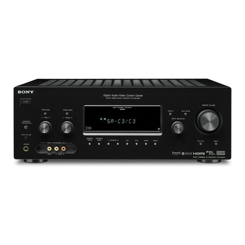
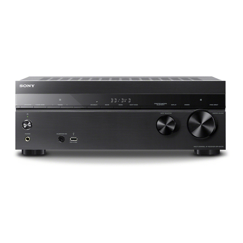
Sony STR-DN1000 User manual

SERVICE MANUAL
Sony Corporation
Audio&Video Business Group
Published by Sony Techno Create Corporation
STR-DN1000
SPECIFICATIONS
MULTI CHANNEL AV RECEIVER
9-889-530-01
2009F05-1
© 2009.06
US Model
Canadian Model
AEP Model
UK Model
E Model
Australian Model
Ver. 1.0 2009.06
This receiver incorporates Dolby* Digital and ProLogic Sur-
round and the DTS** Digital SurroundSystem.
* Manufactured under license from Dolby Laboratories.
Dolby and the double-D symbol are trademarks of Dolby
Laboratories.
** Manufactured under license under U.S. Patent #’s:
5,451,942; 5,956,674; 5,974,380; 5,978,762; 6,226,616;
6,487,535; 7,212,872; 7,333,929; 7,392,195; 7,272,567
& other U.S. and worldwide patents issued & pending.
DTS is a registered trademark and the DTS logos, Symbol,
DTS-HD and DTS-HD Master Audio are trademarks of
DTS, Inc. © 1996-2008 DTS, Inc. All Rights Reserved.
This receiver incorporates High-Definition Multimedia In-
terface (HDMITM) technology. HDMI, the HDMI logo and
High-Definition Multimedia Interface are trademarks or regis-
tered trademarks of HDMI Licensing LLC.
SIRIUS, XM and all related marks and logos are trademarks of
Sirius XM Radio Inc. and its subsidiaries. All rights reserved.
The font type (Shin Go R) installed in this receiver is pro-
vided by MORISAWA & COMPANY LTD. These names are
the trademarks of MORISAWA & COMPANY LTD., and the
copyright of the font also belongs to MORISAWA & COM-
PANY LTD.
This product using Neural-THX® Surround is manufactured
under license from Neural Audio Corporation and THX Ltd.
Sony Corporation hereby grants the user a non-exclusive, non-
transferable, limited right of use to this product under USA
and foreign patent, patent pending and other technology or
trademarks owned by Neural Audio Corporation and THX Ltd.
“Neural Surround”, “Neural Audio”, “Neural” and “NRL” are
trademarks and logos owned by Neural Audio Corporation,
THX is a trademark of THX Ltd., which may be registered in
some jurisdictions. All rights reserved.
iPod is a trademark of Apple Inc., registered in the U.S. and
other countries.
All other trademarks and registered trademarks are of their
respective holders. In this manual, ™ and ® marks are not
specified.
The Bluetooth word mark and logos are owned by the Blue-
tooth SIG, Inc. and any use of such marks by Sony Corporation
is under license.
Other trademarks and trade names are those of their respec-
tive owners.
“M-crew Server” is a trademark of Sony Corporation.
“x.v.Color” and “x.v.Color” logo are trademarks of Sony Cor-
poration.
“BRAVIA” is a trademark of Sony Corporation.
“S-AIR” and its logo are trademarks of Sony Corporation.
DLNA and DLNA CERTIFIED are trademarks and/or service
marks of the Digital Living Network Alliance.
AUDIO POWER
SPECIFICATIONS
POWER OUTPUT AND TOTAL
HARMONIC DISTORTION:
(Models of area code U only)
With 8 ohm loads, both channels driven, from
20 – 20,000 Hz; rated 100 watts per channel
minimum RMS power, with no more than
0.09% total harmonic distortion from 250
milliwatts to rated output.
Amplifier section
Models of area code U, CA1)
Minimum RMS Output Power
(8 ohms, 20 Hz – 20 kHz, THD 0.09%)
100 W + 100 W
Stereo Mode Output Power
(8 ohms, 1 kHz, THD 1%)
110 W + 110 W
Surround Mode Output Power2)
(8 ohms, 1 kHz, THD 10%)
150 W per channel
Amplifier section
Models of area code CEL, CEK, AU, E511)
Minimum RMS Output Power
(8 ohms, 20 Hz – 20 kHz, THD 0.09%)
85 W + 85 W
Stereo Mode Output Power
(8 ohms, 1 kHz, THD 1%)
100 W + 100 W
Surround Mode Output Power2)
(8 ohms, 1 kHz, THD 10%)
140 W per channel
1)Measured under the following conditions:
2)Reference power output for front, center, surround
and surround back speakers. Depending on the
sound field settings and the source, there may be
no sound output.
Frequency response
Analog 10 Hz – 70 kHz,
+0.5/–2 dB (with sound
field and equalizer
bypassed)
Area code Power requirements
U, CA 120 V AC, 60 Hz
CEL, CEK, AU 230 V AC, 50 Hz
E51 240 V AC, 50 Hz
Input
Analog Sensitivity: 500 mV/
50 kohms
S/N3): 96 dB
(A, 500 mV4))
Digital (Coaxial) Impedance: 75 ohms
S/N: 100 dB
(A, 20 kHz LPF)
Digital (Optical) S/N: 100 dB
(A, 20 kHz LPF)
Output (Analog)
AUDIO OUT Voltage: 500 mV/10 kohms
SUBWOOFER Voltage: 2 V/1 kohm
Equalizer
Gain levels ±10 dB, 1 dB step
3)INPUT SHORT (with sound field and equalizer
bypassed).
4)Weighted network, input level.
– Continued on next page –
w
w
w
.
x
i
a
o
y
u
1
6
3
.
c
o
m
Q
Q
3
7
6
3
1
5
1
5
0
9
9
2
8
9
4
2
9
8
T
E
L
1
3
9
4
2
2
9
6
5
1
3
9
9
2
8
9
4
2
9
8
0
5
1
5
1
3
6
7
3
Q
Q
TEL 13942296513 QQ 376315150 892498299
http://www.xiaoyu163.com
STR-DN1000
2
NOTES ON CHIP COMPONENT REPLACEMENT
• Never reuse a disconnected chip component.
• Notice that the minus side of a tantalum capacitor may be dam-
aged by heat.
SAFETY CHECK-OUT
After correcting the original service problem, perform the follow-
ing safety check before releasing the set to the customer:
Check the antenna terminals, metal trim, “metallized” knobs,
screws, and all other exposed metal parts for AC leakage.
Check leakage as described below.
LEAKAGE TEST
The AC leakage from any exposed metal part to earth ground and
from all exposed metal parts to any exposed metal part having a
return to chassis, must not exceed 0.5 mA (500 microamperes.).
Leakage current can be measured by any one of three methods.
1. A commercial leakage tester, such as the Simpson 229 or RCA
WT-540A. Follow the manufacturers’ instructions to use these
instruments.
2. A battery-operated AC milliammeter. The Data Precision 245
digital multimeter is suitable for this job.
3. Measuring the voltage drop across a resistor by means of a
VOM or battery-operated AC voltmeter. The “limit” indication
is 0.75 V, so analog meters must have an accurate low-voltage
scale. The Simpson 250 and Sanwa SH-63Trd are examples
of a passive VOM that is suitable. Nearly all battery operated
digital multimeters that have a 2 V AC range are suitable. (See
Fig. A)
1.5 kΩ0.15 μF
AC
voltmeter
(0.75 V)
To Exposed Metal
Parts on Set
Earth Ground
Fig. A. Using an AC voltmeter to check AC leakage.
SAFETY-RELATED COMPONENT WARNING!
COMPONENTS IDENTIFIED BY MARK 0OR DOTTED LINE
WITH MARK 0ON THE SCHEMATIC DIAGRAMS AND IN
THE PARTS LIST ARE CRITICAL TO SAFE OPERATION.
REPLACE THESE COMPONENTS WITH SONY PARTS
WHOSE PART NUMBERS APPEAR AS SHOWN IN THIS
MANUAL OR IN SUPPLEMENTS PUBLISHED BY SONY.
ATTENTION AU COMPOSANT AYANT RAPPORT
À LA SÉCURITÉ!
LES COMPOSANTS IDENTIFIÉS PAR UNE MARQUE 0SUR
LES DIAGRAMMES SCHÉMATIQUES ET LA LISTE DES
PIÈCES SONT CRITIQUES POUR LA SÉCURITÉ DE FONC-
TIONNEMENT. NE REMPLACER CES COMPOSANTS QUE
PAR DES PIÈCES SONY DONT LES NUMÉROS SONT DON-
NÉS DANS CE MANUEL OU DANS LES SUPPLÉMENTS
PUBLIÉS PAR SONY.
About area codes
The area code of the receiver you purchased is
shown on the lower right portion of the rear panel
(see the illustration below).
Any differences in operation, according to the area
code, are clearly indicated in the text, for example,
“Models of area code AA only”.
LR
OUT
FRONT A
LR
SURROUND
Area code
FM tuner section
T
uning range 87.5 MHz – 108.0 MHz
A
ntenna (aerial) FM wire antenna (aerial)
A
ntenna (aerial) terminals
75 ohms, unbalanced
I
ntermediate frequency
10.7 MHz
V
ideo section
I
nputs/Outputs
Video: 1 Vp-p, 75 ohms
COMPONENT VIDEO:
Y: 1 Vp-p, 75 ohms
PB/CB: 0.7 Vp-p, 75 ohms
PR/CR: 0.7 Vp-p, 75 ohms
80 MHz HD Pass Through
A
M tuner section
T
uning range
A
ntenna (aerial) Loop antenna (aerial)
I
ntermediate frequency
450 kHz
Area code Tuning scale
530 kHz –
10 kHz step 9 kHz step
CEL, CEK – 531 kHz –
1,602 kHz
U, CA, AU, E51
1,710 kHz
531 kHz –
1,710 kHz
General
Power requirements
Power output (DIGITAL MEDIA PORT)
DC OUT: 5V, 0.7 A MAX
Power consumption
Area code Power requirements
U, CA 120 V AC, 60 Hz
Area code Power consumption
U, CA, CEL, CEK,
AU, E51
250 W
CEL, CEK 230 V AC, 50/60 Hz
AU 230 V AC, 50 Hz
E51 120/220/240 V AC,
50/60 Hz
Power consumption (during standby mode)
0.9 W (When “Ctrl for
HDMI” and “S-AIR Stby”
is set to “OFF”)
Dimensions (width/height/depth) (Approx.)
17 × 6 1/4 × 12 7/8 inches
(430 × 157.5 × 324.5 mm)
including projecting parts
and controls
Mass (Approx.) 18 lb 16 oz (8.6 kg)
Supplied accessories
Operating instructions
Quick Setup Guide (1)
GUI Menu List (1)
FM wire antenna (aerial) (1)
AM loop antenna (aerial) (1)
RM-AAP040 Remote commander (1) (US, Canadian)
R6 (size-AA) batteries (2)
Optimizer microphone (ECM-AC2) (1)
Design and specifications are subject to
change without notice.
RM-AAP042 Remote commander (1) (Except US, Canadian)
w
w
w
.
x
i
a
o
y
u
1
6
3
.
c
o
m
Q
Q
3
7
6
3
1
5
1
5
0
9
9
2
8
9
4
2
9
8
T
E
L
1
3
9
4
2
2
9
6
5
1
3
9
9
2
8
9
4
2
9
8
0
5
1
5
1
3
6
7
3
Q
Q
TEL 13942296513 QQ 376315150 892498299
http://www.xiaoyu163.com
STR-DN1000
3
1. SERVICING NOTES ............................................. 4
2. DISASSEMBLY
2-1. Disassembly Flow........................................................... 5
2-2. Case................................................................................. 6
2-3. Front Panel Block ........................................................... 6
2-4. Tuner (FM/AM) .............................................................. 7
2-5. S-AIR Board ................................................................... 7
2-6. DIGITAL VIDEO Board................................................. 8
2-7. STANDBY DCDC Board, AC SELECT Board
(E51 Model).................................................................... 8
2-8. Back Panel ...................................................................... 9
2-9. DSP Board, DIGITAL Board, VIDEO Board................. 9
2-10. CONNECTION Board, Main Block............................... 10
2-11. MAIN Board ................................................................... 10
3. TEST MODE ............................................................ 11
4. ELECTRICAL CHECK ......................................... 16
5. DIAGRAMS
5-1. Block Diagram - MAIN Section -................................... 17
5-2. Block Diagram - HDMI Section -................................... 18
5-3. Block Diagram - VIDEO Section -................................. 19
5-4. Block Diagram - DSP, S-AIR, SIRIUS Section - ........... 20
5-5. Block Diagram - AUDIO Section -................................. 21
5-6. Block Diagram
- PANEL, POWER SUPPLY Section -........................... 22
5-7. Printed Wiring Board
- DIGITAL Board (Component Side) -........................... 24
5-8. Printed Wiring Board
- DIGITAL Board (Conductor Side) -............................. 25
5-9. Schematic Diagram - DIGITAL Board (1/4) -................ 26
5-10. Schematic Diagram - DIGITAL Board (2/4) -................ 27
5-11. Schematic Diagram - DIGITAL Board (3/4) -................ 28
5-12. Schematic Diagram - DIGITAL Board (4/4) -................ 29
5-13. Printed Wiring Board - MAIN Board -........................... 30
5-14. Schematic Diagram - MAIN Board (1/3) -..................... 31
5-15. Schematic Diagram - MAIN Board (2/3) -..................... 32
5-16. Schematic Diagram - MAIN Board (3/3) -..................... 33
5-17. Printed Wiring Board
- DIGITAL VIDEO Board (Side A) - ............................. 34
TABLE OF CONTENTS
5-18. Printed Wiring Board
- DIGITAL VIDEO Board (Side B) - ............................. 35
5-19. Schematic Diagram
- DIGITAL VIDEO Board (1/4) - ................................... 36
5-20. Schematic Diagram
- DIGITAL VIDEO Board (2/4) - ................................... 37
5-21. Schematic Diagram
- DIGITAL VIDEO Board (3/4) - ................................... 38
5-22. Schematic Diagram
- DIGITAL VIDEO Board (4/4) - ................................... 39
5-23. Printed Wiring Board - DSP Board - .............................. 40
5-24. Schematic Diagram - DSP Board - ................................. 41
5-25. Printed Wiring Board - S-AIR Board - ........................... 42
5-26. Schematic Diagram - S-AIR Board -.............................. 42
5-27. Printed Wiring Board - VIDEO Board - ......................... 42
5-28. Schematic Diagram - VIDEO Board -............................ 43
5-29. Printed Wiring Boards
- THERMAL SENSOR Section - ................................... 44
5-30. Schematic Diagram
- THERMAL SENSOR Section - ................................... 44
5-31. Printed Wiring Board - CONNECTION Board -............ 44
5-32. Schematic Diagram - CONNECTION Board - .............. 45
5-33. Printed Wiring Boards - PANEL Section - ..................... 46
5-34. Schematic Diagram - PANEL Section -.......................... 47
5-35. Printed Wiring Boards - POWER SUPPLY Section - .... 48
5-36. Schematic Diagram - POWER SUPPLY Section -......... 49
6. EXPLODED VIEWS
6-1. Case Section.................................................................... 77
6-2. Front Panel Section......................................................... 78
6-3. DIGITAL VIDEO Board Section.................................... 79
6-4. DIGITAL Board Section................................................. 80
6-5. Heatsink Section ............................................................. 81
7. ELECTRICAL PARTS LIST .............................. 82
Accessories are given in the last of the electrical parts list.
• Abbreviation
E51 : Chilean and Peruvian models
w
w
w
.
x
i
a
o
y
u
1
6
3
.
c
o
m
Q
Q
3
7
6
3
1
5
1
5
0
9
9
2
8
9
4
2
9
8
T
E
L
1
3
9
4
2
2
9
6
5
1
3
9
9
2
8
9
4
2
9
8
0
5
1
5
1
3
6
7
3
Q
Q
TEL 13942296513 QQ 376315150 892498299
http://www.xiaoyu163.com
STR-DN1000
4
SECTION 1
SERVICING NOTES
UNLEADED SOLDER
Boards requiring use of unleaded solder are printed with the lead-
free mark (LF) indicating the solder contains no lead.
(Caution: Some printed circuit boards may not come printed with
the lead free mark due to their particular size)
: LEAD FREE MARK
Unleaded solder has the following characteristics.
• Unleaded solder melts at a temperature about 40 °C higher
than ordinary solder.
Ordinary soldering irons can be used but the iron tip has to be
applied to the solder joint for a slightly longer time.
Soldering irons using a temperature regulator should be set to
about 350 °C.
Caution: The printed pattern (copper foil) may peel away if
the heated tip is applied for too long, so be careful!
• Strong viscosity
Unleaded solder is more viscous (sticky, less prone to flow)
than ordinary solder so use caution not to let solder bridges
occur such as on IC pins, etc.
• Usable with ordinary solder
It is best to use only unleaded solder but unleaded solder may
also be added to ordinary solder.
NOTE OF REPLACING THE IC2022 ON THE DIGITAL
BOARD
IC2022 on the DIGITAL board cannot exchange with single.
When this part on the DIGITAL board is damaged, exchange the
entire mounted board.
NOTE OF REPLACING THE IC3203, IC3506 AND
IC3508 ON THE DIGITAL VIDEO BOARD
IC3203, IC3506 and IC3508 on the DIGITAL VIDEO board can-
not exchange with single. When these parts on the DIGITAL VID-
EO board are damaged, exchange the entire mounted board.
NOTE OF REPLACING THE IC5021 ON THE DSP
BOARD
IC5021 on the DSP board cannot exchange with single. When this
part on the DSP board is damaged, exchange the entire mounted
board.
If there is a malfunction, the display shows a
message. You can check the condition of the
system by themessage. See the following table
to solve the problem. If any problem persists,
consult your nearest Sony dealer.
PROTECTOR
Irregular current is output to the speakers, or
upper panel of the receiver is covered with
something. The receiver will automatically
turn off after a few seconds. Check the
speaker connection and turn on the power
again.
For other messages, refer to “Operating
instructions”.
If you are unable to remedy the problem,
clearing the receiver’s memory may remedy
the problem. However, note that all memorized
settings will be reset to their initial settings and
you will have to readjust all settings on the
receiver.
Error messages
Reference sections for clearing
the receiver’s memory
Before using the receiver for the first time,
initialize the receiver by performing the
following procedure. This procedure can also
be used to return settings you have made to
their factory defaults.
Be sure to use the buttons on the receiver for
this operation.
1Press ?/1to turn off the
receiver.
2Hold down ?/1for 5 seconds.
After “CLEARING” appears on the
display for a while, “CLEARED!”
appears.
All the settings you have changed or
adjusted are reset to the initial settings.
Performing initial setup
operations
MULTICHANNEL DECODING
?/1
INPUT SELECTOR
MUTING
MASTERVOLUME
?/1
Resetting sound fields to
the initial settings
Be sure to use the buttons on the receiver for
this operation.
1Press ?/1to turn off the
receiver.
2While holding down MUSIC,
press ?/1.
“S.F. CLEAR” appears on the display and
all sound fields are reset to their initial
setting.
?/1
MASTERVOLUME
SPEAKERS
PHONES 2 CH/
A.DIRECT A.F.D. MOVIE MUSIC INPUT MODE DIMMER DISPLAY
VIDEO 2 IN
VIDEO L AUDIO R
AUTOCAL MIC
MULTICHANNEL DECODING
INPUT SELECTOR
MUTING
?/1
MUSIC
w
w
w
.
x
i
a
o
y
u
1
6
3
.
c
o
m
Q
Q
3
7
6
3
1
5
1
5
0
9
9
2
8
9
4
2
9
8
T
E
L
1
3
9
4
2
2
9
6
5
1
3
9
9
2
8
9
4
2
9
8
0
5
1
5
1
3
6
7
3
Q
Q
TEL 13942296513 QQ 376315150 892498299
http://www.xiaoyu163.com

STR-DN1000
5
SECTION 2
DISASSEMBLY
• This set can be disassembled in the order shown below.
2-1. DISASSEMBLY FLOW
2-2. CASE
(Page 6)
2-6. DIGITAL VIDEO BOARD
(Page 8)
2-5. S-AIR BOARD
(Page 7)
2-4. TUNER (FM/AM)
(Page 7)
2-7. STANDBY DCDC BOARD,
AC SELECT BOARD (E51 MODEL)
(Page 8)
2-9. DSP BOARD,
DIGITAL BOARD, VIDEO BOARD
(Page 9)
2-10. CONNECTION BOARD,
MAIN BLOCK
(Page 10)
2-11. MAIN BOARD
(Page 10)
2-8. BACK PANEL
(Page 9)
SET
2-3. FRONT PANEL BLOCK
(Page 6)
• Abbreviation
E51 : Chilean and Peruvian models
w
w
w
.
x
i
a
o
y
u
1
6
3
.
c
o
m
Q
Q
3
7
6
3
1
5
1
5
0
9
9
2
8
9
4
2
9
8
T
E
L
1
3
9
4
2
2
9
6
5
1
3
9
9
2
8
9
4
2
9
8
0
5
1
5
1
3
6
7
3
Q
Q
TEL 13942296513 QQ 376315150 892498299
http://www.xiaoyu163.com
STR-DN1000
6
2-3. FRONT PANEL BLOCK
Note: Follow the disassembly procedure in the numerical order given.
2-2. CASE
(CND)
2three flat head screws
(TP)
4four catchers
4four catchers
5insulation
2flat head screw 3
3
1two screws
(BVST4 u8)
6case
1two screws
(BVST4 u8)
4connector
(CNP300)
1wire (flat type) (25 core) (CN2012)
2wire (flat type) (9 core) (CN805)
3saranet cushion
5lead (with connector)
6screw
(BVTP3 u8)
7claw
7claw
8front panel block
6five screws
(BVTP3 u8)
• Abbreviation
CND : Canadian model
w
w
w
.
x
i
a
o
y
u
1
6
3
.
c
o
m
Q
Q
3
7
6
3
1
5
1
5
0
9
9
2
8
9
4
2
9
8
T
E
L
1
3
9
4
2
2
9
6
5
1
3
9
9
2
8
9
4
2
9
8
0
5
1
5
1
3
6
7
3
Q
Q
TEL 13942296513 QQ 376315150 892498299
http://www.xiaoyu163.com
STR-DN1000
7
2-5. S-AIR BOARD
2-4. TUNER (FM/AM)
1wire (flat type) (9 core) (except AEP, UK)
wire (flat type) (11 core) (AEP, UK)
(TUNER (FM/AM))
3tuner (FM/AM)
2two screws (BVTP3 u8)
3two screws (BVTP3 u8)
1two screws (BVTP3 u8)
2metal seal plate
6two screws
(BVTP3 u8)
7card slot (S-AIR)
8S-AIR
board
5
4connector
(CN861)
w
w
w
.
x
i
a
o
y
u
1
6
3
.
c
o
m
Q
Q
3
7
6
3
1
5
1
5
0
9
9
2
8
9
4
2
9
8
T
E
L
1
3
9
4
2
2
9
6
5
1
3
9
9
2
8
9
4
2
9
8
0
5
1
5
1
3
6
7
3
Q
Q
TEL 13942296513 QQ 376315150 892498299
http://www.xiaoyu163.com
STR-DN1000
8
2-7. STANDBY DCDC BOARD, AC SELECT BOARD (E51 MODEL)
(E51)
(E51)
(AEP, UK, AUS)
(except E51)
A
A
A
B
B
C
C
qs two screws
(BVTP3 u8)
qs screw
(BVTP3 u8)
qa screw
(BVTP3 u8)
4connector
(CNP901)
qf fuse label (T.L)
qg glass cylindrical fuse (DIA.5)
(8A/125V) (US, CND) (F900)
fuse (T3.15AL/250V)
(AEP, UK, AUS) (F900)
qd right HDMI bracket
5connector (CNP900)
qk fuse
(T2.5AL/250V)
(F903)
ql fuse
(T5AL/250V)
(F902) w; AC SELECT
board
0Cut the clamp.
qh STANDBY DCDC board
1connector
(CN2000)
2connector (CN905)
3connector (CNP907)
qa two screws (BVTP3 u8)
9power cord
8cord bush
(2104)
7
6power cord connector
(CNP906)
qj two screws (BVTP3 u8)
• Abbreviation
AUS : Australian model
CND : Canadian model
E51 : Chilean and Peruvian models
2-6. DIGITAL VIDEO BOARD 7three screws
(BVTP3 u8)
6three screws
(BVTP3 u8)
8HDMI support
bracket
9DIGITAL VIDEO board
4connector
(CN3204)
3connector
(CN3201)
2connector (CN3506) 1wire (flat type) (29 core)
(CN3507)
5five screws
(BVTT3 u6)
w
w
w
.
x
i
a
o
y
u
1
6
3
.
c
o
m
Q
Q
3
7
6
3
1
5
1
5
0
9
9
2
8
9
4
2
9
8
T
E
L
1
3
9
4
2
2
9
6
5
1
3
9
9
2
8
9
4
2
9
8
0
5
1
5
1
3
6
7
3
Q
Q
TEL 13942296513 QQ 376315150 892498299
http://www.xiaoyu163.com

STR-DN1000
9
(US, CND)
3screw
(BVTT3 u6)
1six screws
(BVTP3 u8)
4back panel
1five screws
(BVTP3 u8)
2four screws
(BV/RING)
1four screws
(BVTP3 u8)
1five screws
(BVTP3 u8)
2-9. DSP BOARD, DIGITAL BOARD, VIDEO BOARD
Note: This illustration sees the set from rear side.
2-8. BACK PANEL
Note: This illustration sees the set from rear side.
• Abbreviation
CND : Canadian model
1four screws
(BVTP2.6)
3DSP board
q; screw (BVTP3 u8)
qg screw (BVTP3 u8)
qf DIGITAL board
6wire (flat type) (25 core)
(CN2012)
5wire (flat type) (29 core)
(CN2007)
4wire (flat type) (9 core) (except AEP, UK)
(CN2003)
wire (flat type) (11 core) (AEP, UK)
(CN2002)
qg screw
(BVTP3 u8)
7connector
(CN2016)
qj VIDEO board
qs two screws (BVTP3 u8)
qd right HDMI bracket
8connector (CN2014)
9connector (CN2008)
qh connector (CN6202)
2connector
(CN5001)
qa two connectors
(CN2010, CN2011)
w
w
w
.
x
i
a
o
y
u
1
6
3
.
c
o
m
Q
Q
3
7
6
3
1
5
1
5
0
9
9
2
8
9
4
2
9
8
T
E
L
1
3
9
4
2
2
9
6
5
1
3
9
9
2
8
9
4
2
9
8
0
5
1
5
1
3
6
7
3
Q
Q
TEL 13942296513 QQ 376315150 892498299
http://www.xiaoyu163.com

STR-DN1000
10
2-11. MAIN BOARD
Note: This illustration sees the MAIN board from back side.
3heatsink block
4fuse (T6.3AL/250V)
(F404)
5fuse (T6.3AL/250V)
(F403)
2two screws
(BVTP3 u8)
6MAIN board
1Remove the
forty-two solders.
2-10 CONNECTION BOARD, MAIN BLOCK
Note: This illustration sees the set from rear side.
2wire (flat type) (9 core)
(CN805)
4screw (BVTP3 u8)
5support (G73)
bracket
4two screws
(BVTP3 u8)
4two screws
(BVTP3 u8)
4screw
(BVTP3 u8)
3saranet
cushion
8main block
1connector
(CNP300)
7CONNECTION board
6two connectors
(CN803, CN804)
w
w
w
.
x
i
a
o
y
u
1
6
3
.
c
o
m
Q
Q
3
7
6
3
1
5
1
5
0
9
9
2
8
9
4
2
9
8
T
E
L
1
3
9
4
2
2
9
6
5
1
3
9
9
2
8
9
4
2
9
8
0
5
1
5
1
3
6
7
3
Q
Q
TEL 13942296513 QQ 376315150 892498299
http://www.xiaoyu163.com

STR-DN1000
11
SECTION 3
TEST MODE
TUNER AM STEP CHANGE MODE
(US, Canadian, Chilean, Peruvian and Australian models
only)
Either the 9 kHz step or 10 kHz step can be selected for the AM
channel step.
Procedure:
1. Press the [?/1] button to turn on the main power.
2. Turn the [– INPUT SELECTOR]/[INPUT SELECTOR +] but-
tons to select the “AM TUNER”.
3. Press the [?/1] button to turn off the main power.
4. While pressing the [DISPLAY] button, press the [?/1] button
to turn on the main power.
5. Either the message “AM 9k Step” or “AM10k Step” appears,
select the desired step.
SOUND FIELD CLEAR MODE
The preset sound field is cleared when this mode is activated. Use
this mode before returning the product to clients upon completion
of repair.
Procedure:
1. While pressing the [MUSIC] button, press the [?/1] button to
turn on the main power.
2. The message “S.F. CLEAR” appears and initialization is per-
formed.
INITIALIZE MODE
All preset contents are cleared when this mode is activated. Use
this mode before returning the product to clients upon completion
of repair.
Procedure:
1. While pressing the [MUTING] and [SPEAKERS] buttons,
press the [?/1] button to turn on the main power.
2. The message “CLEARING *” appears and the memories are
reset to the default values.
3. When done, the message “CLEARED *” appears.
FLUORESCENT INDICATOR TUBE DISPLAY TEST
All fluorescent segments are tested. When this test is activated, all
segments turn on at the same time, then each segment turns on one
after another.
Procedure:
1. While pressing the [MUTING] and [DISPLAY] buttons, press
the [?/1] button to turn on the main power.
2. All segments and all LEDs turn on. Each time [DISPLAY] but-
ton to change as follow all on, test pattern 1, test pattern 2, all
off, all on in this order.
SWAP MODE
The signal will be swap to all channel so that all speaker will have
sound output.
Procedure:
1. While pressing the [MUSIC] and [?/1] buttons, press the
[POWER] button to turn on the main power.
2. The message “SWAP MODE” appears (No change while dis-
played).
COMMAND MODE CHANGE MODE
The command mode of the remote-commander which this set re-
ceives can be changed.
Procedure:
1. While pressing the [MUTING] and [MUSIC] buttons, press
the [?/1] button to turn on the main power.
2. Either the message “C. MODE AV1” or “C. MODE AV2” ap-
pears. Select the desired mode.
SIRIUS FACTORY TEST MODE
(US, Canadian models only)
Mode to confirm operation of SIRIUS. Doing display of ID of
SIRIUS antenna and output of audio signal that SIRIUS antenna
generates, it is confirmed that there are no problems in the commu-
nication of the SIRIUS antenna and the transmission of the audio
signal.
Procedure:
1. The SIRIUS antenna was connected, while pressing the
[DISPLAY] and [2CH/A.DIRECT] buttons, press the [?/1]
button to turn on the main power.
2. Whenever the [DISPLAY] button is pressed, the output of the
audio signal of 1 kHz L/R, 20 Hz L/R, 5 kHz L/R, muting, 1
kHz L and 1 kHz R are switched.
w
w
w
.
x
i
a
o
y
u
1
6
3
.
c
o
m
Q
Q
3
7
6
3
1
5
1
5
0
9
9
2
8
9
4
2
9
8
T
E
L
1
3
9
4
2
2
9
6
5
1
3
9
9
2
8
9
4
2
9
8
0
5
1
5
1
3
6
7
3
Q
Q
TEL 13942296513 QQ 376315150 892498299
http://www.xiaoyu163.com

STR-DN1000
12
HISTORY MODE
The state that the set is used is memorized.
Procedure:
1. While pressing the [INPUT MODE] and [2CH/A.DIRECT]
buttons, press the [POWER] button to turn on the power and
“HISTORY” is displayed.
2. Each time the [M]/[m] buttons on the remote commander is
pressed, the item is switched in order as follows.
Items Display
Protector count COUNT XX
Total single power on time SxxxxxHxxM
Sound field xxxxxxxxxx
Input function xxxxxxxxxx
Input mode xxxxxxxxxx
Digital select xxxxxxxxxx
Stream information xxxxxxxxxx
Signal configuration CONF xxxxx
Headphones HEADPH xxx
Volume VOL xxxxx
Bass BASS xxdB
Treble TREB xxdB
Level FL/FR FL/R xx xx
Level SL/SR SL/R xx xx
Level CT/SW C/SW xx xx
Level BL/BR BL/R xx xx
Total power on time TxxxxxHxxM
Muting MUTING xxx
Power on counter
(Rebox test mode) REBOX xxxx
Protector status PROT xxxx
Temperature status TEMP xxxc
DIGITAL MEDIA PORT TEST
Procedure:
1. Connect the DMPORT check jig (Part No. J-2501-309-A) with
the DMPORT jack (CN2007) on the DIGITAL board.
2. While pressing the [SPEAKERS] and [MUSIC] buttons, press
the [?/1] button to turn on the main power.
3. The message “DMPORT T.” and “DMPORT OK” appears on
the fluorescent indicator tube and enter the digital media port
test mode (Confirmation of communication line).
When “NO DETECT”, “UART NG” and “UART TO” are dis-
played on the fluorescent indicator tube, confirm the connec-
tion of the DMPORT check jig, and enter the mode again.
Each time the [>] button on the remote commander is
pressed, the connect check and adaptor version check are
switched.
Press the [.] button on the remote commander, connected
confirmation of the DMPORT check jig is done again.
4. To a pin-jack of the DMPORT check jig input information
relevant to audio signal (sine-wave 1.0 Vrms) and composite
video signal (white 100% 1.0 Vp-p, color bar, etc.).
5. Confirm the output of speakers and monitor TV (Confirmation
of analog signal).
6. To release from this mode, press the [x] button on the remote
commander.
color
pattern
generator
DMPORT
check jig
(Part No.
J-2501-309-A)
J001
AF
oscillator
set
TV
monitor
FL/FR
speaker
DIGITAL board
CN2007
MAIN board
TB506
VIDEO board
J6004
SOFTWARE VERSION DISPLAY MODE
The software version is displayed.
Procedure:
1. While pressing the [INPUT MODE] and [SPEAKERS] but-
tons, press the [?/1] button to turn on the main power.
2. The message “N1 ** MX.XX” appears.
**: Destination
Each time the [DISPLAY] button is pressed, “H.Ver X.XX”,
“V.Ver X.XX”, “G.Ver X.XX”, “F.Ver X.XX” and “S.Ver
X.XX” this order, and returns to the “N1 ** MX.XX” dis-
played.
w
w
w
.
x
i
a
o
y
u
1
6
3
.
c
o
m
Q
Q
3
7
6
3
1
5
1
5
0
9
9
2
8
9
4
2
9
8
T
E
L
1
3
9
4
2
2
9
6
5
1
3
9
9
2
8
9
4
2
9
8
0
5
1
5
1
3
6
7
3
Q
Q
TEL 13942296513 QQ 376315150 892498299
http://www.xiaoyu163.com

STR-DN1000
13
KEY CHECK MODE
Button check.
Procedure:
1. While pressing the [MUTING] and the [INPUT MODE] but-
tons, press the [?/1] button to turn on the main power.
2. The message “REST 11” appears.
Every pressing of any button other than the [?/1] counts down
the buttons. The buttons which are already counted once are
not counted again. When all buttons are pressed “REST 00”
displayed.
SPDIF UPDATE MODE
User plays the CD that contains u-com/DSP data with CD/DVD
player.
Update u-com/DSP etc. firmware from SPDIF input.
Connection:
CD/DVD
player
DIGITAL board
COAXIAL DVD IN jack (J2000)
set
Procedure:
Normal case
1. While pressing [DIMMER] button, press the [?/1] button to
turn on the main power.
2. The messages “UPDATE” and “PLAY DISC” are displayed
alternately every one second.
After this step, all user operation is prohibited except power
off. To cancel this mode, power off or AC power cord pull out
is required.
3. Connect CD player to COAXIAL DVD IN jack (J2000 on the
DIGITAL board), and play update CD.
Update is started when DSP detect update signal. The message
“UPDATING” is displayed blinks every one second.
From this step, all user operation is prohibited. Power off is
also prohibited.
4. While main u-com is being updated, fluorescent indicator tube
is blacked out.
5. When update data error is detected or disc is not matched with
target model, error messages “DISC ERROR” and “PLAY
DISC” are displayed to restart playing valid CD.
When flash writing error is happened, error messages “UP-
DATE ERR” and “PLAY DISC” are displayed to restart play-
ing CD.
6. When all update is finished, set is reboot automatically. After
reboot, complete message “COMPLETE” is displayed (dis-
played continuously until any user operation).
Procedure:
After update is abnormal exit, and set is power on again
1. Enter update mode automatically after power on.
2. The messages “UPDATE” and “PLAY DISC” are displayed
alternately every one second.
From this step, all user operation is prohibited. Power off is
also prohibited.
If main u-com was failed to update, nothing is displayed.
3. Connect CD player to COAXIAL DVD IN jack (J2000 on the
DIGITAL board), and play update CD.
Update is started when DSP detect update signal. From this,
same as normal case.
VERSION CHECK
Function that displays the version number to check whether SPDIF
update is necessary or not.
Procedure:
1. While pressing [MUTING] button, press the [?/1] button to
turn on the main power.
2. The message “VER X.XXX” is displayed. “X.XXX” is calcu-
lated by adding all firmware version.
Example:
(MAIN ver. + DSP ver. + HDMI ver. + FARO ver. + 6)/10 =
Displayed version
MAIN = 1.02, DSP = 1.01, HDMI = 1.00, FARO = 1.03
↓
(1.02 + 1.01 + 1.00 + 1.03 + 6)/10 = 1.006
1.006 = X.XXX
SPDIF UPDATE CHECK
Function that checks hardware error for SPDIF update.
This test takes about 15 seconds.
Procedure:
1. While pressing [DIMMER] and [2CH/A.DIRECT] buttons,
press the [?/1] button to turn on the main power.
2. The message “TESTING” is displayed and LED (MULTI
CHANNEL DECODING indicator) is blinking.
3. When abnormality is not found, the message disappears and
LED is light up.
4. Communication error between main microcomputer and DSP,
the messages “UART” and “ERROR” are displayed and LED
is blinking in fast speed.
Communication error between HDMI microcomputer and
DSP, the messages “HDMI” and “ERROR” are displayed and
LED is blinking in fast speed.
Communication error between video processor and DSP, the
messages “VIDEO” and “ERROR” are displayed and LED is
blinking in fast speed.
Unknown error, the messages “UNKNOWN” and “ERROR”
are displayed and LED is blinking in fast speed.
5. To release from this mode, AC power cord pull out.
w
w
w
.
x
i
a
o
y
u
1
6
3
.
c
o
m
Q
Q
3
7
6
3
1
5
1
5
0
9
9
2
8
9
4
2
9
8
T
E
L
1
3
9
4
2
2
9
6
5
1
3
9
9
2
8
9
4
2
9
8
0
5
1
5
1
3
6
7
3
Q
Q
TEL 13942296513 QQ 376315150 892498299
http://www.xiaoyu163.com

STR-DN1000
14
SPECIAL MENU MODE
Procedure:
1. Press the [?/1] button to turn on the main power, then while pressing the [INPUT SELECTOR +] button, press the [A.F.D.], [2CH/A.
DIRECT], [MUSIC], [MOVIE] button in order, the message “SPECIALIZE” appears.
2. Press the [M]/[m] buttons on the remote commander, the message “< SPECIAL>” appears.
3. Press the [,] button on the remote commander, the item is appears.
4. Each time the [M]/[m] buttons on the remote commander is pressed, the item is switched in order as follows.
Some items can change the content. Display the cursor by pressing the [,] button on the remote commander, and changing the content
by pressing the [M]/[m] buttons on the remote commander, and fix the content by pressing the [<] button on the remote commander
when you want to change the content of the item.
5. To release from this mode, while pressing the [INPUT SELECTOR +] button, press the [A.F.D.], [2CH/A. DIRECT], [MUSIC],
[MOVIE] button in order again, the message “OFF” appears.
Items Display Remark
Model/Destination change MODEL
When [,] button on the remote commander is pressed, the message “N1
** XX” is appears
**: Destination
XX: fx or at
Main micom version display N1 ** MX.XX X.XX: System controller software version
**: Destination
Farouja version display F.Ver X.XX X.XX: Farouja software version
CGROM micom version display G.Ver X.XX X.XX: CGROM controller software version
HDMI micom version display H.Ver X.XX X.XX: HDMI controller software version
DSP serial flash version display S.Ver X.XX X.XX: Serial flash software version
FLI update FLI UPDATE
When [,] button on the remote commander is pressed, the message “ON”
or “OFF” is appears
Switching with [M]/[m] buttons on the remote commander
HD update HD UPDATE
When [,] button on the remote commander is pressed, the message “ON”
or “OFF” is appears
Switching with [M]/[m] buttons on the remote commander
HDCP key read HDCP KEY
When [,] button on the remote commander is pressed, the message “ON”
or “OFF” is appears
Switching with [M]/[m] buttons on the remote commander
Video Factroy V. FACTORY Not used for the servicing
Auto cal mic test SP OUT
When [,] button on the remote commander is pressed, the message
“SOURCE” or “MIC” is appears
Switching with [M]/[m] buttons on the remote commander
SOURCE: normal mode, MIC: mode that output audio from mic input
FL display fonts test FL FONT
When [,] button on the remote commander is pressed, the message
“0X**=X” is appears
**: 20 to FF, X: character
Switching with [M]/[m] buttons on the remote commander
DSP halt DSP HALT
When [,] button on the remote commander is pressed, the message “ON”
or “OFF” is appears
Switching with [M]/[m] buttons on the remote commander
Super reset RESET
Not used for the servicing
When EEPROM initialization is required, perform the “memory clearing
mode”
RAM watch menu RAM WATCH
When [,] button on the remote commander is pressed, the message
“XXXXXXXXXX” is appears
XXXXXXXXXX: Various internal RAM
Switching with [M]/[m] buttons on the remote commander
EEPROM debug EEPROM
When [,] button on the remote commander is pressed, the message “****
XX” is appears
****: EEPROM address, XX: EEPROM data
Switching with [M]/[m] buttons on the remote commander
Protector on/off PROTECTOR
When [,] button on the remote commander is pressed, the message “ON”
or “OFF” is appears
Switching with [M]/[m] buttons on the remote commander
Audio swap SWAP MODE
When [,] button on the remote commander is pressed, the message
“XXXXXXXXXX” is appears
XXXXXXXXXX: audio swap mode
Switching with [M]/[m] buttons on the remote commander
Volume value display (FL/FR) L****RXXXX ****: Front L-ch volume value, XXXX: Front R-ch volume value (for design
evaluation)
Volume value display (SL/SR) S****SXXXX ****: Surround L-ch volume value, XXXX: Surround R-ch volume value (for
design evaluation)
w
w
w
.
x
i
a
o
y
u
1
6
3
.
c
o
m
Q
Q
3
7
6
3
1
5
1
5
0
9
9
2
8
9
4
2
9
8
T
E
L
1
3
9
4
2
2
9
6
5
1
3
9
9
2
8
9
4
2
9
8
0
5
1
5
1
3
6
7
3
Q
Q
TEL 13942296513 QQ 376315150 892498299
http://www.xiaoyu163.com
STR-DN1000
15
Items Display Remark
Volume value display (CT/SW) C****WXXXX ****: Center volume value, XXXX: Sub woofer volume value (for design
evaluation)
Volume value display
(SBL/SBR) B****BXXXX ****: Surround back L-ch volume value, XXXX: Surround back R-ch volume
value (for design evaluation)
DAC mute information disclosure 1 U XXXXXXXX Display of module information to demand muting in system controller (for
design evaluation)
DAC mute information disclosure 2 L XXXXXXXX Display of module information to demand muting in system controller (for
design evaluation)
Volume Display VOL XXXX XXXX: Volume
FL display duty change DUTY
When [,] button on the remote commander is pressed, the message “XXX”
is appears
XXX: Duty value of FL display (1% to 100%) (for design evaluation)
Increase and decrease of duty value with [M]/[m] buttons on the remote com-
mander
w
w
w
.
x
i
a
o
y
u
1
6
3
.
c
o
m
Q
Q
3
7
6
3
1
5
1
5
0
9
9
2
8
9
4
2
9
8
T
E
L
1
3
9
4
2
2
9
6
5
1
3
9
9
2
8
9
4
2
9
8
0
5
1
5
1
3
6
7
3
Q
Q
TEL 13942296513 QQ 376315150 892498299
http://www.xiaoyu163.com

STR-DN1000
16
SECTION 4
ELECTRICAL CHECK
FM AUTO STOP CHECK
signal
generator
set
Procedure:
1. Turn on the set.
2. Input the following signal from signal generator to FM antenna
input directly.
Carrier frequency : A = 87.5 MHz, B = 98 MHz, C = 108 MHz
Deviation : 75 kHz
Modulation : 1 kHz
ANT input : 35 dBu (EMF)
Note: Use 75 ohm coaxial cable to connect signal generator and the set.
You cannot use video cable for checking.
Use signal generator whose output impedance is 75 ohm.
3. Set to FM tuner function and scan the input FM signal with
automatic scanning.
4. Confirm that input frequency of A, B and C are detected and
automatic scanning stops.
When the station signal is received in good condition, automatic
scanning stops.
w
w
w
.
x
i
a
o
y
u
1
6
3
.
c
o
m
Q
Q
3
7
6
3
1
5
1
5
0
9
9
2
8
9
4
2
9
8
T
E
L
1
3
9
4
2
2
9
6
5
1
3
9
9
2
8
9
4
2
9
8
0
5
1
5
1
3
6
7
3
Q
Q
TEL 13942296513 QQ 376315150 892498299
http://www.xiaoyu163.com
STR-DN1000
STR-DN1000
1717
SECTION 5
DIAGRAMS
5-1. BLOCK DIAGRAM - MAIN Section -
SYSTEM CONTROLLER
IC2018 (1/5)
DIGITAL OPTICAL
RECEIVER
IC2002
TV
IN
SCHMITT
TRIGGER
IC2015
DIGITAL AUDIO
INTERFACE RECEIVER
IC2006
J2000
COAXIAL
DVD
IN
A/D CONVERTER
IC2012
D2002
RX0 RDATA
CEC DATA
SWITCH
Q2002 – 2005
VIDEO INPUT
SELECTOR,
VIDEO AMP
IC6302
DIGITAL OPTICAL
RECEIVER
IC2003
BD
VIDEO IN
SAT
VIDEO IN
DIGITAL OPTICAL
RECEIVER
IC2004
SAT
IN
OPTICAL
J6005
(1/2)
DIGITAL
(ASSIGNABLE)
COMPONENT
VIDEO
221
XMCK
DIR_DO
R-CH
27
DOUT 9
RBCK DIR_BCK
17
BCK
8
VinL
13
VinR
14
LRCK
7
SCKI
6
RLRCK DIR_LRCK
20
RMCK DIR_MCK
16
SI_A
SI_A, DIR_BCK,
DIR_LRCK, DIR_MCK
L_OUT
SI_B
RX2
4
RX3
5
RX4
8
DMPORT IN
9 1
DMPORT_MOSI
149
CH1IN3
5
CH2IN3
12
CH3IN3
13
CH1IN2
3
CH2IN2
10
CH3IN2
15
V1 IN
7
RX6/UI
10
XIN
DO
29
37
COMPOSITE_SW1
65
125
SW1
14
COMPONENT_SW1
66
SW1
2
COMPONENT_SW2
67
SW2
4
V_MUTE
68
COMPO_DET
86
COMPO_ON/OFF
84
PS
23
COMPOSITE_SW2
64
SW2
10
COMPOSITE_SW3
63
SW3
4
COMPOSITE_SW4
62
X1_(CLOCK_OUT)
40
EEPROM_SDA
138
EEPROM_SCL
139
X0_(CLOCK_IN)
39
SW4
6
SW5
M-OUT
2
DIR_ERROR REER
36
126
DIR_CKST# CKST
34
157
DIR_SIGNAL
158
COM_DATA DI
38
107
COM_CLK CL
40
105
DIR_CE CE
39
124
DIR_XMODE XMODE
41
122
XOUT
28
ASPDIF
B
AUDIO /VO 33 DIR_NON_AUDIO E
DIR_ERROR F
DIR_XMODE S
COM1_DATA, COM1_CLKCOM1_CLK
COM1_DATA
G
CEC H
SDA, SCL
HDMI_RESET J
D
C
X2001
24.576MHz
D6501
D6502
BD IN
3
SAT IN
VIDEO 2 IN
5
CN2007 (1/2)
17
DMPORT_VIDEO
5
DMPORT_RX
DMPORT_MISO
148
6
DMPORT_TX
DMPORT_DETECT
150
7
DET
DMPORT
J103 (1/2)
VIDEO 1
VIDEO IN 13
24
CH1OUT
3
CEC_IN
4
VUCOM_SDA (I2C) SDA
SCL
HDMI_RESET
5
VUCOM_SCL (I2C)
18
H_RESET
8
CEC_OUT
22
CH2OUT
20
CH3OUT2
J6004 (1/2)
MONITOR
VIDEO OUT
J6004 (2/2)
15
V1 OUT VIDEO 1
VIDEO OUT
J6005 (2/2)
Y
PB/CB
PR/CR
Y
PB/CB
PR/CR
IN 3
CH1IN1
1
CH2IN1
8
CH3IN1
17
Y
PB/CB
PR/CR
Y
PB/CB
PR/CR
J6001 (1/2)
J6001 (2/2)
J6002
COMPONENT
VIDEO
MONITOR OUT
VIDEO INPUT
SELECTOR,
VIDEO AMP
IC6001
X2000
4MHz
EEPROM
IC2022
: VIDEO
: AUDIO (ANALOG)
: AUDIO (DIGITAL)
SIGNAL PATH
R-ch is omitted due to same as L-ch.
BD
IN
VIDEO 2 IN/
VIDEO
IN 2
IN 1
PS
23
20
CH3OUT2
22
CH2OUT
24
CH1OUT
CH3IN1
17
CH2IN1
8
CH1IN1
1
VIDEO AMP
IC6104
VMUTE
85
XCY_OUT, CB_OUT, CR_OUT
CB_OUT
CR_OUT
CY_OUT
RY6001 RY6002 RY6003
Y, PB/CB,
PR/CR, V W
V
PB/CB
PR/CR
VIDEO_DET
87
Y
Q6104 Q6102
SYNC
DETECT
IC6102
Q6103 Q6101
SYNC
DETECT
IC6101
RELAY
DRIVE
Q6001
(Page 18)
(Page 19)
(Page 18)
(Page 18)
(Page 19)
(Page 20)
(Page 20)
(Page 20)
(Page 21)
(Page 20)
(Page 20)
(Page 20)
w
w
w
.
x
i
a
o
y
u
1
6
3
.
c
o
m
Q
Q
3
7
6
3
1
5
1
5
0
9
9
2
8
9
4
2
9
8
T
E
L
1
3
9
4
2
2
9
6
5
1
3
9
9
2
8
9
4
2
9
8
0
5
1
5
1
3
6
7
3
Q
Q
TEL 13942296513 QQ 376315150 892498299
http://www.xiaoyu163.com
STR-DN1000
STR-DN1000
1818
5-2. BLOCK DIAGRAM - HDMI Section -
CN3500
ADT0P
YDT0P
52
31
YDT0N 32
YDT1P 28
YDT1N 29
YDT2P 25
YDT2N 26
YCLKP 34
YCLKN 35
ADT0N51
7DATA0+
HDMI INPUT
SELECTOR
IC3501 HDMI
RECEIVER
IC3506
9DATA0–
ADT1P55
ADT1N54
4DATA1+
6DATA1–
ADT2P58
ADT2N57
1DATA2+
3DATA2–
ACLKP49
ACLKN48
10CLOCK+
12CLOCK–
SDA_A45
SCL_A46
16SDA (5V)
15SCL (5V)
HPD_A4419HOT PLUG DET
13CEC
18+5V POWER
CN3503
7DATA0+
9DATA0–
4DATA1+
6DATA1–
1DATA2+
3DATA2–
10CLOCK+
12CLOCK–
16SDA (5V)
15SCL (5V)
19HOT PLUG DET
13CEC
18+5V POWER
7DATA0+
9DATA0–
4DATA1+
6DATA1–
1DATA2+
3DATA2–
10 CLOCK+
12 CLOCK–
16 SDA (5V)
15 SCL (5V)
19 HOT PLUG DET
13 CEC
CN3505
CN3001
HDMI
OUT
CN3501
BDT0P71
BDT0N70
7DATA0+
9DATA0–
BDT1P74
BDT1N73
4DATA1+
6DATA1–
BDT2P77
BDT2N76
1DATA2+
3DATA2–
R0X0+44
HSYNC 20 HSYNC2
VSYNC 21 VSYNC3
ODCK 5IDCK88
DE 19 DE1
SPDIF 78
SPDIF
SD0 – SD3
BCK
LRCK
MCK
A
MUTE
(HDMI_ERROR) L
SDA, SCL,
HDMI_RESET J
SD0 – SD3, BCK,
LRCK, MCK K
SPDIF4
SCK 86 SCK11
WS CSDA
85 WS10 49
CSCL 48MCLK 89 MCLK5
R0X0–43
R0X1+48
R0X1–47
R0X2+52
R0X2–51
R0XC+40
R0XC–39
DSDA033
DSCL034
R1X0+62
R1X0–61
R1X1+66
R1X1–65
R1X2+70
R1X2–69
R1XC+58
R1XC–57
DSDA128
DSCL1
R1PWR5V
Q0 – Q35
SD0 – SD3
SD0 – SD3 D0 – D35
29
30
SDA_SINK 39
SCL_SINK 38
CSDA26
CSCL27
D3000
D3001
OUTDIS 42
HPD_SINK 40
SELA 1444_SELA
1444_SELB
1444_SELC
23
SELB 22
SELC 21
TX0+ 34
TX0– 33
TX1+ 37
TX1– 36
TX2+ 40
TX2– 39
TXC+ 31
TXC– 30
DSDA 47
DSCL 46
HPD 51
BCLKP68
BCLKN67
10CLOCK+
12CLOCK–
SDA_B63
SCL_B64
16SDA (5V)
15SCL (5V)
HPD_B6219HOT PLUG DET
13CEC
18+5V POWER
HDMI
CN3502
CDT0P9
CDT0N8
7DATA0+
9DATA0–
CDT1P12
CDT1N11
4DATA1+
6DATA1–
CDT2P15
CDT2N14
1DATA2+
3DATA2–
CCLKP6
CCLKN5
10CLOCK+
12CLOCK–
SDA_C2
SCL_C3
16SDA (5V)
15SCL (5V)
HPD_C
8019HOT PLUG DET
CEC H
13CEC
18+5V POWER
LEVEL SHIFT
IC3502
SWITCH
Q3501
R0PWR5V35
SWITCH
Q3500
2Y34
2Y2 2-COM
P5V_SELA
XOUT
XIN
P5V_SELB
2 3
2Y1
5
10
SIGNAL SELECTOR
IC3503
A
9
55
HPD_IN1
Q3505
22 56
1444_SELA
51
1444_SELB
52
1444_SELC
1444_OEB
1444_HPD
53
B
EDID_SELA
EDID_SELB
A
35 36
CSDA
CSCL
28 27
B
INVERTER
IC3513
1444_OEB
1444_HPD
54 21
INT 102
MUTEOUT 75
RESET# 100
RX_INT
RX_RST
RX_INT
RX_RST
20 19
MUTE
65
INT 24
RESET# 25
TX_INT
TX_RST
TX_INT
TX_RST
43 42
232CIN (VU RX)
30
232COUT (VU TX)
29
2Y01
1Y012
2Y34
1Y311
SDA5
SCL
6
2Y15
1Y114
2-COM 3
1-COM 13
VUCOM_SDA SDA
SCL
HDMI_RESET
33
NON_LPCM
RS232C_IN
RS232C_OUT
M
NON_LPCM 64
TX_5VPWR N
TX_5VPWR 41
VUCOM_SCL 34
RESET 10
DATA SELECTOR
IC3504
EEPROM
IC3505
10 9
AB WP
7
XTALOUT
94
XTALIN
95
X3500
28.322MHz
16 – 13, 10 –7, 3 – 1, 144,
141 – 138, 135 –132, 129 – 126,
123 – 120, 117 –114, 111 – 108,
98 – 90, 86 – 77,
75 – 67, 63 – 56
36
4
81 – 84
9 – 6
BUFFER
IC3507
1311
X3000
10MHz
HDMI
TRANSMITTER
IC3508
HDMI CONTROLLER
IC3000
: VIDEO
: AUDIO (DIGITAL)
SIGNAL PATH
IN 1
IN 4
IN 3
IN 2
A
2Y15
1Y114
2Y01
1Y012
2-COM 3
1-COM 13
RS-232C SELECTOR
IC3514
10
A
5 232C_IN (VU RX)
3 232C_OUT (VU TX)
2 RESET
U
V
UPDATE SW
OCM_UDI_O
OCM_UDO_O
24
HSYNC
VSYNC
ODCK
DE
HSYNC, VSYNC, ODCK, DE
24
Q11 – Q4,
Q23 – Q16,
Q35 – Q28
(Page 17 )
(Page 17)
(Page 20)
(Page 20)
(Page 19)
(Page 20)
(Page 17)
(Page 20)
(Page 22)
w
w
w
.
x
i
a
o
y
u
1
6
3
.
c
o
m
Q
Q
3
7
6
3
1
5
1
5
0
9
9
2
8
9
4
2
9
8
T
E
L
1
3
9
4
2
2
9
6
5
1
3
9
9
2
8
9
4
2
9
8
0
5
1
5
1
3
6
7
3
Q
Q
TEL 13942296513 QQ 376315150 892498299
http://www.xiaoyu163.com
STR-DN1000
STR-DN1000
1919
5-3. BLOCK DIAGRAM - VIDEO Section -
: VIDEO
SIGNAL PATH
DAC_SDA/N1 46
DAC_SCL/N1 47
DAC_RESET 19
GPIO1/N1 20
HSYNC_SEL/N1
22
UPDATE SW/N1 9
SYSTEM CONTROLLER
IC2018 (2/5)
VIDEO CONTROLLER
IC3201
OVS/VOP_VS 69
DHS/VOP_HS 68
HOST_SDAT/UART_DO/JTAG_MODE 23
HOST_SCLK/UART_DI/JTAG_CLK 22
ROM_SDI/ROM_WEn 109
ROM_SDO/A16/OPM2 108
ROM_SCLK/A17 107
ROM_SCSn/ROM_CSn 106
102 – 99, 96 – 87,
84 – 75
Y/G 39
CB/R 38
CR/B 37
D/A CONVERTER
IC3850
C7 – C0,
Y7 – Y0,
S7 – S0
B1P
221
C1P
223
A1P
219
A4P
249
W
Y, PB/CB,
PR/CR, V
PR/CR
V
Y
PB/CB
30 – 26, 18 – 16, 13, 12,
9 – 4, 62 – 58, 55 – 53
24 24
24 24
FLI_DATA/N16
FLI_CLK/N1
7
FLI STBY/N1
10
FLI_RESET/N1
23
GPIO2/N1
24
GPIO10/SIPC_SDAT/A20
PD23/B7/GPIO48 – PD20/B4/GPIO45,
CH0N_LV_O/B3, CH0P_LV_O/B2,
CH1N_LV_O/B1, CH1P_LV_O/B0,
CH2N_LV_O/G7, CH2P_LV_O/G6,
CLKN_LV_O/G5, CLKP_LV_O/G4,
CH3N_LV_O/G3, CH3P_LV_O/G2,
CH0N_LV_E/G1, CH0P_LV_E/G0,
CH1N_LV_E/R7, CH1P_LV_E/R6,
CH2N_LV_E/R5, CH2P_LV_E/R4,
CLKN_LV_E/R3, CLKP_LV_E/R2,
CH3N_LV_E/R1, CH3P_LV_E/R0
42
GPIO09/SIPC_SCLK/A19 41
LBADC_IN1 2
RESETn 8
GPIO34 156
SDA21
SCLK22
RESET33
BUS SWITCH
IC3523
1A1 – 1A12,
2A1 – 2A12
2 – 7, 9 – 16,
18, 20 – 28
1B1 – 1B12,
2B1 – 2B12
54 – 50, 48 – 39,
37 – 29
1OE56
2OE55
P_HSYNC 23
P_VSYNC 24
CLKIN_A 32
P_BLANK 25
S_BLANK 48
HSYNC
SELECT
IC3204, 3205, 3206
DEN/VOP_FLD 67
DCLK/VOP_CLK 70
ODCK, HSYNC,
VSYNC,DE
CY_OUT,
CB_OUT,
CR_OUT
UPDATE_SW
OCM_UDO_O
OCM_UDI_O
Q11 – Q4,
Q23 – Q16,
Q35 – Q28
V
X
DE
HSYNC
VSYNC
ODCK
X3201
19.6MHz
XTAL
12
TCLK
13
SERIAL FLASH
IC3203
SCK
6
SO
2
SI
5
CE#
1
MSTR_SDATA 29
MSTR_SCLK 28
EEPROM
IC3202
SDA
5
SCL
6
CR_OUT
CY_OUT
CB_OUT
(Page 17) (Page 17)
(Page 18)
w
w
w
.
x
i
a
o
y
u
1
6
3
.
c
o
m
Q
Q
3
7
6
3
1
5
1
5
0
9
9
2
8
9
4
2
9
8
T
E
L
1
3
9
4
2
2
9
6
5
1
3
9
9
2
8
9
4
2
9
8
0
5
1
5
1
3
6
7
3
Q
Q
TEL 13942296513 QQ 376315150 892498299
http://www.xiaoyu163.com
STR-DN1000
STR-DN1000
2020
5-4. BLOCK DIAGRAM - DSP, S-AIR, SIRIUS Section -
DIR_BCK
DIR_LRCK
DIR_MCK
SI_A
SI_A, DIR_BCK,
DIR_LRCK, DIR_MCK
B
BCK
SD1
LRCK
MCK
SD0
SD0 – SD3, BCK,
LRCK, MCK
K
SI_B
D
DIR_ERROR
F
DIR_NON_AUDIO
E
NON_LPCM
POWER_RELAY
M
T
Y
U
MUTE
(HDMI_ERROR)
L
SIGNAL SELECTOR
IC2008
SIGNAL SELECTOR
IC2013
A0
2
DSP
IC5021
AXR0[10]
/AXR1[3]
B8
AXR0[11]
/AXR1[2]
A8
AXR0[12]
/AXR1[1]
B7
ACLKR0
A5
ACLKR1
E1
AXR0[13]
/AXR1[0]
B6
SD2 AXR0[14]
/AXR2[1]
A6
SD3 AXR0[15]
/AXR2[0]
AHCLKX0/
AHCLKX2
B5
B0
Y0
3
4
AXR0[0] A14
AXR0[3] B12
AXR0[1] B13
AXR0[2] A13
ACLKX0 A4
ACLKX1 E2
AFSR0
B4
AFSX2
C11
AFSR2
SPI0_SOMI
C12
AXR0[5]/SPI1_SCS#
B11
UHPI_HD[0]
K13
UHPI_D[1]
K14
UHPI_HD[2]
M14
AXR0[6]/SPI1_ENA#
A11
Y3 12
A3
14
B3
13
A1
5
B1
6
AFSR1
F1
C2
Y1 7
A2
11
B2
10
1
Y2
SELECT
9
MUTING
IC2011
B0
2
A0
Y0
1
3
Y2 8
B2
9
A2
10
B3
12
A3
13
Y3 11
B1
5
A1
4
D/A CONVERTER
IC2024
DIN4
10
DIN3
R-CH
9
DIN2
8
DIN1
7
Y1 6
CH0
7
CH1
6
5
COMMON
A
2
SO
5
SI
6
SCK
1
CE#
1
BUFFER
IC2007
170
DIR_HDMI_
SELECT
17
HDMI_ERROR
113
SPDIF_UP_SW
169
FSRATE
151
B14
SPI0_MISO
SPI0_SIMO
152
B15
SPI0_MOSI
SPI0_CLK
153
C16
SPI0_CLK
SPI0_SCS#
174
C15
SPI0_CS#
172
SFLASH_CE#
7
HOLD#
12
MC/CLK
13
MC/DATA
11
M/LAT
14
MUTE
173
SFLASH_HOLD#
SPI0_ENA#
171
D16
SPI0_ENA
ACLKX2
166
D11
DSP_INT
159
DIGI_DATA_MUTE
160
ANA_DIGI
106
DAC_LATCH
108
DAC_MUTE
COM1_DATA, COM1_CLKCOM1_CLK
COM1_DATA
G
SIRIUS Q
RESET#
175
G2
DSP_RESET
1
5
CN2013
SIRIUS
R-CH
LEVEL SHIFT
IC2029
SERIAL FLASH
IC5020
MUTING
CONTROLLER
IC2009
BCK
3
AFSX0 A3
AFSX1
EM_D[0] –
EM_D[31]
F2
EM_CLK R14
LRCK
4
MCK
2
VO3L 25
VO3R 26
LINE AMP
IC2025
VO2L
SBL
23
VO2R 24
R-CH
VO4L 19
VO4R 20
LINE AMP
IC2028
VO1L 21
VO1R 22
FL
FL, SL, C,
SW, FBL P
+
MUTING
SWITCH
Q2000
MUTING
SWITCH
Q2001
SD-RAM
IC5022
CLK
DQ0 – DQ31
EM_A[0] –
EM_A[10] A0 – A10
68
EM_CKE T14 CKE
67
EM_CS[0]# F15 CS#
20
EM_RAS# F16 RAS#
19
EM_CAS# R3 CAS#
18
EM_WE# T3 WE#
17
EM_BA[0] G15 BA0
22
EM_BA[1] H16 BA1
23
EM_DQM[0] R4 DQM0
16
EM_DQM[1] T13 DQM1
71
EM_DQM[2] P13 DQM2
28
EM_DQM[3] R15 DQM3
59
D2000
SYSTEM CONTROLLER
IC2018 (3/5)
OSCIN
J2
OSCOUT
J3
X002
25MHz
: AUDIO (ANALOG)
: AUDIO (DIGITAL)
SIGNAL PATH
R-ch is omitted due to same as L-ch.
(US, Canadian)
LEVEL SHIFT
IC2030
LEVEL SHIFT
IC2031
8
4
6
C
LINE AMP
IC2027 SW
R-CH
LINE AMP
IC2026
SL
SWITCHING
IC2023
14 A3
11 A2
5A1
2A0
Y3 12
Y2 9
Y1 7
Y0 4
CN862
EZW-T100
4
2
27
26
14
15
24
19
18
7
12
25
20
11
23
R
S-AIR L
L
R
SD3
SD2
LRCK1
LRCK2
BCK1
BCK2
I2C_SDA
I2C_SCL
INT
ADC_SEL
GND
SRC_MUTE
RESN
R-CH
117
S_AIR_SDA (I2C)
118
S_AIR_SCL (I2C)
119
S_AIR_INT
110
S_AIR_ADC_SEL
112
S_AIR_DETECT
111
SRC_MUTE
109
S_AIR_RESET
143
SIRIUS_MISO
144
SIRIUS_MOSI
145
SIRIUS_POWER_ENA
LINE AMP
IC811
SWITCHING
IC2032
Y3 12
B1
6
A1
5
B2
10
A2
11
Y1 7
B3
13
A3
14
1
134
SI_Rx
135
SO_Tx
16
POWER_RELAY
Y2
S
9
RS232C_OUT
RS232C_IN
RESET
MD
LED
DSP +3.3V
S
DIR_XMODE
RESET SIGNAL
GENERATOR
IC2034
(Page 17)
(Page 18)
(Page 17)
(Page 17)
(Page 18)
(Page 17)
(Page 19)
(Page 22)
(Page 22)
(Page 18) (Page 17)
(Page 17) (Page 21)
(Page 21)
(Page 21)
w
w
w
.
x
i
a
o
y
u
1
6
3
.
c
o
m
Q
Q
3
7
6
3
1
5
1
5
0
9
9
2
8
9
4
2
9
8
T
E
L
1
3
9
4
2
2
9
6
5
1
3
9
9
2
8
9
4
2
9
8
0
5
1
5
1
3
6
7
3
Q
Q
TEL 13942296513 QQ 376315150 892498299
http://www.xiaoyu163.com
Other manuals for STR-DN1000
4
Table of contents
Other Sony Receiver manuals

Sony
Sony HCD-MX700Ni User manual

Sony
Sony STR-KG800 User manual

Sony
Sony icf 2010 User manual

Sony
Sony DWT-B30/H User manual

Sony
Sony DSS SAT-B1 User manual

Sony
Sony HCD-M40D User manual

Sony
Sony STR-AV550 User manual

Sony
Sony HCD-CX4iP User manual

Sony
Sony STR-AV570X User manual

Sony
Sony HCD-FLX7D User manual

Sony
Sony HCD-SHAKE10 User manual

Sony
Sony DRC-BT60 User manual

Sony
Sony STR-DB930 - Fm Stereo/fm-am Receiver User guide

Sony
Sony DRC-BT15 User manual

Sony
Sony STR-D550Z User manual

Sony
Sony STR-DN1040 Guide User manual

Sony
Sony STR-DH700 User manual

Sony
Sony STR-ZA3000ES User manual

Sony
Sony STR-DA2800ES User manual

Sony
Sony STR-DH750 User manual