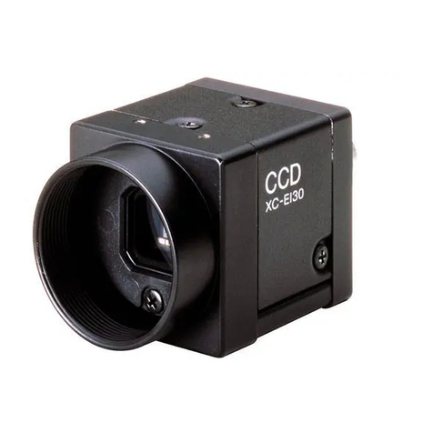
Sony XC-555 User manual

2002 Sony Corporation
CCD Color
Video Camera Module
XC-555/555P
A-B3C-100-11 (1)
Technical Manual

2
Table of Contents
Overview
Main Features ............................................................ 3
Connection Diagram ................................................. 4
Location of Parts and Operation.............................. 5
Mode Setting .............................................................. 6
Installation ................................................................. 7
Connections............................................................... 9
Genlock ...................................................................... 9
RS-232C Command List
Functions That can be Controlled via the RS-232C
Interface ................................................................. 10
Precautions to be Observed When Using RS-232C
Commands ............................................................ 11
Setting the RS-232C Switches ............................... 11
Connections............................................................. 12
Communication Specifications .............................. 12
The Sequence from “Power up” to Beginning/
End of Communication......................................... 13
Camera Function Setting Commands ................... 14
Setting Gain.............................................................. 14
Shutter Settings ........................................................ 14
White Balance Settings ............................................ 15
Video Process Setting .............................................. 16
System Settings ....................................................... 16
Camera Setup Readout from a List ......................... 17
Examples.................................................................. 18
RS-232C Mode and the Memory Banks ................. 19
Structure of the Memory Banks................................ 19
Functions Available with Memory Load/Save ........... 20
The Memory Bank to be Activated When Power is
Turned on .............................................................. 20
Appendix
Shutter Speed and the Settings Command .......... 21
Specifications .......................................................... 25
Dimensions .............................................................. 26
Spectral Sensitivity Characteristics
(Typical Value) ....................................................... 27
XC-555 ..................................................................... 27
XC-555P ................................................................... 27

3
Overview
Overview
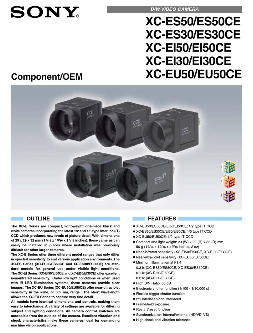
The XC-555/555P is an ultra-small color camera
module that utilizes a 1/2- type Charge Coupled
Device.
Main Features
Ultra-small size and lightweight
The camera is so small and light that you can install it
anywhere: even in locations where conventional video
cameras cannot be installed.
High resolution
A built-in Super HAD (Hole Accumulated Diode)
sensor, allows high sensitivity, low smear images. You
can shoot, even under poor lighting conditions.
High sensitivity
With a CCD offering 380,000 effective pixels, high-
resolution images can be obtained.
Four white balance adjustment modes
Using the white balance DIP switches, you can choose
from among four white balance modes (3200K/5600K/
ATW/MAN) to choose the best settings for shooting
conditions, and the most appropriate color
compensation.
Electronic shutter with a wide range of
operating speeds
Using the electronic shutter DIP switches, these levels
of shutter speed (OFF, 1/1000, and FLICKERLESS)
are available to allow you to match the shutter speed to
the shooting conditions.
When you set the DIP switches for the CCD IRIS
function, the shutter speed is adjusted automatically,
based on the amount of light allowed to enter, ensuring
the most appropriate level of image signal.

4
Overview
Connection Diagram
NF mount lens
VCL-03S12XM
VCL-06S12XM
VCL-12S12XM
VCL-12SXM (***)
C mount lens (Manual iris)
LO-999ERK
(C-mount adaptor)
LO-999CMT
(*****)
LO-77ERK
(Macro ring kit)
12P 12P
CCXC12P02N
05N
10N
25N
DC12 V
(#Pin#2&G)
VIDEO
JB-77
DC12 V
BNC
BNC
VIDEO
HD/VD
DC-700
AC
VIDEO
HD/VD

5
Overview
Location of Parts and Operation
1Dip switches for setting functions
This switches are used to adjust white balance and
shutter speed; and to flip AGC (ON/OFF) and output
signals (Y/C/VBS).
For details, see “Mode Setting” on page 6.
2R control for manual white balance adjustment
This control is effective when the white balance
switches are set to MAN. Adjust the red color by
turning the control.
3B control for manual white balance adjustment
This control is effective when the white balance
switches are set to MAN. Adjust the blue color by
turning the control.
1
2
3
4
5
4Lens mount (special mount)
5DC IN/SYNC/VIDEO connector (multi 12-pin)
This connector inputs DC 12V power and outputs the
video signal when the CCXC-12P02N/12P05N/
12P10N/12P25N camera cable is connected.
If the unit is connected to devices that originate a
synchronized signal, the external synchronous signal
(VS, HD/VD) can be used to move the color camera
module.

6
Overview
Pin assignment of the DC IN/SYNC/VIDEO
connector
Signal
Sync signal types
External Sync signal
Internal Sync
Pin No.
HD,VD VS Input
signal
1GND (Earth) GND (Earth) GND (Earth)
2+12V +12V +12V
3
VBS/Y Output (Earth) VBS/Y Output (Earth) VBS/Y Output (Earth)
4
VBS/Y Output (signal) VBS/Y Output (signal) VBS/Y Output (signal)
5HD Input (Earth) - -
6 HD Input (signal) - -
7VD Input (signal) VS Input (signal) -
8GND (–/C) GND (–/C) GND (–/C)
9–/C Output (signal) –/C Output (signal) –/C Output (signal)
10 RS-232C (TXD) *
11 RS-232C (RXD) *
12 VD Input (Earth) VS Input (Earth) GND
RS-232C (Earth)
Mode Setting
By flipping the DIP switches located on the side of this
camera, you can adjust the following functions.
Note
Each switch is assigned to the function. The switches
that should be set for a certain function (white balance,
shutter speed, AGC (Auto Gain Control), switching of
output signals(Y/C/VBS)) are specified. The effective
switches are indicated by shade in the illustrations.
To Adjust the white balance
Select the white balance setting according to the
lighting conditions.
Lighting condition DIP switch setting
For indoor shooting under
incandescent light (factory
setting).
For outdoor shooting on sunny
days.
The white balance is adjusted
according to the color
temperature transition of the
subject. This mode is suitable
for shooting with variable
lighting.
Select this position when you
want to adjust the red color
with the R control and the blue
color with the B control.
3200K
(fixed)
5600K
(fixed)
ATW
(auto tracing
white balance)
MAN
(manual)
1····6
1····6
1····6
1····6

7
Overview
Installation
Usable Lenses
•VCL-12S12XM NF mount lens (f=12mm)
•VCL-06S12XM NF mount lens (f=6mm)
•VCL-03S12XM NF mount lens (f=3.5mm)
•VCL-12SXM NF mount lens (f=12mm)
•C-mount lens for 1/2-inch CCD.
To adjust the shutter speed
Set the shutter speed switches to select the desired
shutter speed.
Using the CCD IRIS function, set the CCD IRIS mode.
Shutter speed DIP switch setting
OFF
1/1000
CCD IRIS
FLICKERLESS
1/60 sec. (factory setting)
(XC-555)
1/50 sec. (factory setting)
(XC-555P)
1/1000 sec.
Set the CCD IRIS mode.
1/100 sec. (XC-555)
1/120 sec. (XC-555P)
AGC (Auto Gain Control) ON/OFF
Gain DIP switch setting
1····6
1····6
1····6
1····6
ON
OFF
Auto gain control
(factory setting)
0 dB
Y/C/VBS
Select the camera output signal.
Output signal DIP switch setting
1····6
1····6
Y/C
VBS
Select this position to output
the Y/C separated signal from
the DC IN/VIDEO connector.
Select this position to output
the VBS signal from the DC IN/
VIDEO (factory setting).
1····6
1····6
Notes
•To attach a C-mount type lens, the C-mount adaptor
(LO-999CMT) is required.
• This camera uses a 1/2-inch CCD. So the lens should
be used with this size of CCD. If used with a lens
intended for 2/3-inch CCD, the angle of view will be
different.
•When connecting a heavy lens, make sure that it is
supported properly.
• When connecting heavy lens, make sure that it is not
subject to shocks or vibration.
Lens mount shoulder
4.1 mm
or less

8
Overview
To attach a lens To install the camera on a tripod
1Remove the lens mount cap by turning it
counterclockwise.
2Screw the C-mount adaptor (LO-999CMT) into the
lens mount of the camera. (only when using a C-
mount lens)
3Screw the lens.
When you have finished installation,
tighten the screws to secure the module.
When mounting the camera on a tripod, use the
supplied tripod adaptor.
1Assemble the tripod adaptor parts.
2Mount the video camera module on the tripod
adaptor.
1
2
3

9
Overview
Connections
An example of the assembly of the DC700/DC700CE
Camera Adaptor.
Genlock
The color video camera module is designed so that
internal sync and external sync are switched
automatically. When the color video camera module
receives the following external sync signal, the camera
is synchronized to that external sync signal.
Input signal
HD/VD, VS
Output signal
DC-700
Notes
•Make sure to turn off the power to the units you are
connecting or their components may be damaged.
•When disconnecting the cord, pull it out by the plug.
Never pull the cord itself.
• Connect the power cord after completing all other
connections.
WEN
TRIG
HD
VD/SYNC
AC IN
1
12
2
CAMERAVIDEO
Color video camera module
to DC/IN/SYNC/VIDEO connector
CCXC-12P02N/12P05N/
12P10N/12P25N
VBS out
Y/C out
The Signal is horizontally synchronized with
an HD signal externally input and is vertically
synchronized with an VD signal externally
input.
The burst signal is not externally
synchronized.
Same as above
Notes
•Use a synchronous signal specified by this Technical
Manual. For details on the specifications, see page
25.
•You cannot input a VBS signal to the camera as a
synchronous signal.

10
RS-232C Command List
Use of RS-232C control software which has been
developed based upon this command list may cause
malfunction or damage to hardware and software.
Sony Corporation is not liable for any such damage.
You can control various camera functions externally
by sending commands via the camera’s RS-232C I/F
(interface). Because the camera is equipped with
internal memory, setting values for various functions
input via RS-232C commands can be saved. The
memory is not volatile memory, so the information
will be preserved, even if the power to the camera is
turned off, enabling you to use the camera with the
same settings, and in the same way, both before and
after the power is cut off restored.
Functions That can be Controlled via the RS-
232C Interface
You can control the following functions using the program developed according to this command list.
AGC : ON/OFF
AGC Max Gain : 6, 12, 18dB, 3 levels
Step Gain : 0 to 18 dB, in 1 dB steps
Shutter mode : OFF/CCD Iris/Variable/STEP
Shutter speed (Variable) : 1/50 (PAL), 1/60 (NTSC) to 1/100,000 sec.
CCD Iris Max Speed : 1/250 to 1/1000,000 sec., 9 levels (Operation guaranteed to 1/4,000 sec.)
Exposure correction : Approx. –1EV to +0.5 EV
AE speed : 3 levels
WB mode : AWB/ATW/Manual/3200K/5600K
AWB : One Push AWB start
ATW speed : 3 speeds
R, B-gain : Manual White Balance
Pedestal : Black level Brightness
Sharpness : Adjustment by contour compensation
Gamma : ON/OFF
Nega : ON/OFF
Output : VBS/YC
H-phase : External synchronization based on amount of H-delay
Mem.Load : Factory/A/B 3 types of settings loaded
Mem.Save : A/B 2 types of settings saved

11
RS-232C Command List
1
2
3
456
7
8
9
10
11 12
Precautions to be Observed
When Using RS-232C
Commands
•When the unit is shipped from the factory, the RS-
232C input item is set to [OFF]. To send RS-232C
commands to the camera, flip the DIP-switch to
[ON]. For details, refer to “Setting the RS-232C
switch” in the next column.
Changing the setting of the RS-232C switch falls
under the heading of dismantling the camera, and
is outside the scope of the warranty. To change the
setting, request assistance from the dealer from
whom you purchased your camera.
•When toggling the RS-232C Input/Output function
on and off, and when connecting the camera and a
host computer, be sure perform any operations only
after shutting off the power of both the camera and
the host computer.
•When controlling the camera using the RS-232C
feature, the DIP switches on the camera and the R/B
adjustment volume settings are disabled.
•Use only the Sony DC-700/700CE power adaptors.
The DC-77RR/77RRCE, DC-777/777P, CMA-D2/
D2CE, and CMA-D2MD adaptors cannot be used.
•Keep in mind the following with respect to the RS-
232C TXD and RXD connectors:
–Do not allow the voltage applied to exceed a
margin of +/– 10V with the RXD (pin 11 of the 12
multi-connector).
–The signal level output from the TXD (pin 10 of
the 12 multi-connector) is within +/– 5.4V (TYP).
Do not apply external voltage.
RXD TXD
Setting the RS-232C
Switches
Warning
Be aware that changing the setting of the RS-232C
switches falls under the heading of dismantling the
camera, and anything beyond this change of settings,
carried out by a Sony-authorized repair department
(company), is outside the scope of the warranty.
Notes
•Be sure to make these changes only after turning off
the power to the camera.
• In order to keep dust from adhering to the light-
receptor surface of the CCD, attach the lens mount
cap, etc., beforehand.
1Detach the 12-pin cable from the camera.
2Using a Philips screwdriver, remove the Philips
screws (7) from the camera.
At this point, the head block may fall out because
of elasticity of wires attached to the CCD head
block. Take care to avoid this.
3Push the rear panel to which the 12-pin connector
is attached about 3 mm into the frame of the
camera. The hidden RS-232C DIP switches will
become visible in the little window provided to
carry out DIP switch operations.
4Switch both of the last two switches on the left end
of the row to the down position.

12
RS-232C Command List
XC-555/P
12 pin Connector
1 GND
2 +12 V
3 GND
4 VBS/Y out
5 GND
6–/HD in
7 VS/VD in
8 GND
9–/C out
10 TXD (RS-232C)
11 RXD (RS-232C)
12 GND
PC
D-SUB 9P
CD 1
RXD 2
TXD 3
DTR 4
GND 5
DSR 6
RTS 7
CTS 8
RI 9
5Push the back panel and the CCD head block back
into their previous positions, and tighten the
Philips screws ( 7) to a torque of 0.18 N•m.
Connections
Communication
Specifications
This unit utilizes an RS-232C-compliant, flow
controlled, synchronous serial interface.
Because the RS-232C setting is set to OFF when the
unit is shipped from the factory, you must change the
setting of the internal DIP switches to utilizes the RS-
232C function. (Before changing the settings make
absolutely sure that the power to the unit is turned off.
(See “Setting the RS-232C Switches” (page 11).))
The parameters are as follows.
Communication speed : 9600 bps
Data length : 8 bit
Stop bit : 1 bit
Parity : None
This is a no-flow-control, no-handshake protocol, each
bite is transmitted from the LSB line.
Characters that can be transmitted are ASCII codes
30h to 39h, 41h to 5Ah (Alphabetic capital letters A to
Z, Arabic numerals 0 to 9), a space (20h), and a
Carriage Return (0Dh).
Thus the commands used to control the camera are
made up of the character set specified above, and each
command must end with a Carriage Return character
(0Dh).
Because this is a no-flow-control protocol, to prevent
communication overflows, if the host side sends one
byte, before sending the next byte, insert a 1 ms stop
period.

13
RS-232C Command List
The Sequence from
“Power up” to
Beginning/End of
Communication
Commands expressed in writing as alphabetic letters
are always enclosed in brackets [ ], and Carriage
Return is abbreviated. For example, what is written on
the page as [12AB] is sent as 31h, 32h, 41h, 42h, and
0Dh in data.
1Immediately after the power is turned on, the
camera makes the required settings based on
information stored in non-volatile memory, and the
camera begins to start up.
At this point in time, RS-232C communication is
not permitted.
2After start-up is completed, the camera sends
[ACTV] to the host.
After the host has received this [ACTV]
transmission, send your commands to the camera.
3Send the version confirmation command [VERS]
from the host.
Based on this, the camera enters the RS-232C
mode.
4The camera sends its software version information
[X1**] 1) and [OKAY]to the host.
1) [X] indicates that this is an XC series camera.
[1] is a product code that indicates this is an XC-555. A [2]
would indicate an XC-555P.
[**] indicates the version of the software. [10] in place of
** would indicate Version 1.0.
5After the [OKAY] is sent in step 4, the camera is
able to receive setting change commands from the
host, and it waits for communication.
6Send a command from the host.
7The camera receives the command, and when
execution is complete, it returns an [OKAY]. (For
all commands except the One Push AWB
command.)
If a receive error or a command error occurs,
[CERR] is returned from the camera.
Do not send the next command from the host until
an answering (Ack) [OKAY] or [CERR] is
received from the camera.
8If you send a [STOP] from the host, the camera
returns an [OKAY], then it exits the RS-232C
mode and re-enters the normal operating mode.
(That is, it returns to the state it was in after step 1,
above.)

14
RS-232C Command List
Camera Function
Setting Commands
Setting Gain
AGC ON/OFF
Applicable to both AGC Max Limit and STEP gain.
AGC Max Limit (AGC ON)
6dB [E220]
12dB [E221]
18dB [E222]
AE speed
Also applicable to CCD Iris
Slow [EB00]
Norm [EB02]
Fast [EB04]
STEP Gain (AGC OFF)
0dB [E200]
1dB [E201]
2dB [E202]
: :
15dB [E20F]
16dB [E210]
17dB [E211]
18dB [E212]
Exposure Correction
Also applicable to CCD Iris
Over Max [A2FF]
: :
Standard [A280]
: :
Under Max [A201]
Shutter Settings
Shutter OFF
Send two commands together, in a [E3**], [E4**]
order, one after the other.
(The camera returns an [OKAY] after each and every
command.)
Shutter OFF [E300][E400]
CCD Iris ON & Max Limit
Send two commands together, in a [E3**], [E4**]
order, one after the other.
(The camera returns an [OKAY] after each and every
command.)
CCD Iris ON (Max 1/250) [E360] [E400]
CCD Iris ON (Max 1/500) [E360] [E401]
CCD Iris ON (Max 1/1000) [E360] [E402]
CCD Iris ON (Max 1/2000) [E360] [E403]
CCD Iris ON (Max 1/4000) [E360] [E404]
CCD Iris ON (Max 1/10000) [E360] [E405]
CCD Iris ON (Max 1/20000) [E360] [E406]
CCD Iris ON (Max 1/50000) [E360] [E407]
CCD Iris ON (Max 1/100000) [E360] [E408]
However, operation is guaranteed up to 1/4000.
AE speed
Also applicable to AGC
Slow [EB00]
Norm [EB02]
Fast [EB04]
Exposure Correction
Also applicable to AGC
Over Max [A2FF]
: :
Standard [A280]
: :
Under Max [A200]

15
RS-232C Command List
Flicker Less ON
Send two commands together, in a [E3**], [E4**]
order, one after the other.
(The camera returns an [OKAY] after each and every
command.)
Flicker Less ON [E328] [E401]
Shutter speed (STEP)
Send two commands together, in a [E3**], [E4**]
order, one after the other.
(The camera returns an [OKAY] after each and every
command.)
1/60 (PAL 1/50) [E328][E400]
FL [E328][E401]
1/250 [E328][E403]
1/500 [E328][E404]
1/1000 [E328][E405]
1/2000 [E328][E406]
1/4000 [E328][E407]
1/10000 [E328][E408]
1/20000 [E328][E409]
1/50000 [E328][E40A]
1/100000 [E328][E40B]
Shutter speed (Variable)
Send two commands together, in a [E3**], [E4**]
order, one after the other.
(The camera returns an [OKAY] after each and every
command.)
Shutter speed NTSC PAL
Slow 1/50 – [E348] [E400]
: : – : :
: 1/59.7 – [E348] [E432]
: 1/60 [E348] [E432] [E348] [E433]
: : : : : :
: 1/120 [E348] [E4B5] [E348] [E4B5]
: : : : : :
: 1/1000 [E349] [E428] [E349] [E428]
: : : : : :
Fast 1/100000 [E349] [E4FF] [E349] [E4FF]
For details on the shutter speed, see “Shutter Speed
and the Settings Command” on page 21.
White Balance Settings
WB mode (AWB/ATW/Manu/3200K/5600K)
AWB [EA30](One Push AWB)
ATW [EA31]
Manu [EA33]
3200K [EA34]
5600K [EA35]
One Push AWB
start [C800]
One Push AWB: Starts after the image is taken with
the appropriate exposure when a
white object fills the entire screen.
AWB Answer (Acknowledgement (Ack)
returned from the camera in response to a
One Push AWB)
OK [C208] AWB Finished Normally
NG [C018] Automatic adjustment not possible due to
unacceptable level of accuracy
Level Hi [C003] Exposure too bright
Level Lo [C004] Exposure too dark
Ctemp Hi [C005] Light source color temperature too high
Ctemp Lo [C006] Light source color temperature too low
From the time [C800] is received, until Answer Back
is sent, a delay of a maximum of as long as
approximately 10 seconds may occur. During that
period, do not send commands from the host.
ATW speed
slow [EB31]
norm [EB32]
fast [EB33]

16
RS-232C Command List
R,B-gain (Effective only when WB mode =
Manu)
R-gain Min. [A000]
: :
Standard [A080]
: :
R-gain Max. [A0FF]
B-gain Min. [A100]
: :
Standard [A180]
: :
B-gain Max. [A1FF]
Video Process Setting
Pedestal
Pedestal Min. [AD71]
: :
Standard [AD80]
: :
Pedestal Max. [AD8F]
Note
The settings that can actually be made are limited to 16
levels, including [AD80h].
Gamma ON/OFF
ON [E880]
OFF [E800]
Sharpness
Sharpness Min. [A500]
: :
Standard [A580]
: :
Sharpness Max. [A5FF]
Nega/Posi
posi [EAB1]
nega [EAB0]
The operation of AGC, CCD Iris, AWB, and ATW is
not guaranteed when nega is set.
System Settings
Memory Load Factory/Bank A/Bank B
Load Factory [EF12]
Load from A [EF00]
Load from B [EF01]
Memory Save Bank A/Bank B
Save to A [EBFA]
Save to B [EBFB]
Output Sel. VBS/YC
VBS [EA81]
YC [EA80]
H-Phase
Shift –Max [A400]
: :
Standard [A480]
: :
Shift +Max [A4FF]
Only effective when the camera is operated with
external synchronization. Other than that, the camera
returns a [CERR].

17
RS-232C Command List
Camera Setup Readout from a
List
Read Request [RMEM]
Sends the relative address and the data, in order, from
the beginning of the Camera Setup Memory area.
Host Computer Camera
[RMEM] t
T[S00_**] ** are assumed to be 8bit(LSB: b0) b1=0: AGC OFF,
b1=1: AGC ON
b3=0: Shutter Manual, b3=1: Shutter Auto
T[S01_**] ** = AGC Max Gain 00: 6dB, 01: 12dB, 02: 18dB
T[S02_**] ** = Gain 00: 0dB – 12h: 18dB
T[S03_**] ** = AE Compensation 00: under – 80h: Standard – FFh: over
T[S04_**] ** = Shutter Speed(1) The first digit of the 00,01h Shutter Speed variable’s 3 digits
T[S05_**] ** = Shutter Speed(2) The last two digits of the 00 – FFh Shutter Speed variable’s 3 digits
T[S06_**] ** = [E3**]The last two digits of the most recently received [E3**] command
T[S07_**] ** = [E4**]The last two digits of the most recently received [E4**] command
T[S08_**] ** = CCD Iris Max Speed 00: 1/250 – 04h: 1/4000 – 08h: 1/100000
T[S09_**] ** = AE Speed 00: slow,02: norm,04: fast
T[S0A_**] ** = White Balance Mode 00: AWB,01: ATW,03: manual,04: 3200K,05: 5600K
T[S0B_**] ** = ATW Speed 01: slow,02: norm,03: fast
T[S0C_**] ** = R-Gain 00: min – 80h: Standard – FFh: max
T[S0D_**] ** = B-Gain 00: min – 80h: Standard – FFh: max
T[S0E_**]Not Defined
T[S0F_**]Not Defined
T[S10_**] ** = Pedestal 71h: min – 8Fh: Standard – FFh: max
T[S11_**] ** = Gamma 00: OFF, 80h: ON
T[S12_**] ** = Memory Bank 00: Factory, 01: Bank A, 02: Bank B
T[S13_**] ** = Sharpness 7Ah: min – 89h: Standard – FFh: max
T[S14_**]Not Defined
T[S15_**]Not Defined
T[S16_**] ** = Picture 00: Nega, 01: Norm
T[S17_**] ** = Output 00: Y/C, 01: VBS
T[S18_**] ** = H-Phase (VS mode) 00: Phase Delayed – 80h: Standard – FFh: Phase Advanced
T[S19_**] ** = H-Phase (HR/VR mode) 00: Phase Delayed – 80h: Standard – FFh: Phase Advanced
T[S1A_**]Not Defined
T[S1B_**]Not Defined

18
RS-232C Command List
Examples
Commands expressed in writing as alphabetic letters
are always enclosed in brackets [ ], and Carriage
Return is abbreviated. For example, what is written on
the page as [12AB] is sent as 31h, 32h, 41h, 42h, and
0Dh in data.
Setting RS-232C mode
1Set the RC-232C switches to ON (see “Setting the
RS-232C Switches” (page 11)).
2Connect the camera and the host
(see “Connections” (page 12)).
3Supply power to the camera.
4Confirm that [ACTV] has been sent from the
camera.
5Send the version confirmation command [VERS]
to the camera.
6Confirm that the version information [X1**]1) and
an [OKAY] have been sent from the camera.
1) [X] indicates that this is an XC series camera.
[1] is a product code that indicates this is an XC-555. An
XC-555P would send a [2].
[**] indicates the version of the software. If it is [10], the
version is Version 1.0.
After sending an [OKAY], the camera is able to
receive RS-232C commands, and it remains in a
wait state, watching for communication.
Setting AGC to ON
AGC is set to ON using the AGC Max Limit
command.
1Send the AGC Max Limit command (18dB),
[E222], to the camera.
2Confirm that an [OKAY] has been sent from the
camera.
Setting the Shutter speed to 1/2000
Send the two commands needed to set the shutter
speed together, one right after the other.
1Send the first half of the Shutter speed command
(STEP), [E328], to the camera.
2Confirm that an [OKAY] has been sent from the
camera.
3Send the second half of the Shutter speed
command (STEP), [E406], to the camera.
4Confirm that an [OKAY] has been sent from the
camera.
Activating One Push AWB
Set WB mode to AWB, then send the start command.
1Send the WB mode AWB command, [EA30], to
the camera.
2Confirm that an [OKAY] has been sent from the
camera.
3Send the AWB start command, [C800], to the
camera.
4Confirm that an [OKAY] has been sent from the
camera.
(One of the following will be returned.)
OK : [C208] AWB Finished Normally
NG : [C018] Automatic adjustment not
possible due to unacceptable
level of accuracy
Level Hi : [C003] Exposure too bright
Level Lo : [C004] Exposure too dark
Ctemp Hi : [C005] Light source color
temperature too high
Ctemp Lo : [C006] Light source color
temperature too low
Ending RS-232C mode
1Send the “end RS-232C mode” command, [STOP]
to the camera.
2Confirm that an [OKAY] has been sent from the
camera.
The camera will return to the same internal settings
it had when the power was first turned on.
3Confirm that an [ACTV] has been sent from the
camera.

19
RS-232C Command List
RS-232C Mode and the Memory Banks
Structure of the Memory Banks
The XC-555 is equipped with three Memory Banks
(Factory/A/B) to hold camera settings. Factory is “read
only,” holding the settings made when the camera was
shipped from the factory. A and B can be written to, as
well as read from, and the user utilizes these locations
to hold setting values, calling them up when needed.
When the camera is in operation, valid settings are
held in volatile memory. The user sends RS-232C
commands to change the camera settings, overwriting
the settings information held in these memory
locations.
Using the “Memory Save” command, setting
information can be written to either of the non-volatile
Memory Bank A or Memory Bank B locations.
Using the “Memory Load” command, the information
stored in Memory Banks Factory, A, or B, can be read
out.
When power to the camera turned on, the settings
information loaded with the most recent “Memory
Load” command is read out of memory, and used as
the current settings. (When the camera is shipped from
the factory, the information stored in the Memory
Bank Factory is set to be read out when power is
turned on.)
Settings made with the DIP switches on the side of the
camera or with the R/B adjustment volume are
recognized as the same as some of those held in the
Factory memory location. However, when “Memory
Load (Factory)” is carried out in RS-232C mode,
settings made with the DIP switches on the side of the
camera or with the R/B adjustment volume are
rendered invalid, and the settings are returned to those
made when the camera was shipped from the factory.
When the RS-232C switches hidden by the camera
cover are set to OFF, Memory Banks A and B are
disabled, so when power to the camera is turned on,
the camera starts up normally, using the settings stored
in Memory Bank Factory.
(This is the way the camera is shipped from the
factory.)
Host computer
DIP switches
RS-232C commands to
change settings
RS-232C ON
RS-232C OFF
Volatile memory
Activated settings
Read & Write
Read & Write
Read only
Non-volatile memory
Memory Bank A
Series A of settings
saved
When power to the camera turned on, the settings on “Factory” is
loaded automatically. (The AGC, Shutter, W.balance, and VBS/
YC settings made using the DIP switches or made using the R/B
adjustment volume are enabled. )
Memory Bank B
Series B of Settings
saved
Memory Bank Factory
Initial values set at the
factory

20
RS-232C Command List
Functions Available with
Memory Load/Save
Category Data Initial values
Gain AGC ON/OFF ON
AGC Max Gain 18dB
Step Gain 0dB
Shutter speed Shutter OFF/CCD Iris/ OFF
Variable
Shutter speed NTSC:1/60 PAL:1/50
CCD Iris Max Speed 1/4000
Exposure Exposure Compensation 80h : Normal Status
AE speed normal
White Balance WB mode AWB/ATW/ 3200K
manual/3200K/5600K
ATW speed normal
Manual R-gain 80h : Normal Status
Manual B-gain 80h : Normal Status
AWB R-gain1) –
AWB B-gain1) –
Video Process Pedestal 80h : Normal Status
Sharpness 80h : Normal Status
Gamma ON/OFF ON
Nega ON/OFF OFF
Output VBS/YC VBS
VS H-phase 80h : Normal Status
HD/VD H-phase 80h : Normal Status
1) AWB R,B-gain retains the results of the last One
Push AWB operation. If “Memory Load” is carried
out when WB mode is set to AWB, the AWB R, B-
gain results held in memory are activated.
The Memory Bank to be
Activated When Power is Turned
on
When the RS-232C switches are set to
OFF
The “Factory” settings are activated. The AGC,
Shutter, WB, and VBS/YC settings made using the
DIP switches on the side of the camera or made using
R/B adjustment volume are given priority.
When the RS-232C switches are set to ON
The settings in the Memory Bank (Factory/A/B)
selected in the last Memory Load operation are
activated.
If started using “Factory,” immediately after the power
is turned on, the AGC, Shutter, W.Balance, and VBS/
YC settings made using the DIP switches on the side
of the camera or made using R/B adjustment volume
are given priority. After that, if the camera enters RS-
232C mode, and “Memory Load Factory” is carried
out, settings made using the DIP switches on the side
of the camera or made using R/B adjustment volume
are disabled, and the initial values shown in “Functions
Available with Memory Load/Save” on the previous
column are activated.
Other manuals for XC-555
2
This manual suits for next models
1
Table of contents
Other Sony Security Camera manuals

Sony
Sony FCB-PV480 User manual

Sony
Sony HDC3500 User manual

Sony
Sony DynaView SSC-DC593 User manual

Sony
Sony RYK-AF302A User manual

Sony
Sony SNC-M3W User manual

Sony
Sony SNC-RZ25 User manual

Sony
Sony Effio E User manual

Sony
Sony Ipela DynaView SNC-DF50N User manual

Sony
Sony EVI-D70 User manual

Sony
Sony SNC-DH110 User manual

Sony
Sony SSC-FM560 User manual

Sony
Sony SNC-DH110T User manual

Sony
Sony FCBIX47C User manual

Sony
Sony Ipela SNC-RX530P User manual

Sony
Sony CD-7226 User manual

Sony
Sony MPEG4 LAN Camera User manual

Sony
Sony Ipela SNC-VB632D User manual

Sony
Sony XC-ST51 User manual

Sony
Sony SNCVM602R User manual

Sony
Sony XCD-SX900 User manual