SERVICE MANUAL
Sony Corporation
Published by Sony Techno Create Corporation
HT-ST9
SA-ST9
SPECIFICATIONS
HT-ST9
SOUND BAR
SA-ST9
ACTIVE SPEAKER SYSTEM
9-896-148-02
2015F33-1
© 2015.06
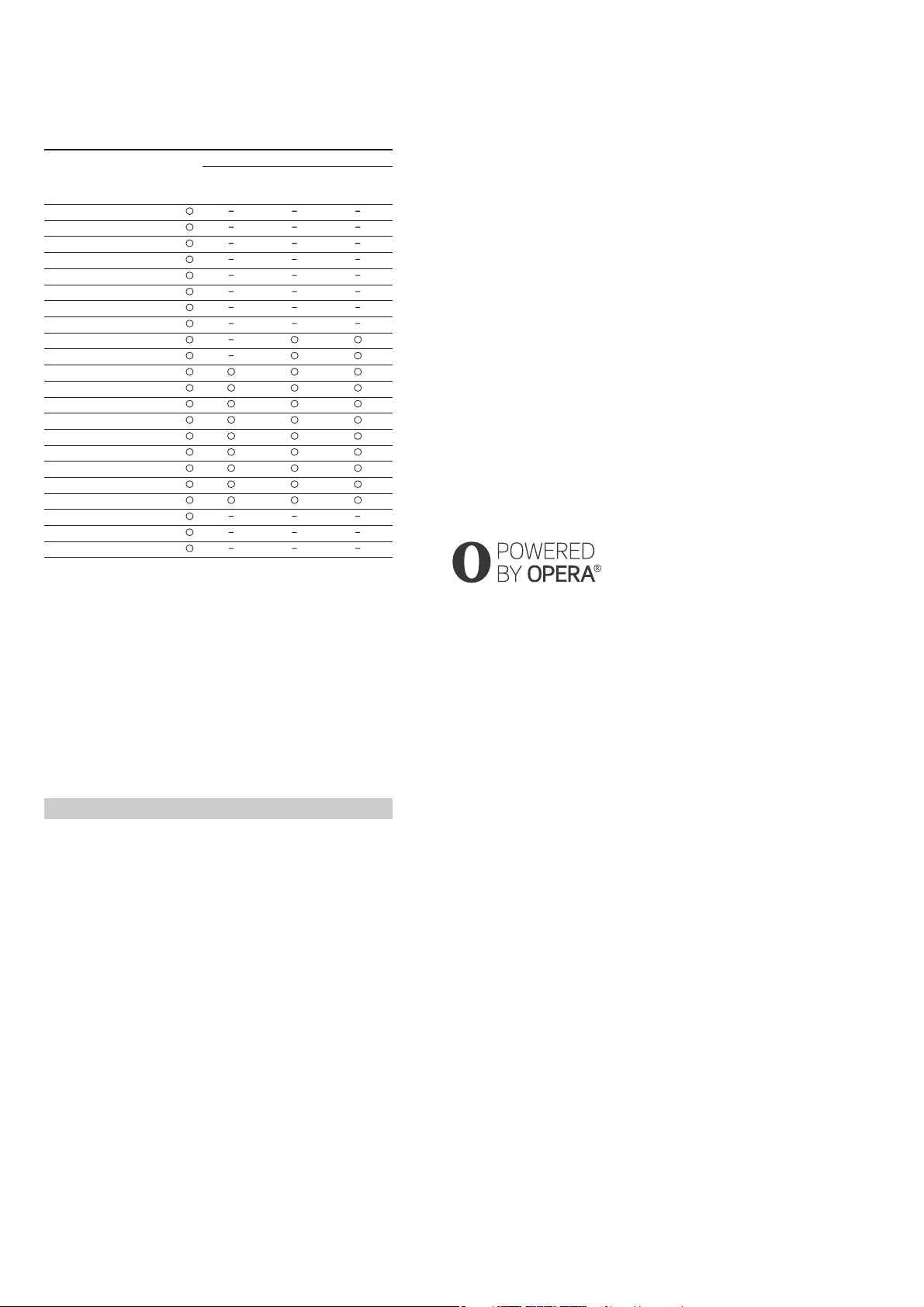
US Model
Canadian Model
AEP Model
UK Model
Australian Model
Chinese Model
Singapore Model
Taiwan Model
Latin American Model
Ver. 1.1 2015.06
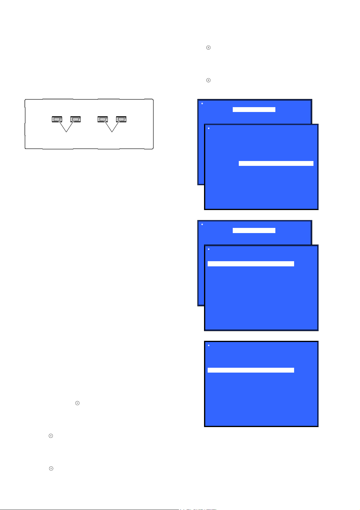
• All of the units included in the HT-ST9 (SA-
ST9/SA-WST9/Remote control) are required
to confirming operation of SA-ST9. Check in
advance that you have all of the units.
COMPONENT MODEL NAME
HT-ST9
Bar Speaker (Active Speaker System) SA-ST9
Subwoofer (Active Subwoofer) SA-WST9
• Please refer to service manual separately issued for Subwoofer.
Photo: SA-ST9
Note:
Be sure to keep your PC used for service and
checking of this unit always updated with the
latest version of your anti-virus software.
In case a virus affected unit was found during
service, contact your Service Headquarters.
Amplier section
U.S. models:
POWER OUTPUT AND TOTAL HARMONIC DISTORTION:
(FTC)
Front L + Front R:
With 6 ohms loads, both channels driven, from 200 - 20,000 Hz;
rated 25 Watts per channel minimum RMS power, with no more than
1% total harmonic distortion from 250 milliwatts to rated output.
POWER OUTPUT (reference)
Front L/Front R speaker blocks: 75 Watts (per channel at 6 ohms, 1 kHz)
Center speaker block: 75 Watts (per channel at 6 ohms, 1 kHz)
Center tweeter block: 75 Watts (per channel at 6 ohms, 10 kHz)
Canadian models:
Chinese model:
POWER OUTPUT (rated)
Front L + Front R: 45 W + 45 W
(at 6 ohms, 1 kHz, 1% THD)
POWER OUTPUT (reference)
Front L/Front R speaker blocks: 75 Watts (per channel at 6 ohms, 1 kHz)
Center speaker block: 75 Watts (per channel at 6 ohms, 1 kHz)
Center tweeter block: 75 Watts (per channel at 6 ohms, 10 kHz)
Inputs
HDMI IN 1*/2/3
DIGITAL IN (TV)
ANALOG IN
Output
HDMI OUT* (ARC)
* HDMI IN 1 and HDMI OUT (ARC) jacks support HDCP 2.2 protocol.
HDCP 2.2 is newly enhanced copyright protection technology that is
used to protect content such as 4K movies.
HDMI section
Connector
Type A (19pin)
USB section
(USB) port:
Type A (For connecting USB memory, memory card reader, digital still
camera)
LAN section
LAN (100) terminal
100BASE-TX Terminal
BLUETOOTH section
Communication system
BLUETOOTH Specication version 3.0
Output
BLUETOOTH Specication Power Class 1
Maximum communication range
Line of sight approx. 30 m (98.4 ft)1)
Maximum number of devices to be registered
9 devices
Frequency band
2.4 GHz band (2.4GHz - 2.4835 GHz)
Modulation method
FHSS (Freq Hopping Spread Spectrum)
Compatible BLUETOOTH proles2)
A2DP 1.2 (Advanced Audio Distribution Prole)
AVRCP 1.5 (Audio Video Remote Control Prole)
Supported Codecs 3)
SBC 4), AAC 5) , LDAC
Transmission range (A2DP)
20 Hz - 20,000 Hz (Sampling frequency 44.1 kHz)
1) The actual range will vary depending on factors such as obstacles
between devices, magnetic elds around a microwave oven, static
electricity, cordless phone use, reception sensitivity, the operating
system, software applications, etc.
2) BLUETOOTH standard proles indicate the purpose of BLUETOOTH
communication between devices.
3) Codec: Audio signal compression and conversion format
4) Subband Codec
5) Advanced Audio Coding
Front L/Front R speaker blocks
Speaker system
2-way coaxial speaker system, Acoustic suspension
Speaker
Woofer: 65 mm (2 5/8 in) cone type, Magnetic uid speaker
Tweeter: 18 mm (23/32 in) soft dome type
Center speaker block
Speaker system
Center
2-way coaxial speaker system, Acoustic suspension
Satellite
Full range speaker system, Acoustic suspension
Speaker (5 speakers)
Center
Woofer: 65 mm (2 5/8 in) cone type, Magnetic uid speaker
Tweeter: 18 mm (23/32 in) soft dome type
Satellite
65 mm (2 5/8 in) cone type, Magnetic uid speaker
POWER OUTPUT (rated)
Front L + Front R: 50 W + 50 W
(at 6 ohms, 1 kHz, 1% THD)
POWER OUTPUT (reference)
Front L/Front R speaker blocks: 75 Watts (per channel at 6 ohms, 1 kHz)
Center speaker block: 75 Watts (per channel at 6 ohms, 1 kHz)
Center tweeter block: 75 Watts (per channel at 6 ohms, 10 kHz)
POWER OUTPUT
Front L/Front R speaker blocks: 30 Watts (per channel at 6 ohms, 1 kHz)
Center speaker block: 30 Watts (per channel at 6 ohms, 1 kHz)
Center tweeter block: 30 Watts (per channel at 6 ohms, 10 kHz)
Other models:
Wireless LAN section
Standards Compliance
IEEE 802.11 a/b/g/n
Frequency band (Except Chinese model)
2.4 GHz, 5 GHz
Frequency band (Chinese model)
2.4 GHz - 2.4835 GHz
5.15 GHz - 5.35 GHz
5.725 GHz - 5.85 GHz
General
Power requirements
120 V AC, 60 Hz (US and Canadian models)
Power consumption
On: 60 W
Standby mode: 0.5 W or less
BLUETOOTH Standby mode: 0.5 W or less (Except AEP and UK models)
120 V AC, 50 Hz/60 Hz (Taiwan model)
220 V - 240 V AC, 50 Hz/60 Hz (Other models)
Dimensions (approx.) (w/h/d)
1,130 mm × 88 mm × 128 mm (44 1/2 in × 3 1/2 in × 5 1/8 in)
(without grille frame, without stands, including projection portion)
1,130 mm × 88 mm × 133 mm (44 1/2 in × 3 1/2 in × 5 1/4 in)
(with grille frame, without stands)
1,130 mm × 100 mm × 129 mm (44 1/2 in × 4 in × 5 1/8 in)
(without grille frame, with stands, including projection portion)
1,130 mm × 101 mm × 136 mm (44 1/2 in × 4 in × 5 3/8 in)
(with grille frame, with stands)
Mass (approx.)
6.8 kg (14 lb 15 7/8 oz) (without grille frame, without stands)
120 V - 240 V AC, 50 Hz/60 Hz (Latin American model)
Networked Standby (all wired network ports connected, all wireless
network ports activated): 7.3 W (AEP and UK models)
Communication system
Wireless Sound Specication version 3.0
Modulation method
DSSS
Wireless transmitter section
Compatible iPod/iPhone models
The compatible iPod/iPhone models are as follows. Update your iPod/
iPhone with the latest software before using with the system.
BLUETOOTH technology works with:
iPhone 6 Plus/iPhone 6/iPhone 5s/iPhone 5c/iPhone 5/iPhone 4s/
iPhone 4/iPhone 3GS
iPod touch (5th generation)/iPod touch (4th generation)
Frequency band (Russian model)
5.2 GHz (5.180 GHz - 5.240 GHz)
Frequency band (Chinese model)
5.15 GHz - 5.25 GHz
5.8 GHz (5.736 GHz - 5.814 GHz)
Frequency band (Latin American, Singapore and Taiwan models)
Frequency band (Other models)
5.2 GHz (5.180 GHz - 5.240 GHz)
5.8 GHz (5.736 GHz - 5.814 GHz)
– Continued on next page –