SERVICE MANUAL
Sony CONFIDENTIAL
For Authorized Servicer
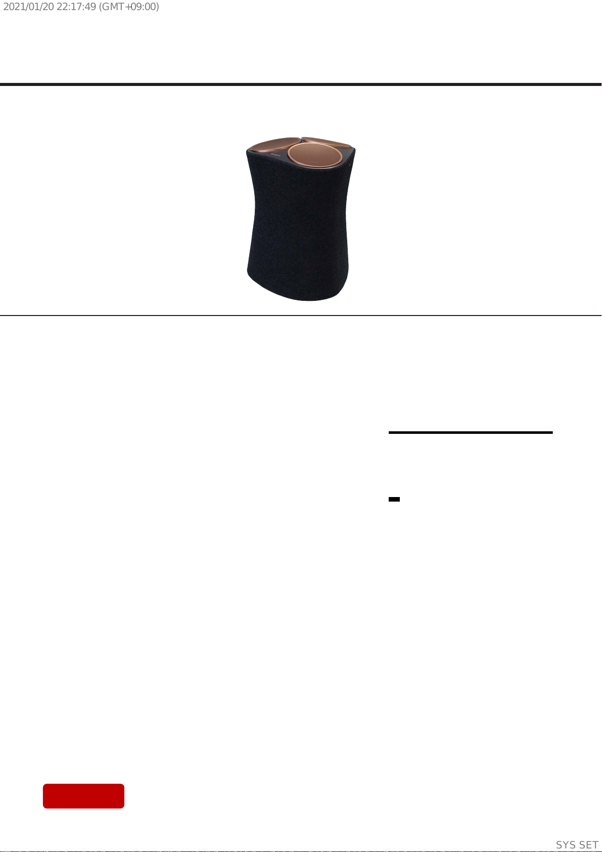
SRS-RA5000
SPECIFICATIONS
WIRELESS SPEAKER
US Model
Canadian Model
AEP Model
UK Model
E Model
Ver. 1.0 2021.01
Amplifier section (US, CND)
POWER OUTPUT AND TOTAL HARMONIC DISTORTION (USA models only):
Mid speaker L + R + C:
rated 8 W per channel minimum RMS power, with no more than
With 4 ohm loads, three channels driven, from 200 Hz - 20,000 Hz;
1% total harmonic distortion from 250 mW to rated output.
POWER OUTPUT (reference)
Up-firing/Mid speaker blocks: 30 W (per channel at 4 ohms, 1 kHz)
Subwoofer speaker block: 30 W (per channel at 4 ohms, 100 Hz)
Up-firing/Mid speaker section
Speaker system
Full Range Speaker system, Acoustic Suspension
Speaker diameter (approx.)
46 mm (1 13/16 in) × 3 / 46 mm (1 13/16 in) × 3
Subwoofer speaker section
Speaker system
Subwoofer Speaker system, Bass Reflex
Speaker diameter (approx.)
70 mm (2 7/8in) × 1
Input terminal section
Analog In
Wi-Fi section
Compatible standards
IEEE802.11 a/b/g/n
Radio frequency
2.4/5 GHz band
BLUETOOTH® section
Communication system
BLUETOOTH Specification version 4.2
Output
BLUETOOTH Specification Power Class 1
Maximum communication range
Line of sight approx. 30 m (98 ft)*1
Frequency band
2.4 GHz band (2.4000 GHz - 2.4835 GHz)
Compatible BLUETOOTH profiles*2
A2DP (Advanced Audio Distribution Profile)
AVRCP (Audio Video Remote Control Profile)
Supported Codec*3
SBC*4, AAC*5
Transmission range (A2DP)
20 Hz - 20,000 Hz (Sampling frequency 44.1 kHz)
*1The actual range will vary depending on factors such as obstacles between the
product and the device, magnetic fields around a microwave oven, static
electricity, reception sensitivity, antenna’s performance, operating system,
software application, etc.
*2BLUETOOTH standard profiles indicate the purpose of BLUETOOTH
communication between devices.
*3Codec: Audio signal compression and conversion format
*4Subband Codec
*5Advanced Audio Coding
General
Power requirements (Except LA)
DC 19.5 V
Power consumption
On: 55 W
Standby mode: 0.5 W or less (Power Saving mode)
(When BLUETOOTH/Network standby mode are
set to o)
Requisitos de alimentación (LA)
cc 19,5 V 6,2 A
Datos de alimentación del adaptador (suministrado)
Entrada: ca 100 - 240 V 50/60 Hz 1,4 A
Salida: cc 19,5 V 6,2 A
Standby mode: 2 W or less*6
(When BLUETOOTH/Network standby mode are
set to on)
Dimensions*7(approx.) (w/h/d)
235 mm × 329 mm × 225 mm (9 3/8in × 13 in × 8 7/8in)
Mass (approx.)
4.9 kg (10 lb 12 9/10 oz)
*6 The product will automatically enter Power saving mode when there is no
BLUETOOTH pairing history.
*7Not including projection portion
50 Hz/60 Hz power supply)
(using the supplied AC adapter connected to AC 100 V - 240 V,
Maximum output power (AEP, UK, RU)
2,400 MHz - 2,483.5 MHz < 19.9 dBm
5,150 MHz - 5,250 MHz < 18 dBm
5,250 MHz - 5,350 MHz < 18 dBm
5,470 MHz - 5,725 MHz < 18 dBm
5,725 MHz - 5,850 MHz < 13.98 dBm
Maximum output power (AEP, UK, RU)
< 9.9 dBm
Modulation method
FHSS
AC Adapter section (AEP, UK, RU)
Manufacturer’s name or trade mark
Sony Corporation
Commercial registration number
5010401067252
Address
1-7-1 Konan Minato-ku Tokyo, 108-0075 Japan
Model identifier
ACDP-120M01
What’s in the box
Wireless Speaker (1)
AC adapter (1)
AC power cord (1)* (Except AEP, UK, RU)
AC power cord (2) (AEP, UK, RU)
Operating Instructions (1)
AC plug adapter (1) (SP, LA)
Precautions/Specifications (1)
* The shape of the AC power cord varies depending
on the country or region.
Input voltage
100 V - 240 V
Input AC frequency
50 Hz/60 Hz
Output voltage - Output current - Output power
19.5 Vdc - 6.2 A - 120.9 W
Average active eciency
88.0%
Eciency at low load (10%)
88.2%
No-load power consumption
0.21 W
Design and specifications are subject to change without notice.
Compatible iPhone/iPod models
The compatible iPhone/iPod models are as follows. Update your
iPhone/iPod with the latest software before using with the product.
Made for:
iPhone X/iPhone 8 Plus/iPhone 8/iPhone 7 Plus/iPhone 7/iPhone SE/
iPhone 6s Plus/iPhone 6s/iPhone 6 Plus/iPhone 6/iPhone 5s/
iPod touch (6th generation)
Note
Sony cannot accept responsibility in the event that data recorded
to iPhone/iPod is lost or damaged when using your iPhone/iPod
connected to this product.
SYSSET
2021/01/2022:17:49(GMT+09:00)


