8
HCD-CZ1/NAS-CZ1
What is a FAVORITE PLAYLIST?
By registering tracks on your computer to a
favorite list using this system, you can play back
only the tracks you want to listen to. One
favorite playlist can be created for each profile,
and each favorite playlist can contain up to 100
tracks.
To register tracks to a favorite
playlist and playing
1
During the playback or play pause of the
desired track, press FAVORITE ADD.
“FAVORITE” appears.
2
After “FAVORITE” disappears, repeat step 1
to register the desired tracks.
Playing favorite playlist
1
Press NETWORK repeatedly to switch
the function to MUSIC LIBRARY.
2
Press FAVORITE CALL.
Play starts.
Tip
You can also play the favorite playlist through the
following procedure:
1. Press LIBRARY MODE repeatedly until “
(Playlist mode)” appears.
2. Press ALBUM +/– repeatedly until “FAVORITE”
appears.
To delete tracks from a favorite
list
1
Press Nor Xto play or pause the track you
want to delete from a favorite playlist.
2
Press FAVORITE DELETE.
“DELETE?” appears.
3
Press ENTER.
“Deleting” appears, then “Complete!”
appears.
Notes
•If you edit a track in an album that is registered to a
FAVORITE PLAYLIST on your computer, the track
is erased from the FAVORITE PLAYLIST
automatically. (except when you changed the track
name)
•During the playback of a track in a favorite playlist,
you cannot press FAVORITE ADD to register the
track to a favorite playlist.
•When you press FAVORITE DELETE, the track is
erased from the FAVORITE PLAYLIST but remains
in the Music Library.
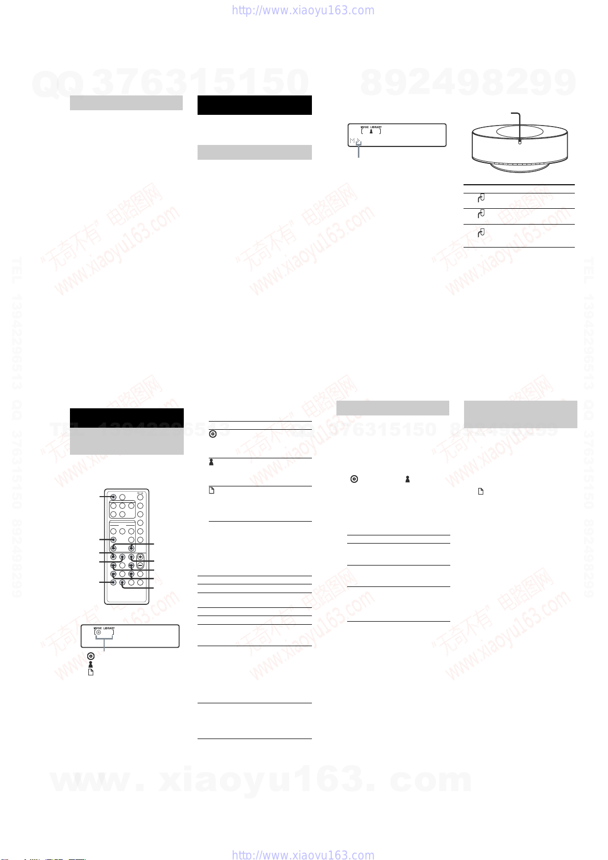
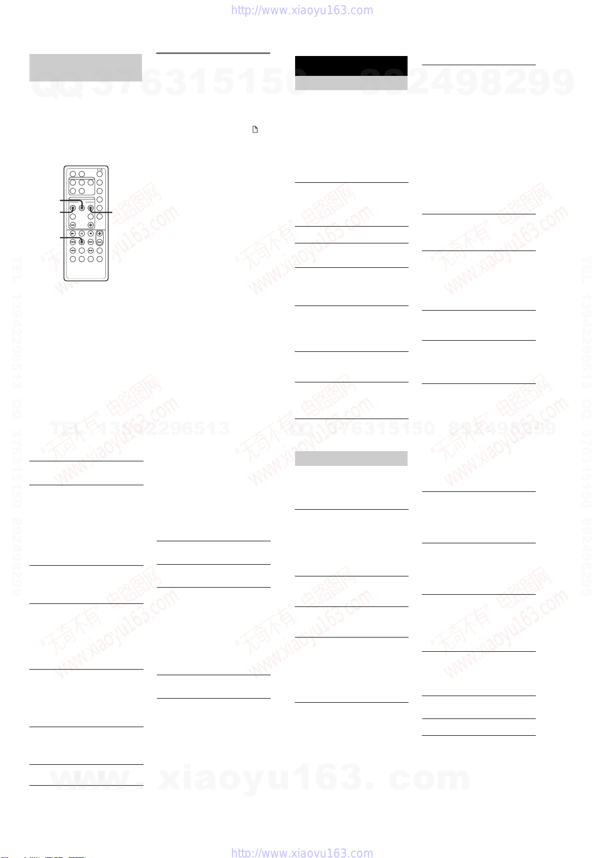
Listening to music in a
favorite list
–FAVORITE PLAYLIST Registration/
FAVORITE PLAYLIST Play
FAVORITE
DELETE
1
FAVORITE
CALL
ENTER
Should you encounter a problem with your
system, do the following:
1
Make sure the power cord is correctly and
firmly connected.
2
Find your problem in the troubleshooting
checklist below and take the indicated
corrective action.
If the problem persists after doing all of the
above, consult your nearest Sony dealer.
General
The display starts flashing as soon as you
plug in the power cord even though you have
not turned on the system (see step 2 of
“Connecting power cord” (page 13)).
Press ?/1 while the system is off. The
demonstration disappears.
The radio presetting is canceled.
Redo “Presetting radio stations” (page 24).
There is no sound.
Press VOL + or VOLUME + on the system.
Make sure the headphones are not connected.
There is severe hum or noise.
Move the system away from the source of noise.
Connect the system to a different wall outlet.
I nstall a noise filter (commercially available) to
the power cord.
The remote does not function.
Remove the obstacle.
Move
the remote closer to the system.
Point
the remote at the system’s sensor.
Replace the CR2025 battery.
Locate the system away from the fluorescent light.
The system can not be turned on even though
you have pressed ?/1.
Make sure the power cord is connected to a wall
outlet.
The color irregularity on a TV screen appears.
Turn off the TV set once, then turn it on after 15
to 30 minutes. If the color irregularity still
persists, place the speakers farther away from the
TV set.
Network
The desired server cannot be found.
•Check the network settings on your computer.
•Startup the server you want to use on your
computer.
•Check the network settings.
•Set the broadband router or hub again correctly.
For details, see the instruction manual of the
broadband router or hub.
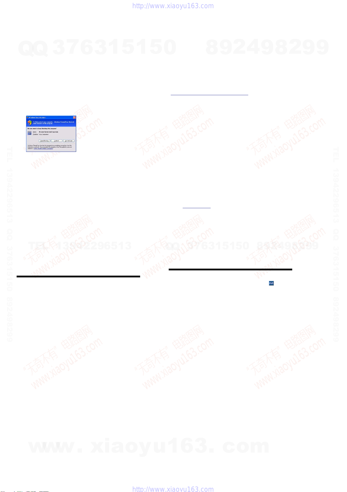
•Whensetting a firewall other than that provided
with the OS, refer to Troubleshooting in the
Installation Manual included on the supplied
CD-ROM.
•Reduce the number of servers that can be
connected to 10 servers or less (page 21).
•Replace the Ethernet cable with a new one.
•Follow the procedure below and reconnect to the
server.
1.
Select “MEDIA SERVERS?” in the network
menu (page 19), then press ENTER.
2.
Press ./> repeatedly to select the
desired media server, then press ENTER.
Tracks registered to a server cannot be
selected by the system.
•Track selection, playback and other operations on
the system side may not be possible for servers
other than M-crew Server (page 13).
The sound skips.
Sound skipping may occur in the following cases:
–When music is being recorded onto the server
–When the computer is running many
applications
–When the network status is crowded
–Whenmultiple systems are performing
playback simultaneously
Track names are not displayed.
•Some types of input characters cannot be
displayed by the system, even if they can be
registered and displayed on the server.
Operation commands take time.
•Depending on the condition of the server, it may
take a while until operation proceeds. For
example, when there is no response after pressing
m/M, keep pressing m/Mfor a while.
Afterwards, operation sould begin.
Troubleshooting
Problems and remedies
CD/MP3 player
Abnormal noise is produced.
•Check whether a disc that the system cannot play
is loaded.
Play does not start.
•Check whether a disc is loaded. The disc indicator
lights when a disc is loaded.
•Wipethe disc clean (page 34).
•Replace the disc.
•Place a disc that this system can play.
•Place the disc correctly.
•Remove the disc and wipe away the moisture on
the disc, then leave the system turned on for a few
hours until the moisture evaporates.
•PressNto start play.
The sound skips.
•Wipethe disc clean (page 34).
•Replace the disc.
•Try moving the system to a place without
vibration (e.g., on top of a stable stand).
MP3 audio track cannot be played back.
•Recording was not performed according to the
ISO9660 level 1 or level 2 format, or Joliet in the
expansion format.
•The MP3 audio track does not have the extension
“.MP3”.
•Thedatais not stored in MP3 format.
•Discscontaining files other than MPEG1, 2, 2.5
Audio Layer-3 files cannot be played.
MP3 audio tracks take longer to play back than
others.
•After the system reads all tracks on the discs,
playback may take more time than usual if:
–the number of albums or tracks on the disc is
very large.
–thealbumand track organization structure is
very complex.
The album title, track title and ID3 tag do not
appear correctly.
•Use a disc that conforms with ISO9660 level 1,
level 2, or Joliet in the expansion format.
•Thedisc ID3 tag is not ver. 1 or ver. 2.
Tuner
Severe hum or noise.
Stations cannot be received.
•Setthe proper band and frequency (page 24).
•Connect the antenna properly (page 11).
•Find a place and an orientation that provide good
reception, then set up the antenna again. If you
cannot obtain good reception, we recommend you
connect a commercially available external
antenna.
•The supplied FM lead antenna receives signals
along its entire length, so make sure you extend it
fully.
•Locate the antennas as far away from the speaker
cords as possible.
•Consult your nearest Sony dealer if the supplied
AM antenna has come off the plastic stand.
•Try turning off surrounding electrical equipment.
A stereo FM program cannot be received in
stereo.
•Press FM MODE until “MONO” disappears.
Optional components
There is no sound.
•Refer to General items “There is no sound.” and
check the condition of the system.
•Connect the component properly (page 30) while
checking:
–ifthecords are connected properly.
–if the cord plugs are firmly inserted all the way.
•Turn on the connected component.
•Refer to the operating instructions supplied with
the connected component and start playing.
•Press FUNCTION repeatedly to select
“ANALOG IN” (page 30).
The sound is distorted.
•Set
t
he volume of the connected component
lower.
If the system still does not
operate properly after performing
the above measures, reset the
system as follows:
1
Disconnect the power cord.
2
Reconnect the power cord.
3
Press ?/1 to turn on the system.
4
Press x, USER PROFILE 5 and POWER,
on the system at the same time.
The system is reset to the factory settings. You
should set the settings you made, such as the
preset stations.
If a message appears while using the system,
follow the procedures below to correct the
problem.
Network
Cannot Play
•The track cannot be played in the following cases:
–Sampling Rate is other than 32 kHz, 44.1 kHz,
48 kHz.
–The track is not being streamed by linear PCM.
–The track is other than one channel or two
channel.
–Thetrack sampling bits are other than 16 bits.
–Theserverstatus is busy.
Check Network
•Check
t
hat the Ethernet cable between the system
and the hub or router is firmly connected.
•Check that the hub or router is turned on.
IP Conflict
•Set the IP addresses of the system and other
devices on the network so that there is no
duplication (page 20).
No album
•Register the track as instructed by the operation
manual of the connected server.
•Follow the procedure below and reconnect to the
server.
1. Select “MEDIA SERVERS?” in the network
menu (page 19), then press ENTER.
2. Press ./> repeatedly to select the
desired media server, then press ENTER.
No Server
•Start up the server. M-crew Server can be started
up by the following method:
Right-click the task tray icon, then click “Start
Music Service” in the menu.
•M-crew Server may not be recognizing the
system. Follow the procedure below and check
whether M-crew Server is recognizing the system:
1. Click [Start] – [All Programs] – [M-crew
Server] – [TOOLS] – [EQUIPMENT LIST] in
that order.
2. If the server name is not present in the list that
appears in step 1, device registration must be
performed. For details, see the Help or Install
Manual within M-crew Server.
•Whensetting a firewall other than that provided
with the OS, refer to Troubleshooting in the
Installation Manual included on the supplied
CD-ROM.
•Perform the TCP/IP settings correctly for the
system and the computer (page 20).
Select Server
•Follow the procedure below and reconnect to the
server.
1. Select “MEDIA SERVERS?” in the network
menu (page 19), then press ENTER.
2. Press ./> repeatedly to select the
desired media server, then press ENTER.
Server Error
•Follow the procedure below and reconnect to the
server.
1. Select “MEDIA SERVERS?” in the network
menu (page 19), then press ENTER.
2. Press ./> repeatedly to select the
desired media server, then press ENTER.
Server Close
•Startup the server. M-crew Server can be started
up by the following method:
Right-click the task tray icon, then click “Start
Music Service” in the menu.
•When you want to change the computer’s network
settings, restart the server on this system. This
message disappears after a short time.
WebRadio Error
•Register a station that can be played back on M-
crew Server.
•Connection may be difficult depending on the
internet line status. Wait a bit and then perform the
operation again.
CD/MP3
No Disc
•Thereis no disc in the player.
Messages
w
w
w
.
x
i
a
o
y
u
1
6
3
.
c
o
m
Q
Q
3
7
6
3
1
5
1
5
0
9
9
2
8
9
4
2
9
8
T
E
L
1
3
9
4
2
2
9
6
5
1
3
9
9
2
8
9
4
2
9
8
0
5
1
5
1
3
6
7
3
Q
Q
TEL 13942296513 QQ 376315150 892498299
TEL 13942296513 QQ 376315150 892498299
http://www.xiaoyu163.com
http://www.xiaoyu163.com