Sony HCD-GS200 User manual

HCD-GS200
US Model
Canadian Model
SERVICE MANUAL
COMPACT DISC DECK RECEIVER
Sony Corporation
Home Audio Company
Published by Sony Engineering Corporation
9-874-022-03
2003J16-1
© 2003.10
HCD-GS200 is the Amplifier, CD player, Tape
Deck and Tuner section in MHC-GS200.
SPECIFICATIONS
Ver 1.2 2003. 10
Model Name Using Similar Mechanism HCD-GS300AV
CD CD Mechanism Type CDM64B-K1BD47A
Section Base Unit Name BU-K1BD47A
Optical Pick-up Name KSM-213BFN
TAPE Model Name Using Similar Mechanism HCD-GS300AV
Section Tape Transport Mechanism Type CMAL1Z221
— Continued on next page —
Amplifier section
U.S.A. models:
AUDIO POWER SPECIFICATIONS
POWER OUTPUT AND TOTAL
HARMONIC DISTORTION:
with 6 ohms loads both channels driven, from
120 – 10,000 Hz; rated 60 watts per channel
minimum RMS power, with no more than 10%
total harmonic distortion from 250 milliwatts to
rated output.
Continuous RMS power output
60 + 60 watts
(6 ohms at 1 kHz,
10% THD)
Total harmonic distortion less than 0.09%
(6 ohms at 1 kHz,
35 watts)
Inputs
VIDEO (MD) IN (phono jacks):
voltage 250 mV/450 mV,
impedance 47 kilohms
GAME (AUDIO) IN (phono jack):
voltage 450 mV,
impedance 47 kilohms
AUDIO IN (phono jacks): 450mV 47 kilohms
Outputs
PHONES (stereo phono jack):
accepts headphones of
8 ohms or more
FRONT SPEAKER: accepts impedance of 6 to
16 ohms
CD player section
System Compact disc and digital
audio system
Laser Semiconductor laser
(λ = 780 nm)
Emission duration:
continuous
Frequency response 2 Hz – 20 kHz (±0.5 dB)
Wavelength 780 – 790 nm
Signal-to-noise ratio More than 90 dB
Dynamic range More than 90 dB
OPTICAL OUT (CD)
(Square optical connector jack, rear panel)
Wavelength 660 nm
Output Level –18 dBm
Tape player section
Recording system 4-track 2-channel stereo
Frequency response 40 – 13,000 Hz (±3 dB),
using Sony TYPE I
cassette
Tuner section
FM stereo, FM/AM superheterodyne tuner
FM tuner section
Tuning range 87.5 – 108.0 MHz
Antenna FM lead antenna
Antenna terminals
North American model: 75 ohms unbalanced
Intermediate frequency 10.7 MHz
AM tuner section
Tuning range 530 – 1,710 kHz
(with the interval set at
10 kHz)
531 – 1,710 kHz
(with the interval set at
9 kHz)
Antenna AM loop antenna
Antenna terminals External antenna terminal
Intermediate frequency 450 kHz
w
w
w
.
x
i
a
o
y
u
1
6
3
.
c
o
m
Q
Q
3
7
6
3
1
5
1
5
0
9
9
2
8
9
4
2
9
8
T
E
L
1
3
9
4
2
2
9
6
5
1
3
9
9
2
8
9
4
2
9
8
0
5
1
5
1
3
6
7
3
Q
Q
TEL 13942296513 QQ 376315150 892498299
http://www.xiaoyu163.com

2
HCD-GS200
1. SERVICING NOTES ······················································· 4
2. GENERAL ·········································································· 5
3. DISASSEMBLY ································································ 7
3-1. Cabinet Top ··································································· 8
3-2. Front Cabi Assy ····························································· 8
3-3. Back Panel Assy ···························································· 9
3-4. MAIN Board ································································· 9
3-5. AMP Board ································································· 10
3-6. POWER Board ···························································· 10
3-7. Holder (LED-S), Bracket (Middle-R),
Power Bracket ····························································· 11
3-8. CD Mechanism Deck (CDM64B-K1BD47A) ············ 11
3-9. Base Unit (BU-K1BD47A),
D.SENSOR (OUT) Board, T.SENSOR Board ············ 12
3-10.D.SENSOR (IN) Board, LOAD SW Board,
L.T MOTOR Board ····················································· 12
3-11.CD LED Board ···························································· 13
3-12.BU Holder Assy ··························································· 13
3-13. CD Board ····································································· 14
3-14.Cassette Holder, Mech Deck (CMAL1Z221) ············· 14
3-15.Belt ·············································································· 15
3-16.DISPLAY Board ·························································· 15
3-17.KEY Board ·································································· 16
3-18.HEADPHONE Board, GAME LINK Board ··············· 16
3-19.DOOR LED Board ······················································ 17
4. TEST MODE ···································································· 18
5. MECHANICAL ADJUSTMENTS ····························· 19
6. ELECTRICAL ADJUSTMENTS ······························ 19
7. DIAGRAMS
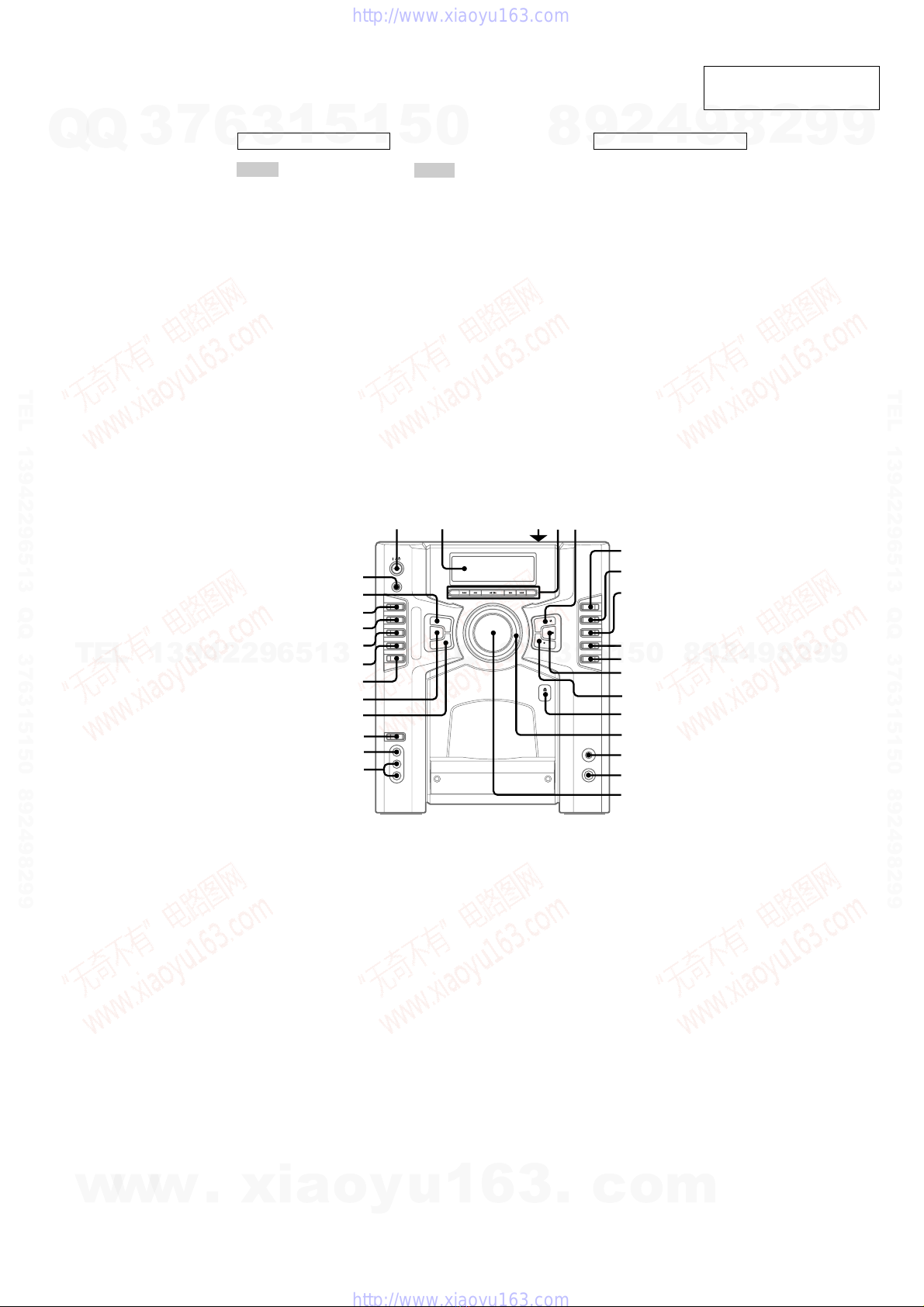
7-1. Circuit Boards Location ·············································· 23
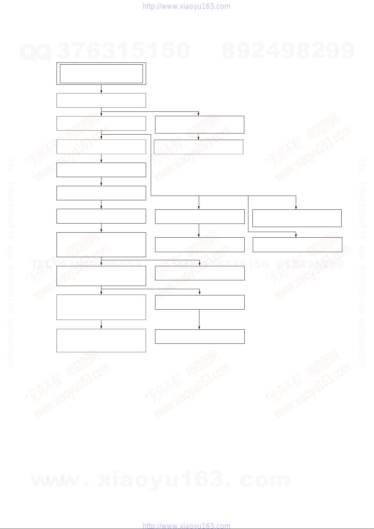
7-2. Block Diagrams ··························································· 24
– CD Section – ···························································· 24
– TUNER/TAPE Section – ·········································· 25
– AMP Section – ························································· 26
– DISPLAY/POWER Section –··································· 27
7-3. Printed Wiring Board – CD Section – ························ 28
7-4. Schematic Diagram – CD Section – ··························· 29
7-5. Printed Wiring Board
– CD MOTOR/SENSOR Section – ····························· 30
7-6. Schematic Diagram
– CD MOTOR/SENSOR Section – ····························· 31
7-7. Printed Wiring Board – MAIN Section – ··················· 32
7-8. Schematic Diagram – MAIN Section (1/3) – ············· 33
7-9. Schematic Diagram – MAIN Section (2/3) – ············· 34
7-10.Schematic Diagram – MAIN Section (3/3) – ············· 35
7-11.Printed Wiring Board – AMP Section – ····················· 36
7-12.Schematic Diagram – AMP Section – ························ 37
7-13.Printed Wiring Board – DISPLAY Section – ············· 38
7-14.Schematic Diagram – DISPLAY Section – ················ 39
7-15.Printed Wiring Board – POWER Section – ················ 40
7-16.Schematic Diagram – POWER Section – ·················· 41
7-17.IC Block Diagrams ······················································ 42
7-18.IC Pin Function Description ········································ 43
8. EXPLODED VIEWS
8-1. General Section ··························································· 48
8-2. Front Panel Section ····················································· 49
8-3. Chassis Section ···························································· 50
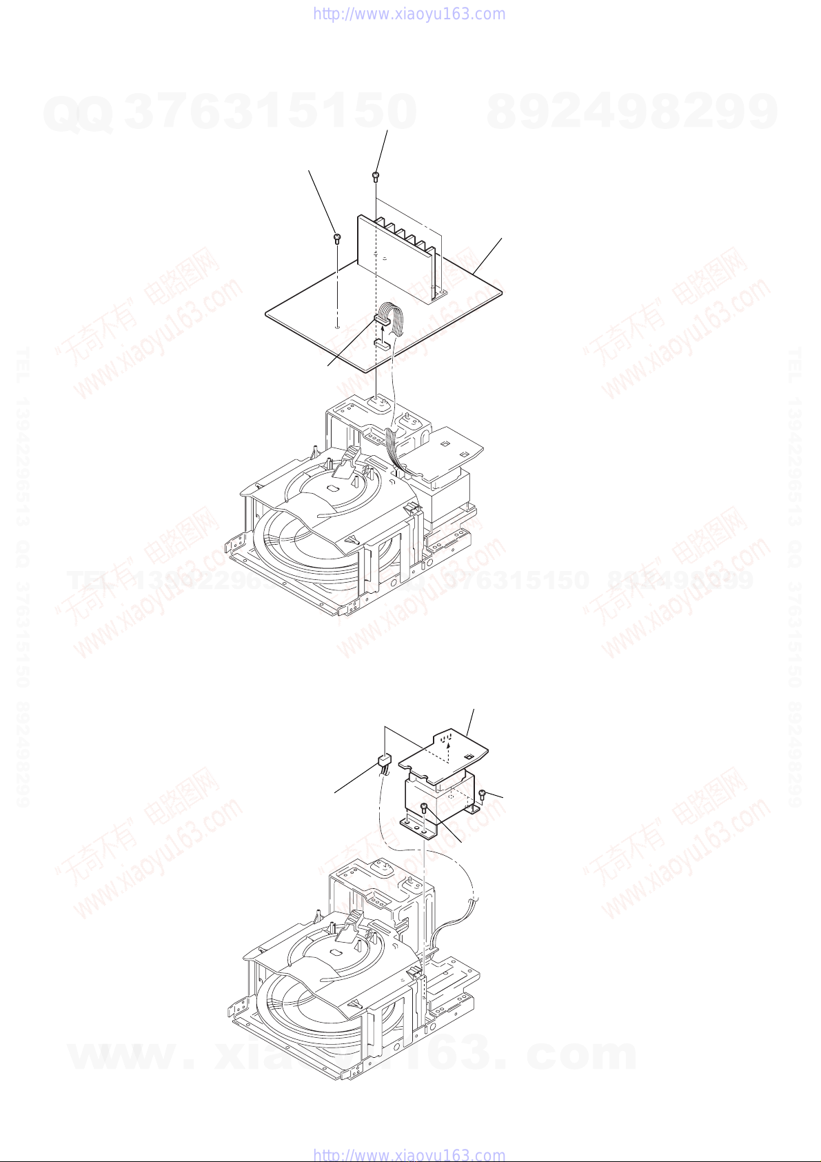
8-4. Mechanism Deck Section-1 (CDM64B-K1BD47A) ·· 51
8-5. Mechanism Deck Section-2 (CDM64B-K1BD47A) ·· 52
8-6. Base Unit Section (BU-K1BD47A) ···························· 53
9. ELECTRICAL PARTS LIST ······································· 54
TABLE OF CONTENTS
General
Power requirements 120 V AC, 60 Hz
Power consumption 120 watts
Dimensions (w/h/d) incl. projecting parts and controls
Approx. 280 ×325 ×
465 mm
Mass Approx. 8.7 kg
Supplied accessories: Remote commander (1)
Batteries (2)
AM loop antenna (1)
FM lead antenna (1)
Design and specifications are subject to change
without notice.
w
w
w
.
x
i
a
o
y
u
1
6
3
.
c
o
m
Q
Q
3
7
6
3
1
5
1
5
0
9
9
2
8
9
4
2
9
8
T
E
L
1
3
9
4
2
2
9
6
5
1
3
9
9
2
8
9
4
2
9
8
0
5
1
5
1
3
6
7
3
Q
Q
TEL 13942296513 QQ 376315150 892498299
http://www.xiaoyu163.com

3
HCD-GS200
SAFETY-RELATED COMPONENT WARNING!!
COMPONENTS IDENTIFIED BY MARK 0OR DOTTED LINEWITH
MARK 0ON THE SCHEMATIC DIAGRAMS AND IN THE PARTS
LIST ARE CRITICAL TO SAFE OPERATION. REPLACE THESE
COMPONENTS WITH SONY PARTS WHOSE PART NUMBERS
APPEAR AS SHOWN IN THIS MANUAL OR IN SUPPLEMENTS
PUBLISHED BY SONY.
Fig. A. Using an AC voltmeter to check AC leakage.
1.5 k
Ω
0.15
µ
FAC
voltmete
r
(0.75 V)
To Exposed Metal
Parts on Set
Earth Ground
SAFETY CHECK-OUT
After correcting the original service problem, perform the following
safety check before releasing the set to the customer:
Check the antenna terminals, metal trim, “metallized” knobs, screws,
and all other exposed metal parts for AC leakage.
Check leakage as described below.
LEAKAGE TEST
The AC leakage from any exposed metal part to earth ground and
from all exposed metal parts to any exposed metal part having a
return to chassis, must not exceed 0.5 mA (500 microamperes.).
Leakage current can be measured by any one of three methods.
1. A commercial leakage tester, such as the Simpson 229 or RCA
WT-540A. Follow the manufacturers’ instructions to use these
instruments.
2. A battery-operated AC milliammeter. The Data Precision 245
digital multimeter is suitable for this job.
3. Measuring the voltage drop across a resistor by means of aVOM
or battery-operatedAC voltmeter. The “limit” indication is 0.75
V, so analog meters must have an accurate low-voltage scale.
The Simpson 250 and Sanwa SH-63Trd are examples of a
passiveVOM that is suitable. Nearly all battery operated digital
multimeters that have a 2 VAC range are suitable. (See Fig.A)
CAUTION
Use of controls or adjustments or performance of procedures
other than those specified herein may result in hazardous
radiation exposure.
This appliance is classified as a CLASS 1 LASER product.
The CLASS 1 LASER PRODUCT MARKING is located on
the rear exterior.
Laser component in this product is capable of emitting radiation
exceeding the limit for Class 1.
The laser diode in the optical pick-up block may suffer electrostatic
break-down because of the potential difference generated by the
charged electrostatic load, etc. on clothing and the human body.
During repair, pay attention to electrostatic break-down and also
use the procedure in the printed matter which is included in the
repair parts.
The flexible board is easily damaged and should be handled with
care.
NOTES ON LASER DIODE EMISSION CHECK
The laser beam on this model is concentrated so as to be focused on
the disc reflective surface by the objective lens in the optical pick-
up block. Therefore, when checking the laser diode emission,
observe from more than 30 cm away from the objective lens.
LASER DIODE AND FOCUS SEARCH OPERATION
CHECK
Carry out the “S curve check” in “CD section adjustment” and check
that the S curve waveforms is output three times.
NOTES ON HANDLING THE OPTICAL PICK-UP
BLOCK OR BASE UNIT
Notes on chip component replacement
•Never reuse a disconnected chip component.
•Notice that the minus side of a tantalum capacitor may be dam-
aged by heat.
Flexible Circuit Board Repairing
•Keep the temperature of the soldering iron around 270 ˚C during
repairing.
•Do not touch the soldering iron on the same conductor of the
circuit board (within 3 times).
•Be careful not to apply force on the conductor when soldering or
unsoldering.
ATTENTION AU COMPOSANT AYANT RAPPORT
À LA SÉCURITÉ!
LES COMPOSANTS IDENTIFÉS PAR UNE MARQUE 0SUR LES
DIAGRAMMES SCHÉMATIQUES ET LA LISTE DES PIÈCES SONT
CRITIQUES POUR LA SÉCURITÉ DE FONCTIONNEMENT. NE
REMPLACER CES COMPOSANTS QUE PAR DES PIÈSES SONY
DONT LES NUMÉROS SONT DONNÉS DANS CE MANUEL OU
DANS LES SUPPÉMENTS PUBLIÉS PAR SONY.
w
w
w
.
x
i
a
o
y
u
1
6
3
.
c
o
m
Q
Q
3
7
6
3
1
5
1
5
0
9
9
2
8
9
4
2
9
8
T
E
L
1
3
9
4
2
2
9
6
5
1
3
9
9
2
8
9
4
2
9
8
0
5
1
5
1
3
6
7
3
Q
Q
TEL 13942296513 QQ 376315150 892498299
http://www.xiaoyu163.com

4
HCD-GS200 SECTION 1
SERVICING NOTES
CD-TEXT TEST DISC
This unit is able to display the test data (character information)
written in the CD on its fluorescent indicator tube.
The CD-TEXT TEST DISC (TGCS-313: J-2501-126-A) is used
for checking the display.
To check, perform the following procedure.
Checking Method:
1. Press the I/1button to turn the power on, set the disc to the
disc table with the “test disc” label facing right, and chuck the
disc.
2. Press the [CD] button to set CD function, and press the bB button to
playback the disc.
3. The following will be displayed on the liquid crystal display.
Display : 1KHZ/0dB/L R
4. Pressing the [-- ] or [ +] button, select the track. The text
data of each track will be displayed.
For details of the displayed contents for each track, refer to “Table
1: CD-TEXT TEST DISC TEXT Data Contents”.
Restrictions in CD-TEXT Display
In this unit, some special characters will not be displayed properly.
These will be displayed as a space or a character resembling it.
Table 1: CD-TEXT TEST DISC TEXT Data Contents
(TRACKS No. 1 to 20: Normal Characters)
11kHz/0dB/L&R
220Hz/0dB/L&R
340Hz/0dB/L&R
4100Hz/0dB/L&R
5200Hz/0dB/L&R
6500Hz/0dB/L&R
71kHz/0dB/L&R
85kHz/0dB/L&R
97kHz/0dB/L&R
10 10kHz/0dB/L&R
11 16kHz/0dB/L&R
12 18kHz/0dB/L&R
13 20kHz/0dB/L&R
14 1kHz/0dB/L&R
15 1kHz/–1dB/L&R
16 1kHz/–3dB/L&R
17 1kHz/–6dB/L&R
18 1kHz/–10dB/L&R
19 1kHz/–20dB/L&R
20 1kHz/–60dB/L&R
TRACK
No. Displayed Contents
Note: Track No. 21 to 99 are not displayed.
.>
CLEANING OBJECTIVE LENS OF OPTICAL PICK-UP
•In cleaning the objective lens of optical pick-up, be sure the
following below.
(Figure A)
Note 1. In cleaning the lens, do not apply an excessive force.
As the optical pick-up is vulnerable, application of excessive
force could damage the lens holder.
Note 2. In cleaning, do not use a cleaner other than exclusive cleaning
liquid (KK-91 or isopropyl alcohol).
Note 3. Wipe the objective lens spirally from center toward outside. (See
Figure A)
2
Remove the
magnet assy.
1
Open the torsion holder
(magnet) in direction of
arrow
A
.
A
optical pick-up
bracket (top 60) hole
3
Put a cotton bud into
the hole on the bracket
(top 60) and clean the
OP lens.
w
w
w
.
x
i
a
o
y
u
1
6
3
.
c
o
m
Q
Q
3
7
6
3
1
5
1
5
0
9
9
2
8
9
4
2
9
8
T
E
L
1
3
9
4
2
2
9
6
5
1
3
9
9
2
8
9
4
2
9
8
0
5
1
5
1
3
6
7
3
Q
Q
TEL 13942296513 QQ 376315150 892498299
http://www.xiaoyu163.com

5
HCD-GS200
SECTION 2
GENERAL This section is extracted
from instruction manual.
ALPHABETICAL ORDER
A – O
ALBM +/– 4(19)
AUDIO IN L/R jacks qk (34)
CD wj (14 – 17, 19, 24)
CD SYNC 0(24, 25)
CLEAR wa (16, 22, 39)
DISC SELECT qf
(13 – 17, 19, 24)
DISPLAY wl (22, 29, 30, 39)
Display window 2
ENTER ws (15 – 17, 20 – 22, 25,
26, 32)
GAME wd (30)
GAME MIXING w; (31)
KEYBOARD INPUT jack qh
(33)
MENU wk (16, 17, 20 – 22)
P – Z
PAUSE X 5(15, 23 – 25)
PHONES jack qg
PLAY MODE/DIRECTION 8
(14 – 17, 23 – 25)
PRESET +/– 4(20 – 22)
REC zPAUSE/START qs
(24, 25)
REPEAT/FM MODE 9(15, 22)
STOP xqa (15, 23, 24, 35, 39)
TAPE wg (23)
Tape deck 3
TIMER SELECT 7(26, 32, 37)
TIMER SET 6(12, 25, 32)
TUNER/BAND wh (20 – 22)
TUNING +/– 4(20 – 22)
VIDEO IN jack ql (34)
VIDEO (MD) wf (35, 37)
VOLUME qj
BUTTON DESCRIPTIONS
=/1 (power) 1
m(rewind) 4
nN(play) 4
M(fast forward) 4
.(go back) 4
>(go forward) 4
ZPUSH (front cover) qd
ZPUSH (tape deck) 3
1
wl
wk
wj
wh
wg
wf
ws
wd
wa
w;
ql
qk
2345
6
7
8
9
q;
qs
qa
qd
qf
qg
qh
qj
w
w
w
.
x
i
a
o
y
u
1
6
3
.
c
o
m
Q
Q
3
7
6
3
1
5
1
5
0
9
9
2
8
9
4
2
9
8
T
E
L
1
3
9
4
2
2
9
6
5
1
3
9
9
2
8
9
4
2
9
8
0
5
1
5
1
3
6
7
3
Q
Q
TEL 13942296513 QQ 376315150 892498299
http://www.xiaoyu163.com

6
HCD-GS200
Setting the clock
1
Press =/1 to turn on the system.
2
Press TIMER SET.
3
Press .or >repeatedly to set the
hour.
4
Press ENTER.
5
Press .or >repeatedly to set the
minute.
6
Press ENTER.
To adjust the clock
1Press TIMER SET.
2Press .or >repeatedly to select
“CLOCK SET”, then press ENTER.
3Do the same procedures as step 3 to 6
above.
Notes
• The clock settings are canceled when you
disconnect the power cord or if a power failure
occurs.
• You cannot set the clock in Power Saving Mode.
ALPHABETICAL ORDER
A – O
ALBM +/ALBM – qd w; (19)
CD wg (14 – 17, 19, 24)
CD SYNC wf (24, 25)
DISC +/DISC – qf ql
(13 – 16, 19)
DISPLAY wh (22, 29, 30)
ENTER 5(15 – 17, 20 – 22, 25,
26, 32)
GAME 6(30)
GROOVE qh (26)
P – Z
PLAY MODE 2(14 – 17, 23)
PRESET EQ qg (27)
PRESET +/PRESET – qs wa
(20 – 22)
REC wd (24)
REPEAT 3(15)
SLEEP 1(31)
SURROUND qk (27)
TAPE 7(23)
TUNER/BAND 8(20 – 22)
TUNING +/TUNING – qa ws
(20 – 22)
VIDEO (MD) 9(35, 37)
VOL +/– qj
BUTTON DESCRIPTIONS
@/1 (power) 4
nN(play) 0
X(pause) 0
x(stop) 0
.(go back) wa
m(rewind) ws
M(fast forward) qa
>(go forward) qs
6
7
8
9
5
qf
qg
qh
0
qd
qa
qs
ql
qk
qj
w;
1234
wa
ws
wd
wh
wg
wf
w
w
w
.
x
i
a
o
y
u
1
6
3
.
c
o
m
Q
Q
3
7
6
3
1
5
1
5
0
9
9
2
8
9
4
2
9
8
T
E
L
1
3
9
4
2
2
9
6
5
1
3
9
9
2
8
9
4
2
9
8
0
5
1
5
1
3
6
7
3
Q
Q
TEL 13942296513 QQ 376315150 892498299
http://www.xiaoyu163.com

7
HCD-GS200
SECTION 3
DISASSEMBLY
• This set can be disassembled in the order shown below.
CABINET TOP
FRONT CABI ASSY
BACK PANEL ASSY
CASSETTE HOLDER,
MECH
DECK (CMAL1Z221)
SET
AMP BOARD
BELT
DISPLAY
BOARD
DOOR LED BOARD
CD LED BOARD
HOLDER (LED-S),
BRACKET (MIDDLE-R),
POWER BRACKET
CD MECHANISM DECK
(CDM64B-K1BD47A)
HEADPHONE BOARD,
GAME LINK BOARD
MAIN BOARD
BU HOLDER ASSY
CD BOARD
BASE UNIT (BU-K1BD47A),
D.SENSOR (OUT) BOARD,
T.SENSOR BOARD
D.SENSOR (IN) BOARD,
LOAD SW BOARD,
L.T MOTOR BOARD
POWER BOARD
KEY
BOARD
w
w
w
.
x
i
a
o
y
u
1
6
3
.
c
o
m
Q
Q
3
7
6
3
1
5
1
5
0
9
9
2
8
9
4
2
9
8
T
E
L
1
3
9
4
2
2
9
6
5
1
3
9
9
2
8
9
4
2
9
8
0
5
1
5
1
3
6
7
3
Q
Q
TEL 13942296513 QQ 376315150 892498299
http://www.xiaoyu163.com

8
HCD-GS200
3-2. Front Cabi Assy
Note: Follow the disassembly procedure in the numerical order given.
3-1. Cabinet Top
1
connector 4p (CN503)
2
connector 2p (CN705)
6
screw (KTP3
×
8)
5
three screws
(BVTP3
×
8)
8
screw
(BVTP3
×
8)
7
screw (KTP3
×
8)
9
front cabi assy
3
wire (flat type) (19 core)
(CN303 )
4
connector 8p (CN310)
9
three screws
(BVTP3
×
8)
qs
5
three screws
(BVTP3
×
8)
7
1
three screws
(BVTP3
×
8)
2
two screws
(BVTP3
×
8
)
6
two screws
(BVTP3
×
8)
4
panel side (R)
8
panel side (L)
3
qd
cabinet top
qa
connector 8p (CN441)
0
wire (flat type) (8 core)
(CN309 )
w
w
w
.
x
i
a
o
y
u
1
6
3
.
c
o
m
Q
Q
3
7
6
3
1
5
1
5
0
9
9
2
8
9
4
2
9
8
T
E
L
1
3
9
4
2
2
9
6
5
1
3
9
9
2
8
9
4
2
9
8
0
5
1
5
1
3
6
7
3
Q
Q
TEL 13942296513 QQ 376315150 892498299
http://www.xiaoyu163.com

9
HCD-GS200
3-4. MAIN Board
3-3. Back Panel Assy
2
two screws
(BVTP3
×
10)
4
two screws
(BVTP3
×
10)
5
screw (BVTP3
×
10
)
3
dc fan (M391)
1
connector 2p (CN601)
6
three screws
(BVTP3
×
10)
7
four screws
(BVTP3
×
10)
9
two screws
(BVTP3
×
10)
0
back panel assy
8
five screws
(BVTP3
×
10)
1
screw (BVTP3
×
8)
2
connector 7p (CN308)
7
MAIN boar
d
5
connector 8p (CN301)
3
connector 9p (CN307)
4
wire (flat type) (29 core)
(CN305)
6
wire (flat type) (11core)
(CN311)
w
w
w
.
x
i
a
o
y
u
1
6
3
.
c
o
m
Q
Q
3
7
6
3
1
5
1
5
0
9
9
2
8
9
4
2
9
8
T
E
L
1
3
9
4
2
2
9
6
5
1
3
9
9
2
8
9
4
2
9
8
0
5
1
5
1
3
6
7
3
Q
Q
TEL 13942296513 QQ 376315150 892498299
http://www.xiaoyu163.com

10
HCD-GS200
3-6. POWER Board
3-5. AMP Board
2
screw (BVTP3
×
8)
3
two screws
(BVTP3
×
8)
4
AMP boar
d
1
connector 6p (CN502)
4
POWER board
2
two screws
(BVTP4
×
8)
1
two screws
(BVTP4
×
8)
3
power, cord
w
w
w
.
x
i
a
o
y
u
1
6
3
.
c
o
m
Q
Q
3
7
6
3
1
5
1
5
0
9
9
2
8
9
4
2
9
8
T
E
L
1
3
9
4
2
2
9
6
5
1
3
9
9
2
8
9
4
2
9
8
0
5
1
5
1
3
6
7
3
Q
Q
TEL 13942296513 QQ 376315150 892498299
http://www.xiaoyu163.com

11
HCD-GS200
3-8. CD Mechanism Deck (CDM64B-K1BD47A)
3-7. Holder (LED-S), Bracket (Middle-R), Power Bracket
3
holder (LED-S)
2
screw (BVTP3
×
8)
4
three screws
(BVTP3
×
8)
6
bracket (middle-R)
5
two screws
(BVTP3
×
8)
9
two screws
(BVTP3
×
8)
7
screw
(BVTP3
×
8)
1
screw
(BVTP3
×
8)
0
power bracket
8
three screws
(BVTP3
×
8)
2
table (60)
lower chassis
1
screw (M3
×
12)
7
CD mechanism deck
(CDM64B-K1BD47A)
4
two screws
(BVTP3
×
8
)
3
screw
(PSW3
×
6)
6
four screws
(BVTP3
×
8)
5
four screws
(BVTP3
×
8)
w
w
w
.
x
i
a
o
y
u
1
6
3
.
c
o
m
Q
Q
3
7
6
3
1
5
1
5
0
9
9
2
8
9
4
2
9
8
T
E
L
1
3
9
4
2
2
9
6
5
1
3
9
9
2
8
9
4
2
9
8
0
5
1
5
1
3
6
7
3
Q
Q
TEL 13942296513 QQ 376315150 892498299
http://www.xiaoyu163.com

12
HCD-GS200
3-10. D.SENSOR (IN) Board, LOAD SW Board, L.T MOTOR Board
3-9. Base Unit (BU-K1BD47A), D.SENSOR (OUT) Board,T.SENSOR Board
1
three screws
(BVTP3
×
8)
6
three screws
(BVTP3
×
8)
4
screw (BVTP3
×
8)
2
bracket (top 60)
5
D.SENSOR (OUT) board
7
T.SENSOR board
3
base unit
(BU-K1BD47A)
pulley (60)
motor (60) assy (M442)
motor (60) assy (M441)
*Cautions of an assembly
5
belt
6
belt
3
two screws
(BVTP3
×
8)
1
screw (BVTP3
×
8)
9
screw (BVTP3
×
8)
4
D.SENSOR (IN) board
8
L.T MOTOR board
0
LOAD SW board
2
brackcet (d-sensor)
7
three screws
(BVTP3
×
8)
w
w
w
.
x
i
a
o
y
u
1
6
3
.
c
o
m
Q
Q
3
7
6
3
1
5
1
5
0
9
9
2
8
9
4
2
9
8
T
E
L
1
3
9
4
2
2
9
6
5
1
3
9
9
2
8
9
4
2
9
8
0
5
1
5
1
3
6
7
3
Q
Q
TEL 13942296513 QQ 376315150 892498299
http://www.xiaoyu163.com

13
HCD-GS200
3-12. BU Holder Assy
3-11. CD LED Board
3
CD LED board
Opens to right and left and
CD LED BOARD
is removed upwards
from a slot.
1
2
5
BU holder assy
1
tension spring (F1)
2
tension spring (F-2)
3
two screws
(PTP2.6
×
8
)
4
two screws
(PTP2.6
×
8)
w
w
w
.
x
i
a
o
y
u
1
6
3
.
c
o
m
Q
Q
3
7
6
3
1
5
1
5
0
9
9
2
8
9
4
2
9
8
T
E
L
1
3
9
4
2
2
9
6
5
1
3
9
9
2
8
9
4
2
9
8
0
5
1
5
1
3
6
7
3
Q
Q
TEL 13942296513 QQ 376315150 892498299
http://www.xiaoyu163.com

14
HCD-GS200
3-14. Cassette Holder, Mech Deck (CMAL1Z221)
3-13. CD Board
1
Remove two
solders.
6
CD board
5
parallel (FFC) (16 core) wire
(CN102)
7
optical pick-up(KSM-213BFN)
3
screw (P2
×
5)
2
Remove two solders.
4
cabinet top
5
spring cs
t
6
damper
3
4
2
mech
deck (CMAL1Z221)
8
cassette holder
7
1
four screws
(BVTP3
×
8)
w
w
w
.
x
i
a
o
y
u
1
6
3
.
c
o
m
Q
Q
3
7
6
3
1
5
1
5
0
9
9
2
8
9
4
2
9
8
T
E
L
1
3
9
4
2
2
9
6
5
1
3
9
9
2
8
9
4
2
9
8
0
5
1
5
1
3
6
7
3
Q
Q
TEL 13942296513 QQ 376315150 892498299
http://www.xiaoyu163.com

15
HCD-GS200
3-15. Belt
dc motor
fly wheel
fly wheel
*Cautions of an assembly
2
Remove two
solders.
4
belt
5
belt
mech
deck (CMAL1Z221)
3
dc moto
r
1
two screws
3-16. DISPLAY Board
5
6
ten screws
(BVTP2.6
×
8)
1
knob volume
3
knob jog
4
cover jog
2
nut
front panel assembly
7
connector 2p (CN706)
8
connector 2p
(CN704)
0
DISPLAY board
9
connector 2p (S791)
w
w
w
.
x
i
a
o
y
u
1
6
3
.
c
o
m
Q
Q
3
7
6
3
1
5
1
5
0
9
9
2
8
9
4
2
9
8
T
E
L
1
3
9
4
2
2
9
6
5
1
3
9
9
2
8
9
4
2
9
8
0
5
1
5
1
3
6
7
3
Q
Q
TEL 13942296513 QQ 376315150 892498299
http://www.xiaoyu163.com

16
HCD-GS200
3-18. HEADPHONE Board, GAME LINK Board
3-17. KEY Board
1
two screws
(BVTP2.6
×
8
)
2
KEY
board
1
screw
(BVTP2.6
×
8)
4
two screws
(BVTP2.6
×
8
)
3
HEADPHONE
board
2
decoration panel
5
GAME LINK
board
w
w
w
.
x
i
a
o
y
u
1
6
3
.
c
o
m
Q
Q
3
7
6
3
1
5
1
5
0
9
9
2
8
9
4
2
9
8
T
E
L
1
3
9
4
2
2
9
6
5
1
3
9
9
2
8
9
4
2
9
8
0
5
1
5
1
3
6
7
3
Q
Q
TEL 13942296513 QQ 376315150 892498299
http://www.xiaoyu163.com

17
HCD-GS200
3-19. DOOR LED Board
9
CD holder (A)
0
DOOR LED Board
1
connector 2p (CN704)
5
CD window
6
CD lid
7
8
4
3
two screw
s
(BVTP2.6)
CD window
2
w
w
w
.
x
i
a
o
y
u
1
6
3
.
c
o
m
Q
Q
3
7
6
3
1
5
1
5
0
9
9
2
8
9
4
2
9
8
T
E
L
1
3
9
4
2
2
9
6
5
1
3
9
9
2
8
9
4
2
9
8
0
5
1
5
1
3
6
7
3
Q
Q
TEL 13942296513 QQ 376315150 892498299
http://www.xiaoyu163.com

18
HCD-GS200 SECTION 4
TEST MODE
[Panel Test Mode]
Procedure:
1. Press three buttons of x, [MENU], and [DISPLAY] simulta-
neously.
2. LEDs and fluorescent indicator tube are all turned on.
3. Press the [MENU] button and go to the version display mode.
Press the mbutton and go to the key and jog test mode.
4. To release from these mode, press three buttons in the same
manner as step 1, or disconnect the power cord.
– Version display mode –
In the version display mode, each time the [MENU] button is
pressed, the display changes in the order of MC, GC, CD, CDD,
CDM A, CDM B, BDA, BDB, ST, TA, TM and TC.
Press the .button to display the date of the software.
– Key and jog test mode –
In the key check mode, the fluorescent indicator tube displays
“K 0 J 0 V 0”. Each time a button is pressed, “K” value in-
creases without I/1and [DISPLAY] buttons. However, once
a button is pressed, it is no longer taken into account.
“J” value increases like 1, 2, 3 ... if turn the [DISC SELECT]
dial clockwise, or it decreases like 0, 9, 8 ... if turn the
[DISC SELECT] dial counterclockwise.
“V” value increases like 1, 2, 3 ... if turn the [VOLUME] knob
clockwise, or it decreases like 0, 9, 8 ... if turn the [VOLUME]
knob counterclockwise.
[Cold Reset]
•The cold reset clears all data including preset data stored in the
RAM to initial conditions. Execute this mode when returning
the set to the customer.
Procedure:
1. Turn the power ON or set to the DEMO mode.
2. Press three buttons of x, [CLEAR], and [DISPLAY] simul-
taneously.
3. The set is reset, and becomes DEMO mode.
[CD Ship Mode and RAM Initialize]
•This mode moves the optical pick-up to the position durable to
vibration, and initializes the RAM. Use this mode when return-
ing the set to the customer after repair.
Procedure:
1. Press the I/1button to turn the power ON and select the func-
tion CD.
2. Press three buttons of [ENTER],[TIMER SELECT], and X
simultaneously.
3. The set is turn the power off and initializes the RAM auto-
matically. A message “LOCK” is displayed on the fluorescent
indicator tube, and the CD delivery mode is set.
[AM Channel Step 9 kHz/10 kHz Selection Mode]
•The AM tuning interval can be changed over 9 kHz or 10 kHz.
Procedure:
1. Press the I/1button to turn the power on.
2. Select the function “TUNER”, and press the [TUNER/BAND]
button to select the BAND “AM”.
3. Press the I/1button to turn the power off.
4. Press the [ENTER] and I/1buttons simultaneously.
5. Either the message “AM 9k STEP” or “AM 10k STEP” ap-
pears, and thus the channel step is changed over.
[CD Service Mode]
•This mode can run the CD sled motor optionally. Use this mode,
for instance, when cleaning the optical pick-up.
Procedure:
1. Press the I/1button to turn the power ON.
2. Select the function “CD”.
3. Press three buttons of [ENTER],M, and
[TIMER SELECT] simultaneously.
4. Set to the Sled Servo mode.
5. With the CD in stop status, press the Mbutton to move the
optical pick-up to outside track and display “SLED OUT”, or
press the mbutton to move the optical pick-up to inside
track and display “SLED IN”.
6. To exit from this mode, perform as follows.
1) Move the optical pick-up to the most inside track.
2) Press three buttons of x, [CLEAR], and [DISPLAY]
simultaneously. (cold reset)
Notes: •Always move the optical pick-up to most inside track when
exiting from this mode. Otherwise, a disc will not be unloaded.
•Do not run the sled motor excessively, otherwise the gear can
be chipped.
[VACS Test Mode]
•This mode is used to switch on and off the VACS (Variable At-
tenuation Control System).
Procedure:
1. Press the I/1button to turn the set on.
2. To enter the test mode, press the two buttons [ENTER] and
[TIMER SELECT] simultaneously.
3. The message “VACS OFF” or “VACS ON” appears.
4. To exit from this mode, press the I/1button to turn the set
off.
[Function Selection Mode]
•This mode is used to select the input VIDEO or input MD.
Procedure:
1. Turn off the set.
2. Press the two buttons xand [VIDEO $MD%] simultaneously.
3. The message “VIDEO” or “MD” appears.
4. To exit from this mode, press the I/1button to turn the set
off.
w
w
w
.
x
i
a
o
y
u
1
6
3
.
c
o
m
Q
Q
3
7
6
3
1
5
1
5
0
9
9
2
8
9
4
2
9
8
T
E
L
1
3
9
4
2
2
9
6
5
1
3
9
9
2
8
9
4
2
9
8
0
5
1
5
1
3
6
7
3
Q
Q
TEL 13942296513 QQ 376315150 892498299
http://www.xiaoyu163.com

19
HCD-GS200
SECTION 5
MECHANICAL ADJUSTMENTS
•TAPE MECHANISM DECK SECTION
Precaution
1. Clean the following parts with a denatured alcohol-moistened
swab:
record/playback heads pinch rollers
erase head rubber belts
capstan idlers
2. Demagnetize the record/playback head with a head demagne-
tizer.
3. Do not use a magnetized screwdriver for the adjustments.
4. After the adjustments, apply suitable locking compound to the
parts adjusted.
5. The adjustments should be performed with the rated power
supply voltage unless otherwise noted.
Torque Measurement
2.94 mN • m to 7.84 mN • m
31 to 71 g • cm
(0.43 – 0.98 oz • inch)
0.14 mN • m to 0.59 mN • m
2 to 6 g • cm
(0.02 – 0.08 oz • inch)
2.94 mN • m to 7.84 mN • m
31 to 71 g • cm
(0.43 – 0.98 oz • inch)
0.14 mN • m to 0.59 mN • m
2 to 6 g • cm
(0.02 – 0.08 oz • inch)
6.86 mN • m to 17.64 mN • m
71 to 143 g • cm
(0.98 – 1.99 oz • inch)
more than 0.98 N • m
100 g or more
(3.53 oz or more)
more than 0.98 N • m
100 g or more
(3.53 oz or more)
Mode Torque meter
CQ-102C
CQ-102C
CQ-102RC
CQ-102RC
CQ-201B
CQ-403A
CQ-403R
Meter reading
FWD
FWD
back tension
REV
REV
back tension
FF/REW
FWD tension
REV tension
SECTION 6
ELECTRICAL ADJUSTMENTS
Precaution
1. Demagnetize the record/playback head with a head demagne-
tizer.
2. Do not use a magnetized screwdriver for the adjustments.
3. After the adjustments, apply suitable locking compound to the
parts adjust.
4. The adjustments should be performed with the rated power
supply voltage unless otherwise noted.
5. The adjustments should be performed in the order given in
this service manual. (As a general rule, playback circuit ad-
justment should be completed before performing recording
circuit adjustment.)
6. The adjustments should be performed for both L-CH and R-
CH.
7. Switches and controls should be set as follows unless other-
wise specified.
•Test Tape
Tape Signal Used for
P-4-A100 10 kHz, – 10 dB Azimuth Adjustment
WS-48B 3 kHz, 0 dB Tape Speed Check
0 dB = 0.775 V
DECK SECTION
w
w
w
.
x
i
a
o
y
u
1
6
3
.
c
o
m
Q
Q
3
7
6
3
1
5
1
5
0
9
9
2
8
9
4
2
9
8
T
E
L
1
3
9
4
2
2
9
6
5
1
3
9
9
2
8
9
4
2
9
8
0
5
1
5
1
3
6
7
3
Q
Q
TEL 13942296513 QQ 376315150 892498299
http://www.xiaoyu163.com

20
HCD-GS200
Tape Speed Check
Mode: Playback
1. Insert the WS-48B into the deck.
2. Press the bB button on the deck.
3. Confirm that the frequency counter reads 3,000 ±90 Hz.
Sample value of Wow and Flutter: 0.3% or less W.RMS (JIS)
(WS-48B)
2. Turn the adjustment screw and check output peaks. If the peaks
do not match for L-CH and R-CH, turn the adjustment screw
so that outputs match within 1dB of peak.
3. Mode: Playback
4. Reapeat step 1 to 3 in playback (REV) mode.
5. After the adjustments, apply suitable locking compound to the
parts adjusted.
Screw
position
L-CH
peak
within
1dB
Output
level
L-CH
peak R-CH
peak
within
1dB
Screw
position
R-CH
peak
set
test tape
P-4-A100
(10 kHz, – 10 dB)
R-CH
oscilloscope
L-CH
R-CH
VH
waveform of oscilloscope
in phase 45°90°135°180°
good wrong
AMP board
FRONT SPEAKER terminal (J501
)
L-CH
+
–
set
test tape
WS-48B
(3 kHz, 0 dB)
AMP board
FRONT SPEAKER terminal (J501)
L-CH, R-CH
frequency counter
Record/Playback Head Azimuth Adjustment
Procedure:
1. Mode: Playback (FWD)
set
AMP board
FRONT SPEAKER terminal (J501)
L-CH, R-CH
+
–
level meter
test tape
P-4-A100
(10 kHz, – 10 dB)
Adjustment Location:Record/Playback/Erase Head
Head azimuth
adjustment screw
w
w
w
.
x
i
a
o
y
u
1
6
3
.
c
o
m
Q
Q
3
7
6
3
1
5
1
5
0
9
9
2
8
9
4
2
9
8
T
E
L
1
3
9
4
2
2
9
6
5
1
3
9
9
2
8
9
4
2
9
8
0
5
1
5
1
3
6
7
3
Q
Q
TEL 13942296513 QQ 376315150 892498299
http://www.xiaoyu163.com
Table of contents
Other Sony Stereo System manuals

Sony
Sony PMC-DR50L User manual

Sony
Sony FST-GTK11iP User manual

Sony
Sony WX-GT90BT User manual

Sony
Sony HCD-DR3 User manual

Sony
Sony LBT-LX30 User manual

Sony
Sony HCD-GX470 User manual

Sony
Sony HCD-GZR888D User manual

Sony
Sony MDR-RF845RK User manual

Sony
Sony CMT-CP100K User manual

Sony
Sony CX-JT9 User manual

Sony
Sony ZS-D5 User manual

Sony
Sony HCD-ZX6 - Cd/receiver Component For Compact Hi-fi Stereo... User manual

Sony
Sony LBT-D260 User manual

Sony
Sony MHC-GX355 - Mini Hi Fi Component System User manual

Sony
Sony MEX-XB100BT User manual

Sony
Sony HCD-RXD3 User manual

Sony
Sony MHC-ESX9 User manual

Sony
Sony CMT-CP11 User manual

Sony
Sony HCD-GN660 User manual

Sony
Sony LBT-XB5 User manual