Sony HCD-HPX9 - Hi Fi Components User manual

SERVICE MANUAL
Sony Corporation
Personal Audio Division
Published by SonyTechno Create Corporation
US Model
Canadian Model
E Model
Australian Model
COMPACT DISC DECK RECEIVER
9-877-809-09
2006A16-1
© 2006.01
Ver. 1.8 2006.01
SPECIFICATIONS
HCD-HPX9
HCD-HPX9 is the amplifier, CD player,
tapedeckand tunersection inCMT-HPX9.
Outputs
PHONES: Accepts headphones with
an impedance of 8 ohms or
more.
o
SPEAKER: Accepts impedance of 6 t
16 ohms.
CD player section
Laser Semiconductor laser
(λ=780 nm)
Emission duration:
continuous
Frequency response 20 Hz – 20 kHz
Tape deck section
Recording system 4-track 2-channel, stereo
Frequency response 50 – 13,000 Hz (±3 dB),
using Sony TYPE I
cassettes
Tuner section
FM stereo, FM/AM superheterodyne tuner
FM tuner section
Tuning range 87.5 – 108.0 MHz
Antenna FM lead antenna
Antenna terminals 75 ohms unbalanced
Intermediate frequency 10.7 MHz
AM tuner section
Tuning range
Pan-American model: 530 – 1,710 kHz
(with the tuning interval
set at 10 kHz)
531 – 1,710 kHz
(with the tuning interval
set at 9 kHz)
Other models: 530 – 1,710 kHz
(with the tuning interval
set at 10 kHz)
531 – 1,602 kHz
(with the tuning interval
set at 9 kHz)
Antenna AM loop antenna, external
antenna terminal
Intermediate frequency 450 kHz
General
Power requirements
North American model: 120 V AC, 60 Hz
Australian model: 230 – 240 V AC, 50/60 Hz
Argentine model: 220 V AC, 50/60 Hz
Saudi Arabian model: 120–127/220 or230–240
V AC, 50/60 Hz
Adjustable with voltage
selector
Other models: 120 V, 220 V or 230 – 240
V AC, 50/60 Hz
Adjustable with voltage
selector
Power consumption
North American model: 120 W
Other models: 105 W
Design and specifications are subject to change
without notice.
Inputs
MD/VIDEO: Sensitivity 450/250 mV,
impedance 47 kilohms
Main unit
Amplifier section
For the United States model
AUDIO POWER SPECIFICATIONS
POWEROUTPUT AND TOTAL HARMONIC
DISTORTION:
With 6-ohm loads, both channels driven, from
120 – 10,000 Hz: rated 75 watts per channel
minimum RMS power, with no more than 10%
total harmonic distortion from 250 milliwatts to
rated output.
North American model:
Continuous RMS power output (reference):
80 + 80 W
(6 ohms at 1 kHz, 10%
THD)
Other models:
The following measured at AC 240 V, AC 220 Vor AC
120 V
DIN power output (rated): 53 + 53 W
(6 ohms at 1 kHz, DIN)
Continuous RMS power output (reference):
70 + 70 W
(6 ohms at 1 kHz, 10%
THD)
Korea model: 220 V AC, 60 Hz
Model Name Using Similar Mechanism NEW
CD CD Mechanism Type CDM82A-F1BD81
Section Base Unit Name BU-F1BD81A
Optical Pick-up Block Name KSM-215DCP
Tape deck Model Name Using Similar Mechanism NEW
Section Tape Transport Mechanism Type CMAL5Z225A
w
w
w
.
x
i
a
o
y
u
1
6
3
.
c
o
m
Q
Q
3
7
6
3
1
5
1
5
0
9
9
2
8
9
4
2
9
8
T
E
L
1
3
9
4
2
2
9
6
5
1
3
9
9
2
8
9
4
2
9
8
0
5
1
5
1
3
6
7
3
Q
Q
TEL 13942296513 QQ 376315150 892498299
http://www.xiaoyu163.com

2
HCD-HPX9
TABLE OF CONTENTS
1. SERVICING NOTES ................................................ 4
2. GENERAL ................................................................... 5
3. DISASSEMBLY
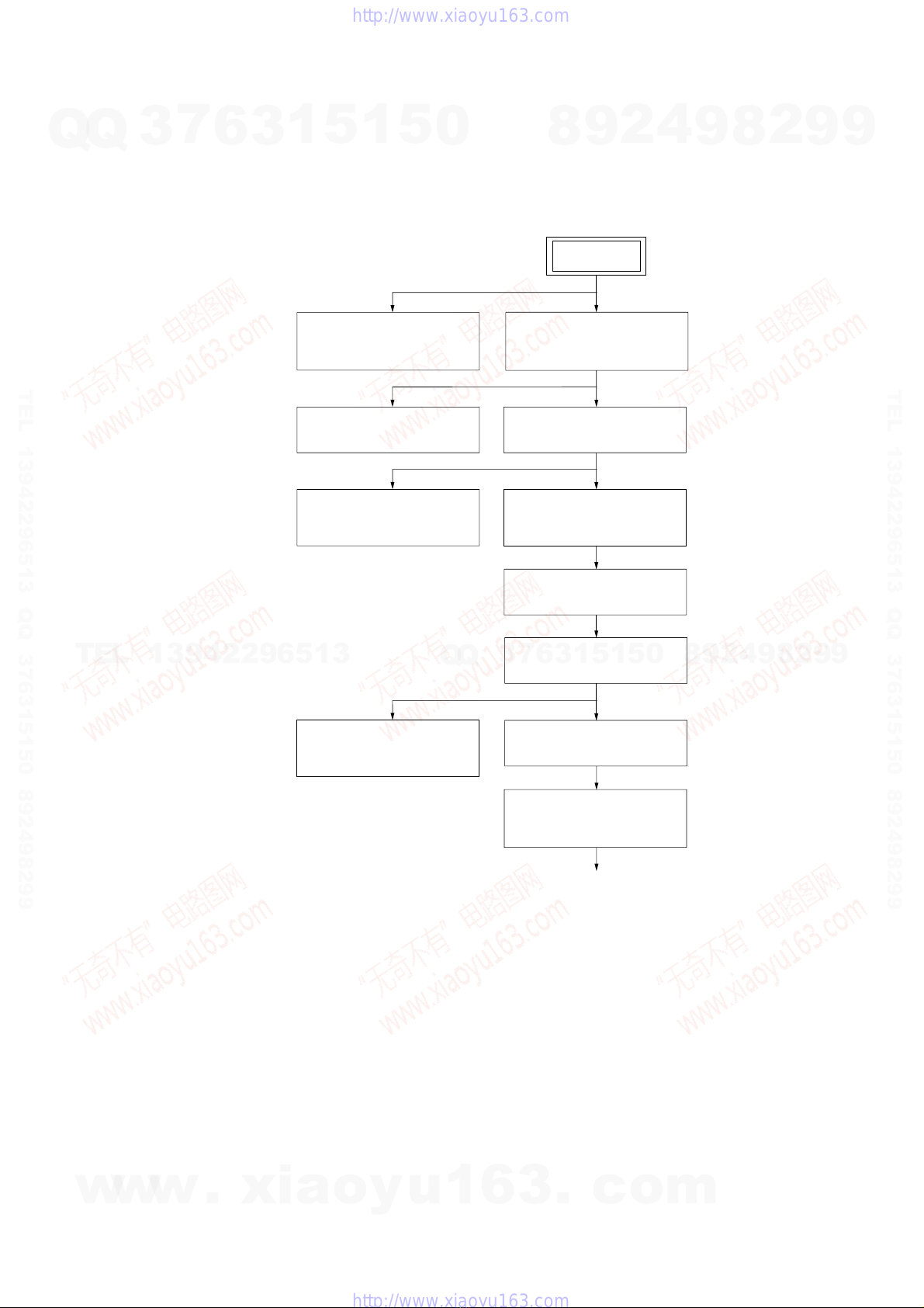
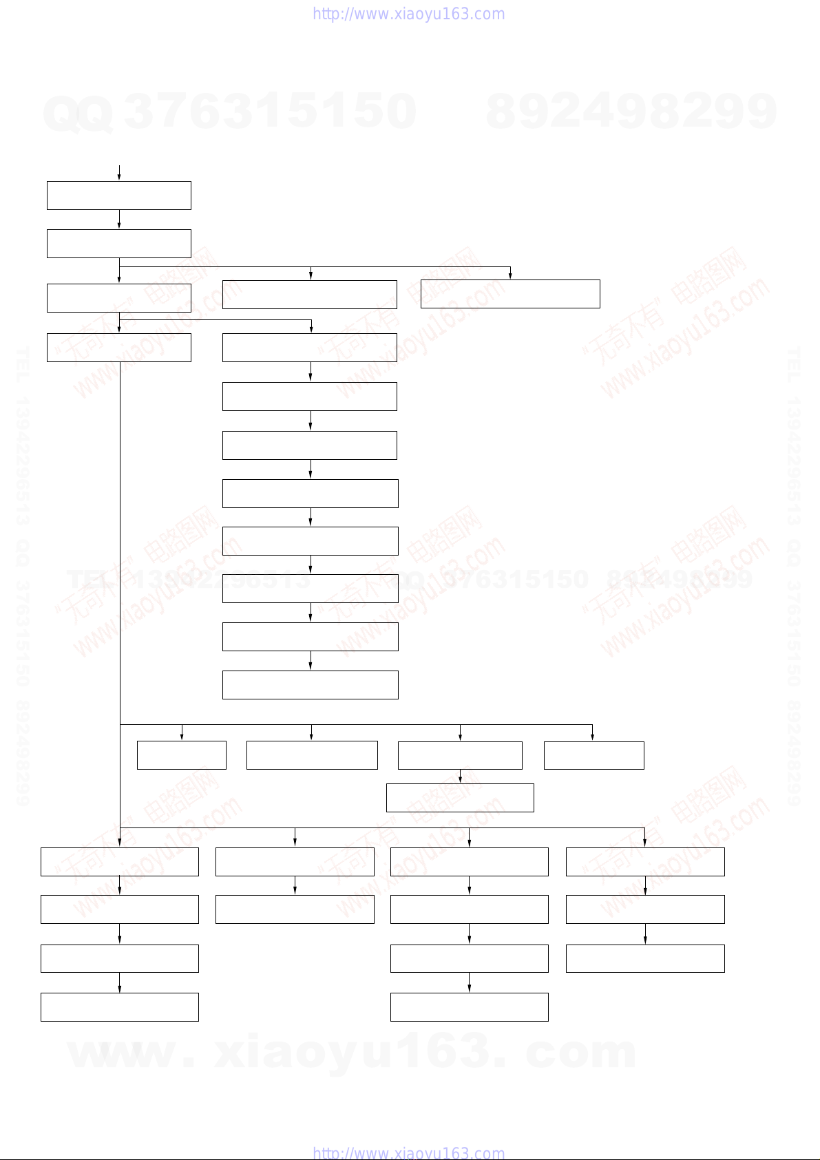
3-1. Disassembly Flow-1 ........................................................ 7
3-2. Disassembly Flow-2 ........................................................ 8
3-3. Optical Pick-Up Block .................................................... 9
3-4. Side Plate (L) (R), Top Panel Section.............................. 10
3-5. Mechanical Deck ............................................................. 11
3-6. Front Panel Section ......................................................... 12
3-7. PANEL (1), (2) Board, HEADPHONE Board ................ 12
3-8. Tuner (FM/AM), Dc Fan ................................................. 13
3-9. MAIN Board.................................................................... 14
3-10. Rear Panel Section........................................................... 14
3-11. AMP Board, Switching Regulator................................... 15
3-12. POWER Board ................................................................ 15
3-13. CD Mechanism Deck (CDM82A)................................... 16
3-14. Plate (Cover Top)............................................................. 17
3-15. Top Section ...................................................................... 17
3-16. Arm Section..................................................................... 18
3-17. CD Mechanism Deck Section ......................................... 19
3-18. Sub Gear (2 Step), Sub SliderAssy................................. 20
3-19. Arm (R) ........................................................................... 21
3-20. Gear (Stock Planet) (Right) ............................................. 22
3-21. Lever (Sub Gear Back L) ................................................ 22
3-22. Arm (L)............................................................................ 23
3-23. Gear (Stock Rot Long) (Left) .......................................... 24
3-24. Gear (Stock Rot Short) (Right) ....................................... 24
3-25. Stocker (1)Assy To Stocker (5)Assy.............................. 25
3-26. SPR-E (Roller Slider Upper) (Top Section) .................... 26
3-27. Rubber Roller (Top Section) ........................................... 26
3-28. LOD Motor...................................................................... 27
3-29. Slider (Push-popup)......................................................... 27
3-30. Rotary Encoder................................................................ 28
3-31. Assembling of the Rotary Encoder ................................. 29
3-32. ELV Motor....................................................................... 30
3-33. Chassis (Top), Chassis (Bottom) ..................................... 31
3-34. Lever (Loading R, Loading L) ........................................ 32
3-35. Disc Stop Lever ............................................................... 33
3-36. DRIVER Board ............................................................... 33
3-37. CD Board (A) .................................................................. 34
3-38. Optical Pick-up (KSM-215DCP) .................................... 34
3-39. Base Unit Section ............................................................ 35
3-40. Lever (BU Lock) ............................................................. 35
3-41. Gear (IDL-B) ................................................................... 36
3-42. Gear (IDL-C) ................................................................... 36
3-43. SPR-E (Tako-Back) ......................................................... 37
3-44. Plate (Push) Assy ............................................................. 38
3-45. SPR-P (Lock) .................................................................. 39
4. ASSEMBLY
4-1. Assembly Flow ................................................................ 40
4-2. Assembling of the Stocker Section ................................. 41
4-3. Assembling of the Gear (Stock Rot Short) (Right) ......... 42
4-4. Assembling of the Gear (Stock Rot Long) (Left)............ 43
4-5. Confirming theAssembling of the Stocker Section ........ 44
4-6. Assembling of the Gear (Stock Rotary Left)................... 45
4-7. Assembling of the Gear (Stock Rotary Right) ................ 46
4-8. Assembling of the Lever (Sub Gear Back L) .................. 47
4-9. Assembling of the Gear (Sub Gear Pin Right) ................ 48
4-10. Assembling of the Lever (Sub Gear Back R) .................. 49
4-11. Assembling of the Sub Gear (Idler) ................................ 50
4-12. Assembling of the Sub Gear (2 Step) .............................. 51
4-13. Confirming the Assembling of the Arm Section ............. 52
5. TEST MODE ............................................................... 53
6. ELECTRICAL ADJUSTMENTS .......................... 55
7. DIAGRAMS
7-1. Block Diagrams – CD Servo Section – ........................... 59
7-2. Block Diagrams – MAIN Section – ................................ 60
7-3. Block Diagrams
– PANEL/POWER SUPPLY Section – ........................... 61
7-4. Printed Wiring Board – CD Board – ............................... 62
7-5. Schematic Diagram – CD Board – .................................. 63
7-6. Printed Wiring Board – CD MECHANISM Section –.... 64
7-7. Schematic Diagram – CD MECHANISM Section – ...... 65
7-8. Printed Wiring Board – MAIN Board – .......................... 66
7-9. Schematic Diagram – MAIN Board (1/3) – .................... 67
7-10. Schematic Diagram – MAIN Board (2/3) – .................... 68
7-11. Schematic Diagram – MAIN Board (3/3) – .................... 69
7-12. Printed Wiring Board – AMP Board – ............................ 70
7-13. Schematic Diagram –AMP Board – ............................... 71
7-14. Printed Wiring Board – PANEL Section – ...................... 72
7-15. Schematic Diagram – PANEL Section – ......................... 73
7-16. Printed Wiring Board – POWER Board – ....................... 74
7-17. Schematic Diagram – POWER Board –.......................... 75
8. EXPLODED VIEWS
8-1. Side Plate, Top Panel Section .......................................... 83
8-2. Front Panel Section ......................................................... 84
8-3. Chassis Section................................................................ 85
8-4. CD Mechanism Deck Section-1 (CDM82A) .................. 86
8-5. CD Mechanism Deck Section-2 (CDM82A) .................. 87
8-6. CD Mechanism Deck Section-3 (CDM82A) .................. 88
8-7. CD Mechanism Deck Section-4 (CDM82A) .................. 89
8-8. CD Mechanism Deck Section-5 (CDM82A) .................. 90
8-9. CD Mechanism Deck Section-6 (CDM82A) .................. 91
8-10. CD Mechanism Deck Section-7 (CDM82A) .................. 92
8-11. CD Mechanism Deck Section-8 (CDM82A) .................. 93
8-12. CD Mechanism Deck Section-9 (CDM82A) .................. 94
8-13. CD Mechanism Deck Section-10 (CDM82A) ................ 95
8-14. Base Unit Section (BU-F1BD81A) ................................. 96
9. ELECTRICAL PARTS LIST .................................. 97
w
w
w
.
x
i
a
o
y
u
1
6
3
.
c
o
m
Q
Q
3
7
6
3
1
5
1
5
0
9
9
2
8
9
4
2
9
8
T
E
L
1
3
9
4
2
2
9
6
5
1
3
9
9
2
8
9
4
2
9
8
0
5
1
5
1
3
6
7
3
Q
Q
TEL 13942296513 QQ 376315150 892498299
http://www.xiaoyu163.com

3
HCD-HPX9
SAFETY CHECK-OUT
After correcting the original service problem, perform the following
safety check before releasing the set to the customer:
Check the antenna terminals, metal trim, “metallized” knobs, screws,
and all other exposed metal parts forAC leakage.
Check leakage as described below.
LEAKAGE TEST
The AC leakage from any exposed metal part to earth ground and
from all exposed metal parts to any exposed metal part having a
return to chassis, must not exceed 0.5 mA (500 microamperes.).
Leakage current can be measured by any one of three methods.
1. Acommercial leakage tester,suchas the Simpson 229 orRCA
WT-540A. Follow the manufacturers’instructions to use these
instruments.
2. A battery-operatedAC milliammeter. The Data Precision 245
digital multimeter is suitable for this job.
3. Measuring the voltage drop across a resistor by means of a
VOM or battery-operatedAC voltmeter.The “limit”indication
is 0.75V, so analog meters must have an accurate low-voltage
scale. The Simpson 250 and Sanwa SH-63Trd are examples
of a passive VOM that is suitable. Nearly all battery operated
digital multimeters that have a 2VAC range are suitable. (See
Fig. A)
Fig. A. Using an AC voltmeter to check AC leakage.
1.5 k
Ω
0.15
µ
FAC
voltmete
r
(0.75 V)
To Exposed Metal
Parts on Set
Earth Ground
Notes on chip component replacement
•Never reuse a disconnected chip component.
•Notice that the minus side of a tantalum capacitor may be
damaged by heat.
Flexible Circuit Board Repairing
•Keep the temperature of the soldering iron around 270 °C
during repairing.
•Do not touch the soldering iron on the same conductor of the
circuit board (within 3 times).
•Be careful not to apply force on the conductor when soldering
or unsoldering.
CAUTION
Use of controls or adjustments or performance of procedures
otherthan thosespecifiedherein may resultin hazardousradiation
exposure.
UNLEADED SOLDER
Boards requiring use of unleaded solder are printed with the lead-
free mark (LF) indicating the solder contains no lead.
(Caution: Some printed circuit boards may not come printed with
the lead free mark due to their particular size)
: LEAD FREE MARK
Unleaded solder has the following characteristics.
•Unleaded solder melts at a temperature about 40 °C higher
than ordinary solder.
Ordinary soldering irons can be used but the iron tip has to be
applied to the solder joint for a slightly longer time.
Soldering irons using a temperature regulator should be set to
about 350 °C.
Caution: The printed pattern (copper foil) may peel away if
the heated tip is applied for too long, so be careful!
•Strong viscosity
Unleaded solder is more viscou-s (sticky, less prone to flow)
than ordinary solder so use caution not to let solder bridges
occur such as on IC pins, etc.
•Usable with ordinary solder
It is best to use only unleaded solder but unleaded solder may
also be added to ordinary solder.
This appliance is
classified as a CLASS 1
LASER product. This
label is located on the
rear exterior.
SAFETY-RELATED COMPONENT WARNING!!
COMPONENTS IDENTIFIED BY MARK 0OR DOTTED LINE
WITH MARK 0ON THE SCHEMATIC DIAGRAMS AND IN
THE PARTS LIST ARE CRITICAL TO SAFE OPERATION.
REPLACE THESE COMPONENTS WITH SONY PARTS WHOSE
PART NUMBERS APPEAR AS SHOWN IN THIS MANUAL OR
IN SUPPLEMENTS PUBLISHED BY SONY.
ATTENTION AU COMPOSANT AYANT RAPPORT
À LA SÉCURITÉ!
LES COMPOSANTS IDENTIFIÉS PAR UNE MARQUE 0SUR
LES DIAGRAMMES SCHÉMATIQUES ET LA LISTE DES
PIÈCES SONT CRITIQUES POUR LA SÉCURITÉ DE
FONCTIONNEMENT. NE REMPLACER CES COM- POSANTS
QUE PAR DES PIÈCES SONY DONT LES NUMÉROS SONT
DONNÉS DANS CE MANUEL OU DANS LES SUPPLÉMENTS
PUBLIÉS PAR SONY.
w
w
w
.
x
i
a
o
y
u
1
6
3
.
c
o
m
Q
Q
3
7
6
3
1
5
1
5
0
9
9
2
8
9
4
2
9
8
T
E
L
1
3
9
4
2
2
9
6
5
1
3
9
9
2
8
9
4
2
9
8
0
5
1
5
1
3
6
7
3
Q
Q
TEL 13942296513 QQ 376315150 892498299
http://www.xiaoyu163.com

4
HCD-HPX9 SECTION 1
SERVICING NOTES
NOTES ON HANDLING THE OPTICAL PICK-UP
BLOCK OR BASE UNIT
The laser diode in the optical pick-up block may suffer electrostatic
break-down because of the potential difference generated by the
charged electrostatic load, etc. on clothing and the human body.
During repair, pay attention to electrostatic break-down and also
use the procedure in the printed matter which is included in the
repair parts.
The flexible board is easily damaged and should be handled with
care.
NOTES ON LASER DIODE EMISSION CHECK
The laser beam on this model is concentrated so as to be focused on
the disc reflective surface by the objective lens in the optical pick-
up block. Therefore, when checking the laser diode emission,
observe from more than 30 cm away from the objective lens.
LASER DIODE AND FOCUS SEARCH OPERATION
CHECK
Carry out the“S curve check”in “CD sectionadjustment” and check
that the S curve waveforms is output three times.
•MODEL IDENTIFICATION
– RearView –
Power requirement
indication
Model Name Power Voltage Indication
US, Canadian models AC: 120V -60 Hz
Saudi Arabia model AC: 120 – 127 V/220 or
230 – 240 V -50/60 Hz
Other models AC: 120 V, 220 V, 230 – 240 V
-50/60 Hz
Argentine model AC: 220 V -50 Hz
Australian model AC: 230 – 240V -50/60 Hz
w
w
w
.
x
i
a
o
y
u
1
6
3
.
c
o
m
Q
Q
3
7
6
3
1
5
1
5
0
9
9
2
8
9
4
2
9
8
T
E
L
1
3
9
4
2
2
9
6
5
1
3
9
9
2
8
9
4
2
9
8
0
5
1
5
1
3
6
7
3
Q
Q
TEL 13942296513 QQ 376315150 892498299
http://www.xiaoyu163.com

5
HCD-HPX9
SECTION 2
GENRAL This section is extracted
from instruction manual.
•LOCATION OF CONTROLS
Main unit
ALBUM +/– ws (11, 13)
Cassette compartment 4
CD SYNC qg (18)
DISC 1 – 5, +1 wf (11, 13)
DISC SKIP 5(11, 13)
Disc tray qs (10)
Display window 3
DSGX 6(19)
EX-CHANGE w; (10)
FM MODE qh (16, 27)
FUNCTION 9(11, 13, 15, 17,
23)
PHONES jack qk
PLAY MODE qj (11, 13, 18)
Remote sensor 2
REPEAT qh (12)
TUNER/BAND 0(14, 15)
TUNING +/– 8(14, 15)
TUNING MODE qj (14, 15)
VOLUME 7(20, 26)
?/1 (power) 1(8, 15, 20, 21,
28)
.m/M> (skip back/
skip forward, rewind/fast
forward) 8(11, 13)
xwd (11, 15, 28)
XTAPE (pause) qd (17)
zREC qf (18)
CD/NX (play/pause) ql (11,
13, 27)
TAPE/N(play) wa (17)
Z(CD eject) qa (10, 11)
ALPHABETICAL ORDER
A – O P – Z
BUTTON DESCRIPTIONS
+/1
HS
xlj JL
zX
A
12 34
5
6
9
0
7
8
qa
wa
ws
wd
wf
w;
ql
qs
qdqhqjqk qgqf
w
w
w
.
x
i
a
o
y
u
1
6
3
.
c
o
m
Q
Q
3
7
6
3
1
5
1
5
0
9
9
2
8
9
4
2
9
8
T
E
L
1
3
9
4
2
2
9
6
5
1
3
9
9
2
8
9
4
2
9
8
0
5
1
5
1
3
6
7
3
Q
Q
TEL 13942296513 QQ 376315150 892498299
http://www.xiaoyu163.com

6
HCD-HPX9
Remote control
ALBUM +/– qs (11, 13)
CD qj (11, 13, 15)
CLEAR qf (13)
CLOCK/TIMER SELECT 2
(20, 21, 26)
CLOCK/TIMER SET 3(9, 20,
21)
DISC SKIP 0(11, 13)
DISPLAY w; (16, 22)
ENTER 9(9, 13, 20, 21)
EQ qd (19)
FM MODE 4(16, 27)
FUNCTION 6(11, 13, 15, 17,
23)
ALPHABETICAL ORDER
A – O
PLAY MODE ql (11, 13, 18)
REPEAT 4(12)
SLEEP wa (19)
TAPE qh (17)
TUNER/BAND 5(14, 15)
TUNER MEMORY qk (14)
TUNING MODE ql (14, 15)
VOLUME +/– qa (20, 26)
P – Z ?/1 (power) 1(8, 15, 20, 21,
28)
m/M (rewind/fast forward)
7(11, 17)
./> (skip back/skip
forward) qg (9, 11, 13, 19, 20,
21)
x(stop) 8(11, 15, 17, 18, 28)
X(pause) 8(11, 17)
N(play) 8(11, 13, 17, 27)
+/– (tuning) qg (14, 15)
BUTTON DESCRIPTIONS
4
5
6
7
8
9
wa 1
qs
qf
qd
w;
ql
qk
qj
qh
qg
qa
0
3
2
Use buttons on the remote for the operation.
1Press ?/1 to turn on the system.
2Press CLOCK/TIMER SET.
3Press ./> repeatedly to set the
hour.
4Press ENTER.
5Press ./> repeatedly to set the
minute.
6Press ENTER.
The clock starts working.
To adjust the clock
1Press CLOCK/TIMER SET.
2Press ./> until “CLOCK SET”
appears, then press ENTER.
3Do the same procedures as step 3 to 6
above.
Note
The clock is not displayed in Power Saving Mode
Setting the clock
w
w
w
.
x
i
a
o
y
u
1
6
3
.
c
o
m
Q
Q
3
7
6
3
1
5
1
5
0
9
9
2
8
9
4
2
9
8
T
E
L
1
3
9
4
2
2
9
6
5
1
3
9
9
2
8
9
4
2
9
8
0
5
1
5
1
3
6
7
3
Q
Q
TEL 13942296513 QQ 376315150 892498299
http://www.xiaoyu163.com

7
HCD-HPX9
SECTION 3
DISASSEMBLY
•This is can be disassemble according to the following sequence.
3-6.FRONT PANEL SECTION
(Page 12)
3-8.TUNER (FM/AM),
DC FAN
(Page 13)
3-9.MAIN BOARD
(Page 14)
3-10.REAR PANEL SECTION
(Page 14)
3-5.MECHANICAL DECK
(Page 11)
3-3.OPTICAL PICK-UP
BLOCK
(Page 9)
3-11.AMP BOARD,
SWITCHING REGULATOR
(Page 15)
3-12.POWER BOARD
(Page 15)
to DISASSEMBLY FLOW-2
3-13.CD MECHANISM DECK
(CDM82A)
(Page 16)
3-7.PANEL (1), (2) BOARD
HEADPHONE BOARD
(Page 12)
3-4.SIDE PLATE (L) (R),
TOP PANEL SECTION
(Page 10)
SET
3-1. DISASSEMBLY FLOW-1
w
w
w
.
x
i
a
o
y
u
1
6
3
.
c
o
m
Q
Q
3
7
6
3
1
5
1
5
0
9
9
2
8
9
4
2
9
8
T
E
L
1
3
9
4
2
2
9
6
5
1
3
9
9
2
8
9
4
2
9
8
0
5
1
5
1
3
6
7
3
Q
Q
TEL 13942296513 QQ 376315150 892498299
http://www.xiaoyu163.com

8
HCD-HPX9
3-25. STOCKER (1) ASSYTO
STOCKER (5) ASSY (Page 25)
3-14. PLATE (COVER TOP)
(Page 17)
3-15.TOP SECTION
(Page 17)
3-16. ARM SECTION
(Page 18)
3-18. SUB GEAR (2 STEP),
SUB SLIDER ASSY (Page 20)
3-19. ARM (R)
(Page 21)
3-20. GEAR (STOCK PLANET)
(RIGHT) (Page 22)
3-21. LEVER (SUB GEAR BACK L)
(Page 22)
3-22. ARM (L)
(Page 23)
3-23. GEAR (STOCK ROT LONG)
(LEFT) (Page 24)
3-24. GEAR (STOCK ROT SHORT)
(RIGHT) (Page 24)
3-26.SPR-E (ROLLER SLIDER UPPER)
(TOP SECTION) (Page 26)
3-29.SLIDER (PUSH-POPUP)
(Page 27)
3-28. LOD MOTOR
(Page 27)
3-17. CD MECHANISM DECK
SECTION (Page 19)
from DISASSEMBLY FLOW-1
3-30. ROTARY ENCODER
(Page 28) 3-32. ELV MOTOR
(Page 30)
3-31.ASSEMBLING OF THE
ROTARY ENCODER (Page 29)
3-27. RUBBER ROLLER
(TOP SECTION) (Page 26)
3-33. CHASSIS (TOP),
CHASSIS (BOTTOM) (Page 31)
3-34.LEVER
(LOADING R, LOADING L) (Page 32)
3-35. DISC STOP LEVER
(Page 33)
3-36. DRIVER BOARD
(Page 33)
3-37. CD BOARD (A)
(Page 34) 3-39. BASE UNIT SECTION
(Page 35)
3-38. OPTICAL PICK-UP
(KSM-215DCP) (Page 34) 3-40. LEVER (BU LOCK)
(Page 35)
3-41. GEAR (IDL-B)
(Page 36)
3-42. GEAR (IDL-C)
(Page 36)
3-43. SPR-E (TAKO-BACK)
(Page 37)
3-44. PLATE (PUSH) ASSY
(Page 38)
3-45. SPR-P (LOCK)
(Page 39)
3-2. DISASSEMBLY FLOW-2
w
w
w
.
x
i
a
o
y
u
1
6
3
.
c
o
m
Q
Q
3
7
6
3
1
5
1
5
0
9
9
2
8
9
4
2
9
8
T
E
L
1
3
9
4
2
2
9
6
5
1
3
9
9
2
8
9
4
2
9
8
0
5
1
5
1
3
6
7
3
Q
Q
TEL 13942296513 QQ 376315150 892498299
http://www.xiaoyu163.com

9
HCD-HPX9
1
two screws
(BVTT3
×
6
)
qs
flotaing screw
(+PTPWH M2.6)
0
flotaing screw
(+PTPWH M2.6)
4
screw
(BTTP M2.6)
7
screw
(BTTP M2.6)
2
bottom cover plate
qk
optical pick-up bloc
k
qd
insulator spring (coil)
qa
insulator spring (coil)
6
insulator spring (coil)
9
insulator spring (coil)
5
BU stopper
8
BU stopper
qh
insulator
qj
insulator
qf
insulator
qg
insulator
3
w
ire (flat type)
27p(CN201)
Note: Follow the disassembly procedure in the numerical order given.
3-3. OPTICAL PICK-UP BLOCK
w
w
w
.
x
i
a
o
y
u
1
6
3
.
c
o
m
Q
Q
3
7
6
3
1
5
1
5
0
9
9
2
8
9
4
2
9
8
T
E
L
1
3
9
4
2
2
9
6
5
1
3
9
9
2
8
9
4
2
9
8
0
5
1
5
1
3
6
7
3
Q
Q
TEL 13942296513 QQ 376315150 892498299
http://www.xiaoyu163.com

10
HCD-HPX9
2
two screws
(BVTT3
×
6
)
1
two screws
(BVTP3
×
10
)
8
two screws
(BVTP3
×
8
)
5
two screws
(BVTP3
×
10
)
6
two screws
(BVTP3
×
6
)
4
side plate (R) assy
3
shield cover
When you exchange Side plate (R) assy,
please remove Shield cover from old Side plate (R),
and attach in new Side plate (R).
7
side plate (L)
qs
top panel section
0
connector
(CN301)
9
w
ire (flat type)
7p(CN317)
qa
screw
(BVTP3
×
6
)
3-4. SIDE PLATE (L) (R), TOP PANEL SECTION
w
w
w
.
x
i
a
o
y
u
1
6
3
.
c
o
m
Q
Q
3
7
6
3
1
5
1
5
0
9
9
2
8
9
4
2
9
8
T
E
L
1
3
9
4
2
2
9
6
5
1
3
9
9
2
8
9
4
2
9
8
0
5
1
5
1
3
6
7
3
Q
Q
TEL 13942296513 QQ 376315150 892498299
http://www.xiaoyu163.com

11
HCD-HPX9
3-5. MECHANICAL DECK
5
two screws
(BVTP2.6
×
8
)
1
three screws
(BVTP2.6
×
8
)
6
two screws
(BVTP2.6
×
8
)
2
three screws
(BVTP2.6
×
8
)
8
mechanical deck
earth wire
qa
cassette panel
9
leaf spring (cassette
)
4
cassette door
0
leaf spring (cassette)
7
cassette shield plate
3
top panel
w
w
w
.
x
i
a
o
y
u
1
6
3
.
c
o
m
Q
Q
3
7
6
3
1
5
1
5
0
9
9
2
8
9
4
2
9
8
T
E
L
1
3
9
4
2
2
9
6
5
1
3
9
9
2
8
9
4
2
9
8
0
5
1
5
1
3
6
7
3
Q
Q
TEL 13942296513 QQ 376315150 892498299
http://www.xiaoyu163.com

12
HCD-HPX9
1
screw
(KTP3
×
8
)
4
two screws
(BVTT3
×
6
)
2
screw
(KTP3
×
8
)
5
screw
(BVTP3
×
6
)
3
CD panel
8
front panel section
7
connector
(CN604)
6
w
ire (flat type) 17p(CN310)
3-6. FRONT PANEL SECTION
qd
four screws
(BVTP2.6
×
8
)
4
five screws
(BVTP2.6
×
8
)
5
seven screws
(BVTP2.6
×
8
)
9
screw
(PWH2.6
×
10
)
7
connector
(CN802)
qa
connector
(CN312)
0
connector
(CN311)
6
w
ire (flat type)
17p(CN801)
8
PANEL (1) board
qs
HEADPHONE board
qf
PANEL (2) board
qg
claw
1
knob
(volume)
2
nut
3
washer
3-7. PANEL (1), (2) BOARD, HEADPHONE BOARD
w
w
w
.
x
i
a
o
y
u
1
6
3
.
c
o
m
Q
Q
3
7
6
3
1
5
1
5
0
9
9
2
8
9
4
2
9
8
T
E
L
1
3
9
4
2
2
9
6
5
1
3
9
9
2
8
9
4
2
9
8
0
5
1
5
1
3
6
7
3
Q
Q
TEL 13942296513 QQ 376315150 892498299
http://www.xiaoyu163.com

13
HCD-HPX9
3-8. TUNER (FM/AM), DC FAN
qf
two screws (FAN)
1
two screws
(BVTP3
×
8
)
2
screw
(BVTP3
×
8
)
3
two screws
(BVTP3
×
8
)
4
three screws
(BVTP3
×
8
)
0
two screws
(BVTP3
×
10
)
8
connector
(CN313)
6
claw
qg
DC fan
qa
tuner (FM/AM)
qd
heat cover plate
5
claw
9
w
ire (flat type) 11p(CN305)
qs
w
ire (flat type) 11p
7
heat sink cover
heat sink cover
MAIN board
w
w
w
.
x
i
a
o
y
u
1
6
3
.
c
o
m
Q
Q
3
7
6
3
1
5
1
5
0
9
9
2
8
9
4
2
9
8
T
E
L
1
3
9
4
2
2
9
6
5
1
3
9
9
2
8
9
4
2
9
8
0
5
1
5
1
3
6
7
3
Q
Q
TEL 13942296513 QQ 376315150 892498299
http://www.xiaoyu163.com

14
HCD-HPX9
3-9. MAIN BOARD
4
connector
(CN309)
5
connector
(CN303)
6
connector
(CN308)
3
connector
(CN316)
2
connector
(CN307)
9
MAIN board
8
w
ire (flat type)
(27p)(CN304)
7
w
ire (flat type)
(21p)(CN315)
1
w
ire (flat type)
(9p)(CN306)
3-10. REAR PANEL SECTION
2
two screws
(BVTP3
×
16
)
1
two screws
(BVTP3
×
8)
3
three screws
(BVTP3
×
8
)
7
rear panel section
5
connector
(CN903)
6
connector
(CN602)
4
connector
(CN904)
w
w
w
.
x
i
a
o
y
u
1
6
3
.
c
o
m
Q
Q
3
7
6
3
1
5
1
5
0
9
9
2
8
9
4
2
9
8
T
E
L
1
3
9
4
2
2
9
6
5
1
3
9
9
2
8
9
4
2
9
8
0
5
1
5
1
3
6
7
3
Q
Q
TEL 13942296513 QQ 376315150 892498299
http://www.xiaoyu163.com

15
HCD-HPX9
3-12. POWER BOARD
3
two screws
(BVTP3
×
6
)
5
two screws
(BVTP3
×
12
)
6
main heat sink
8
two screws
(BVTP3
×
16
)
7
screw
(BVTP3
×
8
)
1
connector
(CN101)
2
connector
(CN201)
4
SWITCHING REGULATOR
9
AMP board
rear panel
3-11. AMP BOARD, SWITCHING REGULATOR
3
two screws
(BVTT4
×
6
)
4
two screws
(BVTT4
×
6
)
2
connector
(CN902)
1
connector
(CN901)
T901
5
POWER board
w
w
w
.
x
i
a
o
y
u
1
6
3
.
c
o
m
Q
Q
3
7
6
3
1
5
1
5
0
9
9
2
8
9
4
2
9
8
T
E
L
1
3
9
4
2
2
9
6
5
1
3
9
9
2
8
9
4
2
9
8
0
5
1
5
1
3
6
7
3
Q
Q
TEL 13942296513 QQ 376315150 892498299
http://www.xiaoyu163.com

16
HCD-HPX9
3-13. CD MECHANISM DECK (CDM82A)
9
four screws
(BVTT3
×
10
)
0
chassis
qs
ffc cover
qd
w
ire (flat type)
27p (CN201)
qa
w
ire (flat type)
21p (CN801)
qf
CD mechanism deck
(CDM82A)
1
two screws
(BVTT3
×
6
)
2
two screws
(BVTT3
×
6
)
6
screw
(BVTP2.6
×
8
)
7
screw
(BVTT3
×
6
)
4
screw
(BVTP2.6
×
8
)
8
plate
5
clamp
clamp
sub chassis
Please attach connector,
as shown in a figure.
connector
plate
3
sub chassis
w
w
w
.
x
i
a
o
y
u
1
6
3
.
c
o
m
Q
Q
3
7
6
3
1
5
1
5
0
9
9
2
8
9
4
2
9
8
T
E
L
1
3
9
4
2
2
9
6
5
1
3
9
9
2
8
9
4
2
9
8
0
5
1
5
1
3
6
7
3
Q
Q
TEL 13942296513 QQ 376315150 892498299
http://www.xiaoyu163.com

17
HCD-HPX9
3-14. PLATE (COVERTOP)
3
four screws
(BTTPM 2.6
×
8)
4
plate (cover top)
8
plate (cam R)
7
screw
(BTTPM 2.6
×
8)
6
plate (cam L)
5
screw
(BTTPM 2.6
×
8
)
1
gear (joint op)
2
gear (joint op), shaft (stock)
3-15. TOP SECTION
1
screw (BTP 2
×
8)
2
gear (connection tp)
4
two screws
(PTPWH 2
×
14)
shock guard
(lower)
6
shock guard
(lower)
5
claw
3
two screws
(BTP 2
×
8)
7
top section
8
shaft (connection)
w
w
w
.
x
i
a
o
y
u
1
6
3
.
c
o
m
Q
Q
3
7
6
3
1
5
1
5
0
9
9
2
8
9
4
2
9
8
T
E
L
1
3
9
4
2
2
9
6
5
1
3
9
9
2
8
9
4
2
9
8
0
5
1
5
1
3
6
7
3
Q
Q
TEL 13942296513 QQ 376315150 892498299
http://www.xiaoyu163.com

18
HCD-HPX9
3-16. ARM SECTION
B
A
1
T
urn over the
pulley (LOD motor)
in the direction of the arrow
A
.
2
Slide the arm section in the
direction of the arrow
B
.
4
Push this portion with a finger
in the direction of the arrow
C
.
3
claw
6
arm section
5
Remove the
arm section
in the direction of the arrow
D
.
C
D
1
gear (joint op),
two shaft (shaft) stocks
8
gear (joint op), two shaft (shaft) stocks
2
loosen two
screws
4
two claws
5
arm section
3
turn over the
gear (swing)
in the direction
of the arrow.
7
two
screws
6
Push this portion with a finger
in the direction of the arrow
C
.
gear (swing)
PRECAUTION DURING ARM SECTION
INSTALLATION
w
w
w
.
x
i
a
o
y
u
1
6
3
.
c
o
m
Q
Q
3
7
6
3
1
5
1
5
0
9
9
2
8
9
4
2
9
8
T
E
L
1
3
9
4
2
2
9
6
5
1
3
9
9
2
8
9
4
2
9
8
0
5
1
5
1
3
6
7
3
Q
Q
TEL 13942296513 QQ 376315150 892498299
http://www.xiaoyu163.com

19
HCD-HPX9
3-17. CD MECHANISM DECK SECTION
A
4
Remove the CD mechanism deck section
in the direction of the arrow
C
.
1
T
urn over the
pulley (ELV motor)
in the direction of the arrow
A
.
pulley (ELV motor)
3
four
claws
plate (cam L)
B
C
2
Slide the
CD mechanism deck section
in the direction of the arrow
B
.
w
w
w
.
x
i
a
o
y
u
1
6
3
.
c
o
m
Q
Q
3
7
6
3
1
5
1
5
0
9
9
2
8
9
4
2
9
8
T
E
L
1
3
9
4
2
2
9
6
5
1
3
9
9
2
8
9
4
2
9
8
0
5
1
5
1
3
6
7
3
Q
Q
TEL 13942296513 QQ 376315150 892498299
http://www.xiaoyu163.com

20
HCD-HPX9
3-18. SUB GEAR (2 STEP), SUB SLIDER ASSY
2
two screws (M2
×
5)
1
k tapping screw (K2.6
×
8)
3
cover (R)
4
sub gear (idler)
5
sub gear (2 step)
0
sub slider assy
9
Remove the
sub slider assy
in the direction of the arrow.
6
sub gear (idler)
7
sub gear (idler)
8
sub gear (idler)
sub slider assy
w
w
w
.
x
i
a
o
y
u
1
6
3
.
c
o
m
Q
Q
3
7
6
3
1
5
1
5
0
9
9
2
8
9
4
2
9
8
T
E
L
1
3
9
4
2
2
9
6
5
1
3
9
9
2
8
9
4
2
9
8
0
5
1
5
1
3
6
7
3
Q
Q
TEL 13942296513 QQ 376315150 892498299
http://www.xiaoyu163.com
Other manuals for HCD-HPX9 - Hi Fi Components
1
This manual suits for next models
1
Table of contents
Other Sony Stereo System manuals

Sony
Sony CHC-TB20 User manual

Sony
Sony SEN-311CD User manual

Sony
Sony HCD-GRX50 User manual

Sony
Sony HCD-NE3 User manual

Sony
Sony HCD-GNX660 Building instructions

Sony
Sony LBT-LX7 User manual

Sony
Sony HCD-LX7 User manual

Sony
Sony ZS-SAT1 User manual

Sony
Sony MHC-RV20 User manual

Sony
Sony LBT-N250 User manual

Sony
Sony 2-661-374-11(4) User manual

Sony
Sony SHAKE-99D User manual

Sony
Sony CMT-EP50 Setup guide

Sony
Sony HCD-GS200 User manual

Sony
Sony ICF-C11iP User manual

Sony
Sony PMC-DR50L User manual

Sony
Sony MHC-W550 User manual

Sony
Sony XDR-DS16iPN User manual

Sony
Sony GTK-XB72 User manual

Sony
Sony DHC-MD373 User manual