Sony HCD-VZ50MD User manual

HCD-VZ50MD
E Model
Tourist Model
SERVICE MANUAL
MINI Hi-Fi COMPONENT SYSTEM
— Continued on next page —
SPECIFICATIONS
HCD-VZ50MD is the tuner, deck, CD, MD and
amplifier section in DHC-VZ50MD.
This stereo system is equipped with the Dolby B-type
noise reduction system*.
* Manufactured under license from Dolby
Laboratories Licensing Corporation.
DOLBY and the double-D symbol ;are
trademarks of Dolby Laboratories Licensing
Corporation.
Model Name Using Similar Mechanism NEW
CD Mechanism Type CDM53F-K4BD37
Base Unit Type BU-K4BD37
Optical Pick-up Type KSM-213DHAP/Z-NP
Model Name Using Similar Mechanism HCD-ZX50MD
MD Mechanism Type MDM-7B
Optical Pick-up Type KMS-260B/J1N
Model Name Using Similar Mechanism HCD-ZX50MD
Tape Transport Mechanism Type TCM-230AWR12
CD
SECTION
MD
SECTION
TAPE DECK
SECTION
Amplifier section
The following measured at 120/220/240 V AC, 50/60 Hz
DIN power output (rated) 115 + 115 watts
(6 ohms at 1 kHz, DIN)
Continuous RMS power output (reference)
150 + 150 watts
(6 ohms at 1 kHz,
10 % THD)
Inputs
VIDEO (AUDIO) IN: voltage 250 mV,
(phono jacks) impedance 47 kilohms
MIC 1/2: sensitivity 1 mV,
(mini jack) impedance 10 kilohms
Outputs
VIDEO OUT: max. output level
(phono jack) 1 Vp-p, unbalanced,
Sync negative, load impedance
75 ohms
S-VIDEO OUT: Y: 1 Vp-p, unbalanced,
(4-pin/mini-DIN jack) Sync negative,
C: 0.286 Vp-p,
load impedance 75 ohms
PHONES: accepts headphones of
(stereo mini jack) 8 ohms or more
FRONT SPEAKER: accepts impedance of 6 to 16 ohms
SUPER WOOFER: Voltage 1 V, impedance 1 kilohms
VIDEO CD/CD player section
System Compact disc and digital audio
system
Laser Semiconductor laser
(λ=780 nm)
Emission duration: continuous
Laser output Max. 44.6 µW*
*This output is the value measured
at a distance of 200 mm from the
objective lens surface on the
Optical Pick-up Block with 7 mm
aperture.
Wavelength 780 – 790 nm
Frequency response 2 Hz – 20 kHz (±0.5 dB)
Signal-to-noise ratio More than 90 dB
Dynamic range More than 90 dB
Video color system format NTSC, PAL
MD deck section
System MiniDisc digital audio system
Laser Semiconductor laser (λ=780 nm)
Emission duration: continuous
Laser output Max. 44.6 µW*
*This output is the value measured
at a distance of 200 mm from the
objective lens surface on the
Optical Pick-up Block with a
7 mm aperture.
Sampling frequency 44.1 kHz
Frequency response 20 –20,000 Hz
Tape player section
Recording system 4-track 2-channel stereo
Frequency response 40 –13,000 Hz (±3 dB),
(DOLBY NR OFF) using Sony TYPE I cassette
40 –14,000 Hz (±3 dB),
using Sony TYPE II cassette

2
Procedure for using the Self-Diagnosis Function (Error History Display Mode).
Note: Perform the self-diagnosis function in the “error history display mode”in the test mode. The following describes the least required
procedure. Be careful not to enter other modes by mistake. If other modes are entered accidentally, press the NAME EDIT/
CHARACTER button while REC IT is lit, and when REC IT goes off, press the MD Zbutton to exit the mode.
1. In the power ON state, set the function to MD, and while pressing the DISPLAY and xbuttons together, press V-GROOVE . While
the test mode is set. “[Check]”will be displayed.
2. Move the multi-stick left and right to display “[Service]”and press the PUSH ENTER button.
3. Move the multi-stick left and right to display “Err Display”.
4. Press the PUSH ENTER button to enter the error history mode. “op rec tm”will be displayed.
5. Select the item to be displayed or executed using the multi-stick.
6. Press the NAME EDIT/CHARACTER button so that REC IT lights up.
7. Press the MD REC MODE button to display the selected item.
8. Press the REC MODE button another time to return to step 4.
9. Pressing the CLEAR button when REC IT is lit displays “Err Display”and exits the error history display mode.
10. To exit the test mode, press the MD Zbutton while REC IT is off. This sets the standby state and ends the test mode.
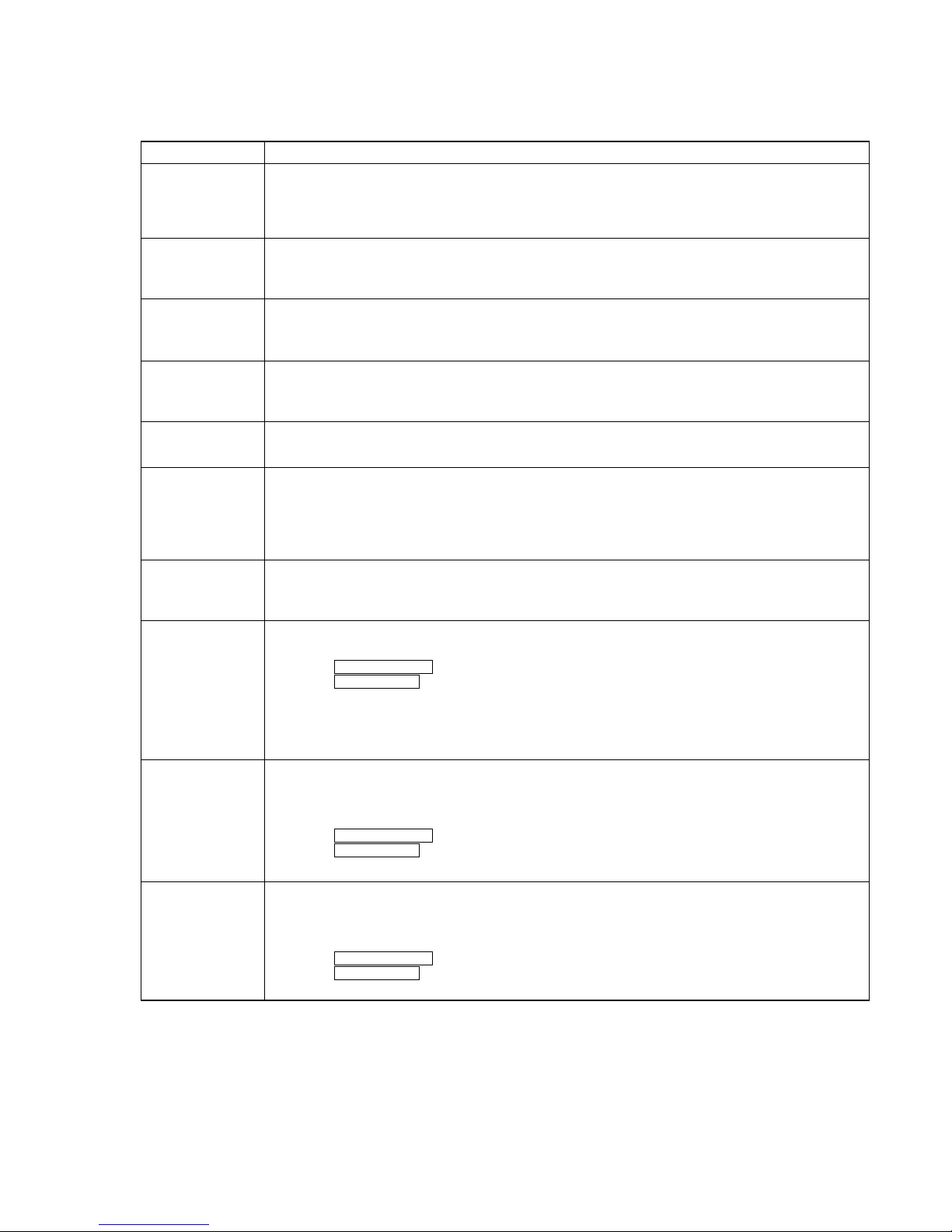
Self-diagnosis Display
This system has the Self-diagnosis display
function to let you know if there is a system
malfunction. The display shows a code made up of
three or five letters and a message alternately to
show you the problem. To solve the problem, refer
to the following list. If any problem persists,
consult your nearest Sony dealer.
C11 / Protected
The MD is protected against erasure.
pRemove the MD and slide the tab to close the
slot (page 49).
C12 / Cannot Copy
You are attempting to record a CD with a
format that the system does not support, such as
CD-ROM.
p––
C13 / REC Error
Recording is not possible.
pMove the system to a stable place and start
recording over from the beginning.
The MD is dirty or is scratched or the MD does
not meet the standards.
pChange the MD with another one and start
recording over from the beginning.
C13 / Read Error
The MD cannot read the disc information
correctly.
pEject the MD once, then insert it again.
C14 / Toc Error
The MD cannot read the disc information
correctly.
pChange the MD with another one.
pErase all the recorded contents of the MD
using the Erase function.
C41 / Cannot Copy
This unit complies with the Serial Copy
Management System (SCMS) which limits the
number of digital copies that can be made of
any given digital audio source.
E0001 / MEMORY NG
The component has internal problems.
pConsult your nearest Sony dealer.
E0101 / LASER NG
There is a problem with the laser pickup.
pThe laser pickup may be damaged. Consult
your nearest Sony dealer.
Tuner section
FM stereo, FM/AM superheterodyne tuner
FM tuner section
Tuning range
Tourist model: 76.0 –108.0 MHz
Other models: 87.5 –108.0 MHz
Antenna FM lead antenna
Antenna terminals 75 ohm unbalanced
Intermediate frequency 10.7 MHz
AM tuner section
Tuning range 531 –1,602 kHz
(with the interval set at
9 kHz)
530 –1,710 kHz
(with the interval set at
10 kHz)
Antenna AM loop antenna
Antenna terminals External antenna terminal
Intermediate frequency 450 kHz
General
Power requirements 120 V, 220 V, 230 –240 V AC,
50/60 Hz
Adjustable with voltage selector
Power consumption 180 watts
Dimensions (w/h/d) Approx. 250 x 375 x 395 mm
Mass Approx. 12.0 kg
Supplied accessories: AM loop antenna (1)
FM lead antenna (1)
Remote Commander (1)
Batteries (2)
Video cable (1)
Speaker cords (2)
Front speaker pads (8)
Design and specifications are subject to change
without notice.

3
ITEMS OF ERROR HISTORY MODE ITEMS AND CONTENTS
Selecting the Test Mode
Display
op rec tm
op play tm
spdl rp tm
retry err
total err
err history
retry adrs
er refresh
op change
spdl change
History
Displays the total recording time.
When the total recording time is more than 1 minute, displays the hour and minute
When less than 1 minute, displays “Under 1 min”
The display time is the time the laser is set to high power, which is about 1/4 of the actual recording time.
Displays the total playback time.
When the total playback time is more than 1 minute, displays the hour and minute
When less than 1 minute, displays “Under 1 min”
Displays the total rotating time of the spindle motor.
When the total rotating time is more than 1 minute, displays the hour and minute
When less than 1 minute, displays “Under 1 min”
Displays the total number of retry errors during recording and playback
Displays “r xx p yy”. xx is the number of errors during recording. yy is the number of errors during playback.
This is displayed in hexadecimal from 00 to FF.
Displays the total number of errors
Displays “total xx”. This is displayed in hexadecimal from 00 to FF.
Displays the past ten errors.
Displays “0x ErrCd@@”.
X is the history number. The younger the number, the more recent is the history (00 is the latest). @@ is the
error code.
Select the error history number using the Multi stick.
Displays the past five retry addresses.
Displays “xx ADRS yyyy”, xx is the history number, yyyy is the cluster with the retry error.
Select the error history number using the Multi stick.
Mode for erasing the error and retry address histories
Procedure
1. Press the MD REC MODE button while “REC IT”is lit when displayed as “er refresh”.
2. Press the PUSH ENTER button when the display changes to “er refresh?”.
When “Complete!!”is displayed, it means erasure has completed.
Be sure to check the following after executing this mode.
*Data has been erased.
*Perform recording and playback, and check that the mechanism is normal.
Mode for erasing the total time of op rec tm, op play tm.
These histories are based on the time of replacement of the optical pick-up. If the optical pick-up has been
replaced, perform this procedure and erase the history.
Procedure
1. Press the MD REC MODE button while “REC IT”is lit when displayed as “op change”.
2. Press the PUSH ENTER button when the display changes to “op change?”.
When “Complete!!”is displayed, it means erasure has completed.
Mode for erasing the total spdl rp tm time
These histories are based on the time of replacement of the spindle motor. If the spindle motor has been
replaced, perform this procedure and erase the history.
Procedure
1. Press the MD REC MODE button while “REC IT”is lit when displayed as “spdl change”
2. Press the PUSH ENTER button when the display changes to “spdl change?”
When “Complete!!”is displayed, it means erasure has completed.

4
Description
Table of Error Codes
Error Code
10
12
20
21
22
23
24
30
31
40
41
42
43
50
51
Could not load
Loading switches combined incorrectly
Timed out without reading the top of PTOC
Could read top of PTOC, but detected error
Timed out without accessing UTOC
Timed out without reading UTOC
Error in UTOC
Could not start playback
Error in sector
Retry cause generated during normal recording
Retried in DRAM overflow
Retry occurred during TOC writing
Retry aborted during S.F editing
Other than access processing, and could not read address.
Focus NG occurred and overran.

5
TABLE OF CONTENTS
MODEL IDENTIFICATION
—BACK PANEL —
•Abbreviation
HK : Hong Kong model
MY : Malaysia model
SP : Singapore model
JE : Tourist model
MODEL
SP, MY model
HK model
JE model
PARTS No.
4-227-557-0s
4-227-557-1s
4-227-557-2s
1. SERVICING NOTES ···················································6
2. GENERAL ........................................................................ 14
3. DISASSEMBLY ································································ 17
4. TEST MODE ...................................................................... 25
5. MECHANICAL ADJUSTMENTS ............................... 33
6. ELECTRICAL ADJUSTMENTS................................. 33
7. DIAGRAMS ······································································· 48
7-1. Circuit Boards Location ·············································· 48
7-2. Block Diagrams ··························································· 51
7-3. Printed Wiring Board –Deck Section – ······················ 56
7-4. Schematic Diagram –Deck Section – ························· 57
7-5. Printed Wiring Board –CD Section – ························· 58
7-6. Schematic Diagram –CD Section –···························· 59
7-7. Printed Wiring Board –MD Section – ························ 60
7-8. Schematic Diagram –MD (1/2) Section – ·················· 61
7-9. Schematic Diagram –MD (2/2) Section – ·················· 62
7-10.Printed Wiring Board –Main Section – ······················ 63
7-11.Schematic Diagram –Main (1/4) Section – ················ 64
7-12.Schematic Diagram –Main (2/4) Section – ················ 65
7-13.Schematic Diagram –Main (3/4) Section – ··············· 66
7-14.Schematic Diagram –Main (4/4) Section – ················ 67
7-15.Printed Wiring Board –Digital (Side A) Section – ····· 68
7-16.Printed Wiring Board –Digital (Side B) Section – ····· 69
7-17.Schematic Diagram –Digital (1/2) Section – ············· 70
7-18.Schematic Diagram-Digital (2/2) Section ··················· 71
7-19.Printed Wiring Board –Amp Section – ······················· 72
7-20.Schematic Diagram –Amp Section –·························· 73
7-21.Printed Wiring Board –Panel Section – ······················ 74
7-22.Schematic Diagram –Panel Section – ························ 75
7-23.Printed Wiring Board –Switch Section – ··················· 76
7-24.Schematic Diagram –Switch Section – ······················ 77
7-25.Printed Wiring Board –CD Mechanism Section – ····· 78
7-26.Schematic Diagram –CD Mechanism Section – ········ 79
7-27.Printed Wiring Board –Leaf Sw Section – ················· 80
7-28.Schematic Diagram –Leaf Sw Section – ···················· 80
7-29.Printed Wiring Board –Mic Section – ························ 81
7-30.Schematic Diagram –Mic Section – ··························· 81
7-31.Printed Wiring Board –Power Supply Section – ········ 82
7-32.Schematic Diagram –Power Supply Section – ··········· 83
7-33.Schematic Diagram –Video CD Section (1/2) –········ 84
7-34.Schematic Diagram –Video CD Section (2/2) –········ 85
7-35.Printed Wiring Boards –Video CD Section – ············ 86
7-36.IC Block Diagrams ······················································ 87
7-37.IC Pin Functions ·························································· 94
8. EXPLPDED VIEWS ······················································ 105
8-1. Back Panel Section ···················································· 105
8-2. Front Panel Section ··················································· 106
8-3. Chassis Section·························································· 107
8-4. CD Mechanism Deck Section-1 ································ 108
8-5. CD Mechanism Deck Section-2 ································ 109
8-6. Tape Mechanism Deck Section ································· 110
8-7. MD Mechanism Section-1········································· 111
8-8. MD Mechanism Section-2········································· 112
9. ELECTRICAL PARTS LIST······································· 113
Parts No.

6
SAFETY-RELATED COMPONENT WARNING!!
COMPONENTS IDENTIFIED BY MARK 0OR DOTTED LINE WITH
MARK 0ON THE SCHEMATIC DIAGRAMS AND IN THE PARTS
LIST ARE CRITICAL TO SAFE OPERATION. REPLACE THESE
COMPONENTS WITH SONY PARTS WHOSE PART NUMBERS
APPEAR AS SHOWN IN THIS MANUAL OR IN SUPPLEMENTS
PUBLISHED BY SONY.
This appliance is classified as a CLASS 1 LASER product. The
CLASS 1 LASER PRODUCT MARKING is located on the rear
exterior.
Laser component in this product is capable
of emitting radiation exceeding the limit for
Class 1.
CAUTION
Use of controls or adjustments or performance of procedures
otherthanthosespecified herein may result in hazardous radiation
exposure.
Notes on chip component replacement
• Never reuse a disconnected chip component.
• Notice that the minus side of a tantalum capacitor may be
damaged by heat.
Flexible Circuit Board Repairing
• Keep the temperature of soldering iron around 270˚C
during repairing.
• Do not touch the soldering iron on the same conductor of the
circuit board (within 3 times).
• Be careful not to apply force on the conductor when soldering
or unsoldering.
NOTES ON HANDLING THE OPTICAL PICK-UP
BLOCK OR BASE UNIT
The laser diode in the optical pick-up block may suffer electrostatic
break-down because of the potential difference generated by the
charged electrostatic load, etc. on clothing and the human body.
During repair, pay attention to electrostatic break-down and also
use the procedure in the printed matter which is included in the
repair parts.
The flexible board is easily damaged and should be handled with
care.
FOR CD
NOTES ON LASER DIODE EMISSION CHECK
The laser beam on this model is concentrated so as to be focused on
the disc reflective surface by the objective lens in the optical pick-
up block. Therefore, when checking the laser diode emission,
observe from more than 30 cm away from the objective lens.
FOR MD
NOTES ON LASER DIODE EMISSION CHECK
Never look into the laser diode emission from right above when
checking it for adjustment. It is feared that you will lose your sight.
This caution
label is located
inside the unit.
SECTION 1
SERVICE NOTES

7
CN503
CN701
Jig (A-2501-076-A)
Jig (A-2501-165-A)
Jig (A-2501-167-A) Jig (A-2501-016-A)
SERVICE POSITION
• CD MECHANISM BLOCK

8
BD (CD) board
•BD (CD) BOARD
To repair the BD (CD) board,remove the bottom plate.
Bottom view

9
JIG FOR CHECKING BD (MD) BOARD WAVEFORM
The special jig (J-2501-196-A) is useful for checking the waveform of the BD (MD) board. The names of terminals and the checking items
to be performed are shown as follows.
GND : Ground
I+3V : For measuring IOP (Check the deterioration of the optical pick-up laser)
IOP : For measuring IOP (Check the deterioration of the optical pick-up laser)
TE : TRK error signal (Traverse adjustment)
VC : Reference level for checking the signal
RF : RF signal (Check jitter)
FE : Focus error signal
I+3V
Iop
GND
TE
FE
VC
RF
I+3V
IOP
GND
TE
FE
VC
RF
1
7
for
MDM-7B
I+3V
CN105
IOP
TE
VC
GND
FE RF

10
Iop DATA RECORDING AND DISPLAY WHEN OPTICAL PICK-UP AND NON-VOLATILE MEMORY (IC195 OF
BD (MD) BOARD) ARE REPLACED
The Iop value labeled on the optical pick-up can be recorded in the non-volatile memory. By recording the value, it will eliminate the need to
look at the value on the label of the optical pick-up. When replacing the optical pick-up or non-volatile memory (IC195 of BD (MD) board),
record the Iop value on the optical pick-up according to the following procedure.
Record Precedure:
1. In the power ON state, set the function to MD, and while pressing the DISPLAY and x buttons together, press V-GROOVE .
2. Move the Multi stick to display “[Service]”, and press the PUSH ENTER button.
3. Move the Multi stick to display “Iop Write”(C05), and press the PUSH ENTER button.
4. The display becomes “Ref=@@@.@”(@ is an arbitrary number) and the numbers which can be changed will blink.
5. Input the Iop value written on the optical pick-up.
To select the number : Move the Multi stick.
To select the digit :Press the MD REC MODE button while REC IT is lit.
6. When the PUSH ENTER button is pressed, the display becomes “Measu=@@@.@”(@ is an arbitrary number).
7. As the adjustment results are recorded for the 6 value. Leave it as it is and press the PUSH ENTER button.
8. “Complete!”will be displayed momentarily. The value will be recorded in the non-volatile memory and the display will become “Iop
Write”(C05).
Display Precedure:
1. In the power ON state, set the function to MD, and while pressing the DISPLAY and x buttons together, press V-GROOVE .
2. Move the Multi stick to display “[Service]”, and press the PUSH ENTER button.
3. Move the Multi stick to display “Iop Read”(C26).
4. “@@.@/##.#”is displayed and the recorded contents are displayed.
@@.@ : indicates the Iop value labeled on the optical pick-up.
##.# : indicates the Iop value after adjustment
5. To end, press the NAME EDIT/CHARACTER button while REC IT is lit, or press the MD REC MODE button to display “Iop Read”
(C26).

11
CHECKS PRIOR TO PARTS REPLACEMENT AND ADJUSTMENTS
Before performing repairs, perform the following checks to determine the faulty locations up to a certain extent.
Details of the procedures are described in “6 Electrical Adjustments”.
•6-6-2. Laser power check (see page 41)
•6-6-3. Iop Compare (see page 41)
•6-6-4. Auto Check (see page 42)
Note:
The criteria for determination above is intended merely to determine if satisfactory or not, and does not serve as the specified value for
adjustments.
When performing adjustments, use the specified values for adjustments.
FORCED RESET
The system microprocessor can be reset in the following procedure.
Use these procedure when the unit cannot be operated normally due to the overrunning of the microprocessor, etc.
Procedure :
1. Disconnect the AC outlet.
2. Momentary short between BT900 pin 3and BT900 pin #by lead wire.
3. Momentary short between C416 pin 3and C416 pin #by lead wire.
[MAIN BOARD]
BT900
+
+
IC401
C416

12
(During playback)
@@####**$$
Fluorescent indicator tube
@@ : Parts No. (name of area named on TOC)
## : Cluster
** : Sector
$$ : Track mode (Track information such as copyright
information of each part)
RETRY CAUSE DISPLAY MODE
•In this test mode, the causes for retry of the unit during recording can be displayed on the fluorescent indicator tube. During playback, the
“track mode”for obtaining track information will be set.
This is useful for locating the faulty part of the unit.
•The following will be displayed :
During recording and stop: Retry cause, number of retries, and number of retry errors.
During playback : Information such as type of disc played, part played, copyright.
These are displayed in hexadecimal.
Procedure:
1. Press the xbutton and DISPLAY button, CINEMA SPACE button.
2. When the mode is set, “RTs 00c 00e 000”is displayed.
3. Press the MD REC button to start recording. Then press the MD ubutton and start recording.
4. To check the “track mode”, press the MD ubutton to start play.
5. To exit the test mode, press the @/1 button, and turn OFF the power. When “TOC”disappears, disconnect the power plug from the outlet.
If the test mode cannot be exited, refer to “Forced Reset”on page 12 .
Fig. 1 Reading the Test Mode Display
(During recording and stop)
RTs@@c##c***
Fluorescent indicator tube
Address (Physical address on disc)
Hexadecimal
Bit
Binary
Higher Bits Lower Bits
84218421
b7 b6 b5 b4 b3 b2 b1 b0
00000001
00000010
00000100
00001000
00010000
00100000
01000000
10000000
When track jump (shock) is detected
WhenADER was counted more than five times continu-
ously
When ADIP address is not continuous
When DIN unlock is detected
When not in focus
When ABCD signal level exceeds the specified range
When CLV is unlocked
When access operation is not performed normally
Hexa-
decimal
shock
ader5
Discontinuousaddress
DIN unlock
FCS incorrect
IVR rec error
CLV unlock
Access fault
Cause of Retry Occurring conditions
01
02
04
08
10
20
40
80
@@ : Cause of retry
## : Number of retries
*** : Number of retry errors
Fig. 2 Reading the Test Mode Display
Reading the Display:
Convert the hexadecimal display into binary display. If more than two causes, they will be added.
Example
When 42 is displayed:
Higher bit : 4 = 0100 tb6
Lower bit : 2 = 0010 tb1
In this case, the retry cause is combined of “CLV unlock”and “ader5”.
When A2 is displayed:
Higher bit : A = 1010 tb7+b5
Lower bit : 2 = 0010 tb1
The retry cause in this case is combined of “access fault”, “IVR rec error”, and “ader5”.
Reading the Retry Cause Display
}

13
Hexadecimal
Bit
Binary
Higher Bits Lower Bits
84218421
b7 b6 b5 b4 b3 b2 b1 b0
00000001
00000010
00000100
00001000
00010000
00100000
01000000
10000000
Hexa-
decimal
Details
01
02
04
08
10
20
40
80
Emphasis OFF
Monaural
This is 2-bit display. Normally 01.
01:Normal audio. Others:Invalid
Audio (Normal)
Original
Copyright
Write prohibited
When 0 When 1
Emphasis ON
Stereo
Invalid
Digital copy
No copyright
Write allowed
Reading the Display:
Convert the hexadecimal display into binary display. If more than two causes, they will be added.
Example When 84 is displayed:
Higher bit : 8 = 1000 tb7
Lower bit : 4 = 0100 tb2
In this case, as b2 and b7 are 1 and others are 0, it can be determined that the retry cause is combined of “Emphasis OFF”, “Monaural”,
“Original”, “Copyright”, and “Write allowed”.
Example When 07 is displayed:
Higher bit : 0 = 0000 tAll 0
Lower bit : 7 = 0111 tb0+b1+b2
In this case, as b0, b1, and b2 are 1 and others are 0, it can be determined that the retry cause is combined of “Emphasis ON”, “Stereo”,
“Original”, “Copyright”, and “Write prohibited”.
Hexadecimal
t
Binary Conversion Table
Hexadecimal Binary Hexadecimal Binary
0
1
2
3
4
5
6
7
8
9
A
B
C
D
E
F
0000
0001
0010
0011
0100
0101
0110
0111
1000
1001
1010
1011
1100
1101
1110
1111
Reading the Track Mode Display

14
SECTION 2
GENERAL
1?/1 button and indicator
2TAPE A hbutton and indicator
3TAPE A Hbutton and indicator
4TAPE B hbutton and indicator
5TAPE B Hbutton and indicator
6xbutton
7CD indicator
8MD indicator
9SET UP MODE indicator
0SOUND MODE indicator
qa CINEMA SPACE button and indicator
qs V-GROOVE button and indicator
qd MODE SELECT button
qf PUSH ENTER button/Multi stick
qg MD ubutton
qh CD ubutton
qj MD Zbutton
qk VOLUME knob
ql GROOVE button and indicator
w; GROOVE EX button and indicator
wa Z1 to Z5 buttons
ws DISC 1 to DISC 5 buttons
wd PHONES jack
wf FUNCTION button
wg DISPLAY button
wh TIMER SELECT indicator
wj .button
wk >button
wl mbutton
e; Mbutton
ea NAME EDIT/CHARACTER button
es CLEAR button
ed HIGH SPEED CD-MD SYNC button
ef TAPE B Zbutton
eg DISC 1 to DISC 5 indicator
eh MIC 2 jack
ej MIC VOL knob
ek TAPE A Zbutton
el TAPE REC PAUSE/START button and indicator
r; MD REC / REC IT button and indicator
ra MD REC MODE button
rs SYNC REC button
rd TUNER/BAND button
rf MIC 1 jack
rg ECHO VOL knob
rh PREVIOUS button
rj NEXT button
rk RETURN button
rl SELECT button
12 wj wk wl e;
3 45 678 0
rs
el
r;
eh
ej
rg
rf
ra
rd
ws
wd
wf
rh
rj
rk rl
wh
wg
qa
qf
qk
qh
qg
qj
ql
w;
qs
qd
wa
eg
ea
ed
es
ef
ek
9

15
This section is extracted from
instruction manual.
7
Getting Started
continued
Using the remote
You can use the shaded buttons shown below to
operate a Sony TV.
To
Turn the TV on or off
Switch the TV’s
video input
Change the TV
channels
Adjusts the volume
of the TV speaker(s)
Tip
With normal use, the batteries should last for about
six months. When the remote no longer operates the
system, replace both batteries with new ones.
Note
If you do not use the remote for a long period of time,
remove the batteries to avoid possible damage from
battery leakage.
When carrying this system
Do the following to protect the CD mechanism.
Make sure that all discs are removed from the
unit.
1Press FUNCTION repeatedly until “CD”
appears in the display.
2Hold down V-GROOVE and press ?/1 so that
“LOCK” appears in the display.
Step 1: Hooking up the system
(continued)
?/1
(Power) 12,3,4,5,6
Press
TV ?/1.
TV/VIDEO.
TV CH +/–.
TV VOL +/–.
Step 2: Setting the time
You must set the time before using the timer
functions.
The clock is on a 12-hour system.
1Press MODE SELECT when the system
is turned off.
“Clock Set ?” appears.
2Press PUSH ENTER.
The hour indication flashes.
TV ?/1
TV VOL +/
TV CH +/
TV/VIDEO
8
To change the time
The previous explanation shows you how to set
the time while the power is off. To change the
time while the power is on, do the following:
1Press MODE SELECT repeatedly to select “Set
Up Mode”, then press PUSH ENTER.
2Move the multi stick toward bor Brepeatedly
to select “Timer Set Up ?”, then press PUSH
ENTER.
3Move the multi stick toward bor Brepeatedly
to select “Clock Set ?”, then press PUSH
ENTER.
4Perform steps 3 through 6 on the left.
Note
The clock settings are canceled when you disconnect
the power cord or if a power failure occurs.
Up (v)
Right (B)Left (b)
Down (V)
3
Move the multi stick toward vor V
repeatedly to set the hour.
4
Move the multi stick toward B.
The minute indication flashes.
5
Move the multi stick toward vor V
repeatedly to set the minute.
6
Press PUSH ENTER.
To cancel the menu operation
Press MODE SELECT.
Tips
•Refer to the illustration to use the multi stick. Place
your finger on the center of the multi stick and
move in the direction you want (up/down or left/
right shown v/V or b/B in this manual).
PUSH
ENTER
•If you’ve made a mistake, start over from step 1.

16
100
•To cancel the menu operation, press MODE SELECT.
•The items with asterisk (*) cannot be selected depending on the situation.
•Select “Mode End”to finish the menu operation.
Items in “Sound Mode” and “Set Up Mode”
The numbers in parenthesis denotes the page number for the item.
Sound Mode
File Select (82)
P File Memory (86)
Equalizer Control (85)
Cinema Space (84)
Mode End
*
Effect OnpOff/OffpOn (82)
101
Additional Information
1) Cannot be selected during CD playback.
2) Cannot be selected during CD program playback.
3) Cannot be selected during MD playback.
•The items with asterisk (*) cannot be selected depending on the situation.
Set Up Mode
CD Set Up ?
Repeat Set Up ? (39)
CD Edit Start ? (80)
Program Set ? (41)
Mode End
Play Mode Set Up ? (40)
*
*
PGM Check Clear (41)
1)
2)
MD Set Up ?
TUNER Set Up ?
Repeat Set Up ? (45)
Program Set ? (46)
Mode End
Play Mode Set Up ? (46)
TUNER Memory ? (10)
TUNER Erase ? (11)
*
*
*
*
*
TUNER Name? (89)
Mode End
*
MD Edit ? (54)
PGM Check Clear (47)
Stereo Mono ? (23)
3)
Set Up Mode
TAPE Set Up ?
Timer Set Up ?
Mode End
Display Set Up ?
Direction Set Up ? (76)
Mode End
DOLBY NR Set Up ? (77)
Mode End
Dimmer Set Up ? (83)
Spectrum Set Up ? (83)
Clock Set ? (08)
Mode End
Timer Select ? (91)
Timer Set ? (91)
*
*
*
Picture Effect (38)

17
SECTION 3
DISASSEMBLY
3-1. CASE
3-2. FRONT PANEL SECTION
Note : Follow the disassembly procedure in the numerical order given. 1three screws
(BVTT 3 ×8)
2two screws
(BVTT 3 ×8)
3three screws
(case 3 TP2)
4three screws
(case 3 TP2)
5Remove the case
in the arrow direction.
3flat type wire (25core)
(CN701)
5flat type wire (17core)
(CN304)
4flat type wire (15core)
(CN305)
qd front panel section
9MD mechanism deck section
(MDM-7B)
2flat type wire (11core)
(CN503)
6connector
(CN1691)
7connector
(CN914)
1connector
(CN103)
qs three screws
(BVTT 3 ×6)
8Three screws
(BVTP 3 ×8)
q; Screw
(BVTP 3 ×8)
qa lug

18
3-3. TAPE MECHANISM DECK SECTION
(TCM-230AWR12)
3-4. BACK PANEL SECTION
1three screws
(BVTP 3 ×8
)
2two screws
(BVTP 3 ×8)
3tape mechanism deck section
(TCM-230AWR12)
3eleven screws
(BVTP 3 ×8)
2screw
(BVTP 3 ×8)
4three screws
(BVTP 3 ×8)
6connector
(CN941)
claws
1flat type wire (13core)
(CN502)
5Remove the back panel sectio
n
in the arrow direction.

19
3-5. MD MECHANISM DECK SECTION (MDM-7B)
3-6. MAIN BOARD, FRONT AMP BOARD
3connector
(CN713)
9connector
(CN913)
0connector
(CN801)
7two connectors
(CN803, CN804)
8MAIN board
4flat type wire (17core)
(CN522)
5flat type wire (15core
)
(CN524)
6two screws
(BVTP 3 ×8)
1screw
(BVTP 3 ×8)
qa two screws
(BVTP 3 ×16)
qs two screws
(BVTP 3 ×8)
qf two screws
(BVTP 3 ×8) qd heat sink
2bracket (MD-R)
qg Remove the FRONT AMP board
in the arrow direction.
1three screws
(BVTP 3 ×8)
2plate (B), shield
4shield (U)
3screw
(BVTP 3 ×8)
qs two screws
(BVTPWH M3), step
qa two screws
(BVTPWH M3), step
qd MD mechanism deck
(MDM-7B)
8two claws
9DIGITAL board
7screw
(BVTP 3 ×8)
5flat type wire (17core)
(CN1004)
6flat type wire (27core)
(CN1003)
0flat type wire (25core)
(CN1001)

20
3-8. CD MECHANISM DECK SECTION
(CDM53F-K4BD37)
3-7. CD BASE UNIT
(BU-K4BD37)
1three screws
(BVTP 3 ×6)
3two screws
(PTPWH M 2.6)
3two screws
(PTPWH M 2.6)
4two springs (insulator),
compression 4two springs (insulator),
compression
5CD base unit
(BU-K4BD37)
2chassis
1three screws
(BVTT 3 ×6)
6screw
(BVTP 3 ×8)
9CD mechanism deck section
(CDM53F-K4BD37)
2two screws
(BVTT 3 ×6)
8four screws
(sumitite (B3), +BV)
3chassis, sub
4flat type
wire
(15 core) 7VIDEO
board
5flat type wire (23 core
)
Table of contents
Other Sony Stereo System manuals

Sony
Sony CMT-HX3 User manual

Sony
Sony WX-GT90BT User manual

Sony
Sony CMT-MX500i Marketing User manual

Sony
Sony CMT-DF1 User manual

Sony
Sony CMT-M373NT User manual

Sony
Sony CMT-NE3 - Micro Hi Fi Component System User manual

Sony
Sony HCD-GR8000 User manual

Sony
Sony MHC-M20 User manual

Sony
Sony RDP-XF300iPN User manual

Sony
Sony HCD-V5900 User manual

Sony
Sony MDS-PC1 User manual

Sony
Sony 3-452-364-11(1) User manual

Sony
Sony SRS-XB3 User manual

Sony
Sony WHG-CX5iP User manual

Sony
Sony CHC-P33D User manual

Sony
Sony SRS-X99 User manual

Sony
Sony CMT-EP505 - Micro Hi Fi Component System User manual

Sony
Sony CMT-EH10 User manual

Sony
Sony SRS-XB3 User manual

Sony
Sony HCD-XB33K User manual